1
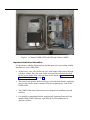
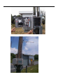
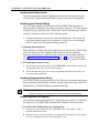
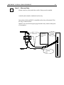
CORD-COM™
User’s Manual
Rohrback Cosasco Systems
11841 E. Smith Ave
Santa Fe Springs, CA 90670
Tel: (562) 949-0123
Fax: (562) 949-3065
P/N 720300-Manual Rev –
January 2002
Rohrback Cosasco Systems Inc. undertakes no obligation to update this manual or
to provide notice of any changes hereto. This manual is not intended to
constitute, modify, or enhance any warranty applicable to the product.
This manual is intended solely for the use by the purchaser of this product
for its intended purpose. This manual may not be used by other persons or
for other purposes without the express written consent of Rohrback Cosasco Systems.
Some or all of the information contained in this material may be copyrighted, or
contain specifications, drawings, processes, or other information subject to
patents or other intellectual property rights. Unauthorized use of such
information or materials may be in violation of applicable intellectual
property or other laws.
© 2001, 2002 Rohrback Cosasco Systems.
All rights reserved.
i
TABLE OF CONTENTS
Chapter 1 - Introduction........................................ 1
The CORD-COM Remote Monitoring Unit..................... 1
CORD-COM Features.................................................... 1
Input Channel Monitoring .................................................. 1
Input Channel Data Recording ........................................... 1
Programmable Periodic Call-Back Operation ..................... 1
Programmable Alarms....................................................... 1
Surge-Suppression Protection ...........................................2
Rectifier-Off Readings .......................................................2
GPS Synchronized Rectifier Interruption (Optional)............2
Communications Options...................................................2
Modem (Landline)............................................................................ 2
Cellular Telephone (AMPS).............................................................. 2
Cellular Telephone (GSM)................................................................ 2
Using This Manual ....................................................... 3
Corrpower Technical Support ...................................... 3
Chapter 2 - Setting Up Your CORD-COM............... 5
Hardware Installation .................................................. 5
CORD-COM Installation .....................................................5
Product Description......................................................................... 5
Important Installation Information ................................................... 6
Required Material............................................................................ 7
Installing the Enclosure ................................................................... 7
Installing the Safety Ground ............................................................ 9
Installing Input Channel Wiring........................................................ 9
Installing Communications Wiring ................................................... 9
Modem/Telephone Line Hook-Up ...................................................................9
Direct Connections via RS-232 port.............................................................10
Cellular Telephone Communications (AMPS and GSM) ............................10
Installing the CORD-COM Power Supply.........................................11
Commissioning Your CORD-COM..................................... 12
Verification of System Wiring and Rectifier Operation....................12
Verification of CORD-COM Operation............................... 13
Verifying Telephone Communications ............................................13
Performing Verification Readings in Direct-Connection..................14
Chapter 3 – CORD-COM Theory of Operation ......15
CORD-COM CPU Card ................................................15
Power/Bus Connections.................................................. 15
Communication/Antenna Connections............................. 16
Status Lights .................................................................. 16
CORD-COM ANALOG CARD ........................................18
Default Settings .........................................................19
Using CRM Software ..................................................19
Running the CRM Software Package ................................ 19
Connecting to the CORD-COM ......................................... 19
Connection by Modem and Direct Connections...............................19
General Connection Information.....................................................20
Chapter 4 - Troubleshooting................................21
Communications ........................................................21
‘No Answer from Modem’ Message Displayed ................. 21
‘Error in Modem Configuration’ Message Displayed ......... 21
‘Communications Error Between the PC Modem and the CORDCOM Modem’ Message Displayed.................................... 22
Problems With Erroneous Readings................................. 23
Appendix A - Site Report Form............................25
Appendix B - Computer Modem Configuration ....27
Appendix C - Technical specifications.................29
TABLE OF CONTENTS
Enclosure................................................................... 29
Power Supply............................................................. 29
CPU Board ................................................................. 30
Memory ......................................................................................... 30
Communications ............................................................................ 30
System Status................................................................................ 30
Analog Board ............................................................. 30
8 Differential Analog Inputs........................................................... 30
Input Ranges ................................................................................. 30
Precision ....................................................................................... 31
Channel Isolation........................................................................... 31
Input Impedance............................................................................ 31
Relay Output.................................................................................. 31
Status ............................................................................................ 31
Communication Options............................................. 31
Modem Option ............................................................................... 31
Cellular Telephone Option ............................................................. 31
Direct-Connect Serial Port............................................................. 31
Environmental............................................................ 31
CORD-COM Functions ................................................ 32
Appendix D – 8 Channel wiring Harness ............. 33
Appendix E – LIghtning Protection Box Wiring .... 35
APPENDIX F - INSTALLATION CHECKLIST......... 39
Installation block diagram ......................................... 39
Installation instructions ............................................. 40
Mount CORD-COM and Lightning Protection Unit ............. 40
Item 1 - GPS Antenna mounted on PVC enclosure ............ 40
Items 2and 3 - Antenna pole and cell phone antenna........ 41
Item 4 -Flex conduit and AC power to the CORD-COM ...... 42
iii
Item 5 – Connect CORD-COM to Lightning Protection Box 42
Item 6 – Lightning Protection Ground .............................. 42
Item 7 - Connect Lightning Protection Box to Rectifier .... 42
Item 8 - Mercury Relay................................................... 43
Commissioning the CORD-COM .................................44
Material required............................................................ 44
Initial verification ........................................................... 44
CHAPTER 1 - INTRODUCTION
1
CHAPTER 1 - INTRODUCTION
The CORD-COM Remote Monitoring Unit
Congratulations on your purchase of the CORD-COM Remote Monitoring
System. The CORD-COM is a state-of-the-art remote monitoring system
specially developed for the monitoring of corrosion control systems. Each
unit has been thoroughly tested before shipping and carries a 1 year
limited warranty.
The CORD-COM is a modular expandable remote monitoring system that
is used in conjunction with CRM remote monitoring software to
effectively monitor the operation of your corrosion control systems.
CORD-COM Features
Input Channel Monitoring
The standard CORD-COM unit comes with a single 8-channel analog card.
CORD-COM systems can be expanded to a maximum of 128 electrically
isolated input channels, by adding additional analog cards (providing the
enclosure has space for additional cards.)
Input Channel Data Recording
The CORD-COM can be programmed to record input information on any
or all installed input channels according to a schedule defined by the user.
The data collected can later be downloaded to a remote computer or
automatically collected as part of the Auto-Reporting procedure.
Programmable Periodic Call-Back Operation
The CORD-COM can be programmed to call a remote computer at regular
intervals to provide readings, download recorded data, etc. This allows for
low-maintenance monitoring of your site.
Programmable Alarms
The CORD-COM can be programmed to monitor for alarm conditions such
as AC power failure/restore, anomalous or out of limit input values,
system failure, and interruption start/stop. When alarm conditions are
recognised the CORD-COM can generate a call to a remote computer to
report the alarm condition.
Surge-Suppression Protection
While the CORD-COM unit includes over-voltage and transient surge
protection circuitry designed to safeguard the CORD-COM against possible
damage due to thunderstorms and any other voltage surge coming from
the telephone line, it is strongly recommended that the CORRPOWER
Lightning Protection Unit be installed on all inputs. See Appendix E for
more information on the Lightning Protection Box.
Rectifier-Off Readings
The CORD-COM unit can be configured to take readings with the rectifier
turned OFF if an optional external relay is installed in the rectifier.
GPS Synchronized Rectifier Interruption (Optional)
With the optional GPS module installed, the interruption of multiple
rectifiers units can be synchronized to insure accurate instant-off readings
are taken.
Communications Options
The CORD-COM can be used with a variety of electronic communication
mediums that premit CORD-COM remote monitoring units to installed
throughout the world.
Modem (Landline)
CORD-COM units can be equipped with a standard landline telephone
modem for remote communications via the telephone system.
Cellular Telephone (AMPS)
A 3 watt analog (AMPS standard) cellular telephone and cellular modem
is available for data communication when installing CORD-COM in areas
when analog cellular coverage. The AMPS standard is typically only
available in North America.
Cellular Telephone (GSM)
A 600 milliwatt dual band GSM cellular transciever and modem is
available for data communication when installing CORD-COM in areas
with GSM cellular coverage. Two models of GSM modems are available.
The 900Mhz/1800Mhz dual band model is the international GSM standard
and works throughout the world with the exception of North America.
The 900/1900 Mhz model works in North America.
CHAPTER 1 - INTRODUCTION
3
Using This Manual
Text that appears on the screen, or that needs to be entered by the user will
appear in the Courier font as follows: Entered Text.
The term ‘office computer’ refers to any computer in remote
communication with the CORD-COM using the CORRPOWER CRM
software.
All information contained in this manual applies to all CORD-COM
models unless noted otherwise.
Corrpower Technical Support
This manual has been designed to provide you with the information
needed to correctly install, configure and operate your CORD-COM remote
monitoring system. Should you still require assistance after having
consulted the appropriate sections of the manual contact CORRPOWER
Technical Support:
CORRPOWER Technical Support
Rohrback Cosasco Systems
11841 East Smith Ave.
Santa Fe Springs, CA 90670
Phone: (562) 949-0123
Fax: (562) 949-3065
CHAPTER 2 - SETTING UP YOUR CORD-COM
5
CHAPTER 2 - SETTING UP YOUR CORD-COM
Hardware Installation
It is advised that you read this chapter carefully, taking particular note of the
diagrams, before you attempt to install your CORD-COM.
WARNING During initial installation, make sure that you complete the Site
Report Form (see Appendix A - Site Report Form on page 25) and
that you have test both sending and receiving telephone communications
before leaving the site.
CORD-COM Installation
Unless specifically mentioned the following installation procedure applies to all
versions of the CORD-COM. Appendix F contains a CORD-COM installation
checklist which summarizes the installation procedures described in this chapter.
Product Description
Each CORD-COM system consists of the the following major components:
1] Enclosure
2] Power Supply Transformer
3] AC power switch and fuse
4] Backup battery
5] CPU Card with two RS-232 communication ports
6] Analog Card(s)
7] Communication Equipment (Modem, or Modem/Cellular Transciever)
8] pre-wired connections
These components are shown in the picture of a standard 8-channel CORD-COM
below:
Figure 1: 8 Channel CORD-COM with GPS and Cellular (AMPS)
Important Installation Information
It is important to take the following into consideration before proceeding with the
installation of your CORD-COM:
•
All necessary wires will exit the unit via a cable bundle which passes through
a flexible conduit. The color-code for the wiring will be indicated on a chart
located on the inside of the enclosure door and is shown in Appendix D – 8
Channel Wiring Harness on page 33.
•
The main circuit-breaker on the rectifier as well as the main breaker supplying
power to the rectifier must be turned OFF before beginning any work on the
CORD-COM.
•
The CORD-COM units with enclosures are designed for installation outside
rectifiers.
•
It is strongly recommended that the supplemental Lightning Protection Unit
installed with CORD-COM unit, especially those units installed on on
pipeline recitifiers.
CHAPTER 2 - SETTING UP YOUR CORD-COM
7
Required Material
Before beginning the installation of the system make sure you have the following
items at hand:
•
A standard multimeter.
•
Electrical lugs needed to connect the wires (#18) to the rectifier terminals.
•
Fittings for conduit installed between the CORD-COM, Lightning Protection
Unit (if installed) and the rectifier.
•
Necessary hardware (screws, brackets, or fixtures) to mount the unit in its
designated location (wall or pole, for instance).
•
Extra screws, cable ties and wire connectors.
•
A telephone line installed on-site if using non-cellular telecommunications.
•
A standard telephone or cell phone to be used for verification/troubleshooting.
•
Laptop computer with CRM installed and serial cable to connect to CORDCOM unit. (Required for commissioning)
Installing the Enclosure
The CORD-COM and Lightning Protection Unit enclosures should first be
positioned to insure the flexible conduit can be routed to the rectifier and the
communicaton cabling (telephone line, cellular telephone antenna, and/or GPS
antenna) can be properly routed to the enclosure. Once the enclosure(s) have
been properly positioned, attach the enclosure to its mounting surface with 4
screws, one in each back corner of the enclosure. If the CORD-COM enclosure is
not mounted on flat surface, brackets should be used to attached to the mounting
surface (for example, rectifier pole) and the CORD-COM enclosure should be
attached to the mounting brackets.
Two examples are CORD-COM system installations are shown below.
CHAPTER 2 - SETTING UP YOUR CORD-COM
9
Installing the Safety Ground
The green ground wire from the lightning protection unit and the green ground
wire from the CORD-COM should both be connected directly to earth ground.
Installing Input Channel Wiring
Up to 128 input channels can be monitored by the CORD-COM, though most
typical pipeline installations will not use more than 8 channels. The input channel
wiring was factory installed in the CORD-COM. Before installing input channel
wiring it is important to take note of the following points:
•
All input channels are electrically isolated and differential. That means that
each input channel requires its own ground, i.e. both wires for each channel
must be connected to the parameter being monitored.
! Lightning Protection Unit
When installing a CORD-COM with Lightning protection unit, the CORD-COM
cables are connected to the Lightning Protection Unit, then the Lightning
Protection Unit cables are connected to the rectifier or system being monitored.
(See Appendix E – Lightning Protection Box (page 35) for typical wiring when
using the CORD-COM/Lightning Protection Unit to monitor a pipeline rectifier).
! To install input channel wiring
1
Use the chart located on the inside of the CORD-COM enclosure door to identify the
input channel wires at the end of the cable bundle.
2
Attach the other end of the wires to the corresponding terminals at the rectifier site
(or system being monitored).
Installing Communications Wiring
Your CORD-COM has supplied with one of the following communication options:
direct connection with a portable computer, modem connection using a dedicated
telephone line, or cellular telephone communications link.
NOTE The CORD-COM has a second RS-232 serial interface to allow you to
connect a laptop to use during unit verification and troubleshooting.
Modem/Telephone Line Hook-Up
The telephone modem and telephone line surge protection module are installed on
the inside cover of CORD-COM’s configured for telephone modem operation.
! To connect the CORD-COM to the telephone line
1
Run the two wire telephone line into the CORD-COM. The telephone cable is
typically installed in conduit.
2
Remove the cover from the telephone line surge protection module by depressing the
tab with a flat blade screwdriver and removing the cover.
3
Connect the telephone wires to the terminals marked Line (E1a and E1b).se the
wiring identification chart located on the inside of the CORD-COM enclosure door
to identify the necessary telephone line wires at the end of the cable bundle.
NOTE The installation of the telephone line at rectifier site must be carried out by
qualified telephone service personnel and should be activated before
servicing.
The CORD-COM has been factory-configured to answer incoming calls after 2
rings. To modify the number of rings a CORD-COM waits before answering the
call, refer to section Specifying RMU Communications Parameters in the
CRM Software User's Manual.
Direct Connections via RS-232 port
The CORD-COM comes equipped with an RS-232 DB-9 port which allows you to
connect the unit directly to a computer.
The RS-232 port has a DB-9 female connector on all models. To connect your
computer to the CORD-COM you will need a standard serial cable with a DB-9
male and a DB-9 female connector. Connect the DB-9 male connector to the
CORD-COM port and the DB-9 female connector to the desired serial port on your
computer or radio.
NOTE Some computers use DB-25 connectors for their serial ports. In these cases
you will have to use an adaptor to connect the DB-9 cable to the DB-25
port.
Cellular Telephone Communications (AMPS and GSM)
The installation of the antenna and wiring used for units equipped with the
optional cellular telephone is described below.
! To install the cellular telephone antenna (no GPS antenna)
1
Mount the cellular telephone antenna in the desired location following the
instructions provided with the antenna.
2
CORD-COM units shipped from the factory with cellular telephones come with a
hole pre-dilled in the bottom of the CORD-COM enclosure which will allow the
antenna cable conduit to be fastened.
3
Fasten and seal the conduit to prevent water and fumes from entering the enclosure.
4
Pass the antenna cable through the conduit into the enclosure.
5
Locate the Mini UHF jack on the cellular telephone and screw the antenna cable into
the jack.
! Installing Cellular antenna with GPS antenna
1
For CORD-COM units with cellular communications and GPS interruption install the
GPS and cellular telephone antenna on the same mast.
CHAPTER 2 - SETTING UP YOUR CORD-COM
11
2
Run the cellular antenna cable through the water tigher fitting in the GPS antenna
housing and down the conduit/mast with
the GPS antenna cable as shown.
3
Attach the GPS antenna enclosure top to
the base by tightening the four screws
(one at each corner).
4
Attache the cellular antenna to the mast
using the instructions with the antenna.
5
Mount the mast with GPS and cellular
antennas.
6
After the cellular and GPS antenna
cables have been routed into the CORDCOM enclosure, locate the antenna jack
on the cellular transciever and screw the
antenna cable onto the jack. Screw the GPS antenna cable on the GPS antenna
adapter cable. Plug the other end of the GPS antenna adapter cable on the CPU card
GPS antenna connector.
Installing the CORD-COM Power Supply
WARNING 1 The CORD-COM’s ON/OFF switch only controls AC power to the
unit. The CORD-COM is always energized when the battery is connected.
It is very important to double-check all connections using a multimeter
before turning the switch to ON. To completely turn the CORD-COM off,
the ON/OFF must be in the OFF position and the power connector should
removed from the CPU card.
WARNING 2 The CORD-COM can be supplied with for use with either 120
VAC or 240 VAC. Make sure the CORD-COM is configured for the
proper AC power voltage being supplied..
NOTE When considering AC power connection possibilities for the CORD-COM
it is important to note that the unit should remain ON even when the
rectifier is turned OFF at the rectifier power switch.
! To install AC wiring
1
Use the wiring identification chart located on the inside of the CORD-COM
enclosure door to identify the necessary AC wires at the end of the cable bundle.
2
When used with a lightning protection box, the AC power wires typically go from the
CORD-COM to the Lightning Protection Unit and then to the AC power source.
3
Using wire-connectors or lugs connect the 115 VAC wire from the CORD-COM to
the 115 VAC terminal of the AC mains power and the LIVE wire from the CORDCOM to the LIVE terminal of the AC mains power.
4
Use a multimeter to double-check your connections.
5
Once the connections have been checked you can turn the AC ON/OFF switch to
ON. Using your multimeter, verify that 120 VAC is being supplied to the CORDCOM transformer.
6
Turn the AC ON/OFF switch to the OFF position.
7
The CORD-COM is shipped with the 8-pin CPU card power connector
(AC/BATT/CELL PWR/KW-h METER) disconnected. Plug the connector into the
CPU card and turn the AC ON/OFF switch to the ON position. After a few seconds,
the green POWER LED on the CPU card start flashing.
Commissioning Your CORD-COM
Once you have completed the installation of your CORD-COM unit you should
test your setup using the procedures described in this section.
Verification of System Wiring and Rectifier Operation
This procedure serves to make sure the CORD-COM is properly connected and
performing the proper readings.
To carry out the verification you will need a standard multimeter and a copy of
the Appendix A - Site Report Form which you will find on page 25.
! To perform a verification of system wiring and rectifier operation
1
Turn off the unit by turning the ON/OFF swithc to the OFF position and by removing
the power connector from the CPU card.
2
Turn rectifier ON.
3
Measure the channel voltages at the rectifier for each channel used by:
4
5
•
Read each channel by connecting the multimeter positive (+, or volt lead)
and negative (-) leads to the corresponding terminals on the rectifier
•
Enter these values in the Voltage @ Rectifier column of the Site Report
Form.
Measure channel voltages at the CORD-COM input channel terminal block for each
channel used by doing the following:
•
Read each channel by connecting the multimeter positive (+) and negative
(-) leads to the corresponding terminals on the Analog board terminal
block.
•
Enter these values in the Voltage @ CORD-COM Motherboard column of
the Site Report Form.
Compare the Voltage @ Rectifier values with the Voltage @ CORD-COM
Motherboard values to make sure there are no zero values or significant differences
in readings. A zero reading is indicative of a potential short circuit and should be
investigated.
CHAPTER 2 - SETTING UP YOUR CORD-COM
6
13
Once you are finished don’t forget to replug the power connector into the CPU card
and turn the CORD-COM ON/OFF switch ON.
Verification of CORD-COM Operation
Once you have finished the installation of your CORD-COM unit you must
perform a verification of its operation to make sure that everything is functioning
properly. There are two important aspects which must be verified at this point,
communication response, and the ability of the CORD-COM to perform readings.
Both of these can be verified at the same time by having someone use a computer
to call from a remote site using CRM Software. This verification procedure is
described below in the section Verifying Telephone Communications
beginning on page 13.
Additionally, if you have a portable computer with CRM at your disposal, you
can perform channel readings directly by using the RS-232 port on the CORDCOM. This optional procedure is described below in the section Performing
Verification Readings in Direct-Connection starting on page 14.
Verifying Telephone Communications
This verification procedure will require that you have someone make an AutoReporting call to the CORD-COM from a remote computer (off-site). This
procedure also assumes that the CRM Software has been installed in your office
computer and configured to call your CORD-COM unit. For information on how to
install and configure this software, refer to the sections Installing CRM
Software and Configuring CRM Communications in the CRM Software
User’s Manual that came with the software.
! To verify communications
1
Have your assistant perform an Auto-Reporting call to the CORD-COM using a
remote computer properly configured with the CRM Software (refer to Using
Auto-Reporting in the CRM Software User’s Manual).
2
Note the activity of the Status Indicator LED’s on the modem. The following should
take place in sequence:
a] The Status LED should blink the same number of rings the CORD-COM
has been programmed to wait before answering (2 rings by default);
b] The ‘screeching’ sound of the modem performing the handshake with the
other remote modem will be heard;
c] The Carrier Detect (CD) LED will then be lit, indicating that a connection
has been successfully established;
d] The Receive Data (RX) and Send Data (TX) LED’s will flicker,
indicating that data is being sent. After at least one minute (the duration
depends on the amount of data being collected) all of the LED’s except for
DTR will go out, indicating that the connection has been terminated.
3
Once communication between the office and RMU has been established, the
office will need to use CRM and verify that all analog channels are properly
configured.
4
Once the communication is finished, call your office to obtain the CORD-COM
readings and enter these in the Voltage via CORD-COM column of the Site Report
Form. Compare these values with those in the other two columns. Don’t forget to
take into account the multiplication factor and the offset used when configuring the
Site File. These should have been already entered on the Site Report Form in the
Channel Identification table. For more information refer to the section Verification
of System Wiring and Rectifier Operation on page 12.
NOTE If it is impossible for you to have someone call the CORD-COM using a
computer properly configured with the CRM Software, call Corrpower
Technical Support for assistance.
Performing Verification Readings in Direct-Connection
This procedure will allow you to obtain the same CORD-COM channel readings as
you would obtain using the Auto-Reporting procedure described above in the
section Verifying Telephone Communications on page 13. To carry out the
following procedure you will need the following:
•
a battery-operated portable computer equipped with an RS-232 connector and
running CRM.
•
a standard RS-232/DB-9 cable.
! To perform verification readings in direct-connection
1
Using the RS-232/DB-9 cable connect your portable computer to the RS-232 port on
the CORD-COM.
2
Run CRM making sure communications in direct connect and communications setup
uses 19,200 baud rate.
Select the site which has previously been setup. Click on the Remote Access
button in the Site Status window.
4 When the remote access screen is up, press connect, then select table view. In
table view, CRM will interrogate the CORD-COM and read the range each
analog channel is set at. Verify that the correct ranges are set. Use CRM lowlevel to properly set the channel ranges if required.
The general verification procedure is now complete.
3
CHAPTER 3 – CORD-COM THEORY OF OPERATION
15
Chapter 3 – CORD-COM THEORY OF OPERATION
CORD-COM CPU Card
The CORD-COM CPU card face plate is show in Figure x.
The connections to the CPU card are divided into three groups: the
power/bus connections, the communications/antenna connections and the
status lights.
Power/Bus Connections
At the top of the CPU card is an 8-pin and a 4-pin plug-in connector for
providing power and internal CORD-COM system communications.
These connectors are divided into the following sections:
•
AC – AC power is supplied to the CPU card. The power is in the
range of 12 – 24 volts VAC and is supplied from the step-down
transformer on backpanel.
•
BATT – The battery connected to these terminals. The CPU card
manages the charging of the sealed lead acid battery typically
supplied with the CORD-COM. The battery serves two purposes.
First, it supplies backup power in the event that AC power is lost,
enabling the CORD-COM to transmit AC power failure alarms.
Second, the battery supplies additional peak power to the system.
This peak power is typically used only when the cellular telephone
is transmitting.
•
CELL POWER – These terminals provide +12VDC regulated and
switched power to the cellular telephone or other communication
device connected to the CORD-COM.
•
KWH METER – These inputs are reserved for future use. When
implemented, CORD-COM will be able to reading a watt-hour
meter installed at the rectifier site.
•
CAN BUS – These four pins interface the CPU cards with the
Analog cards installed in the CORD-COM unit. The first two pins,
labeled PWR, provide regulated power to the analog cards. The
second two pins, labeled DATA, are a serial bus used to send
commands to individual analog cards and receive data from the
analog cards. All analog cards in a CORD-COM unit are
connected via daisy-chained connectors on the CAN BUS to the
CPU card.
Communication/Antenna Connections
Two 9-pin RS-232 connectors are found on the CPU card. The first
connector, labeled MODEM or COM2 is connected to the
communications device installed in the CORD-COM. Typical
communications devices used into land-line telephone modem or cellular
modem, either AMPS (analog) or GSM.
The second connector, labeled LAPTOP or COM1 is used communicate
with a local laptop computer directly connected to the CORD-COM. This
direct connection is typically used during installation and commissioning
or during troubleshooting.
CORD-COM units with the GPS option installed with also have an
antenna connector label GPS ANTENNA.
Status Lights
There are six status lights on a CORD-COM CPU card.
•
FAULT (Red)– The fault LED is off during normal operaton. When
on, the Fault LED indicates the CPU has detected a problem in
operation.
•
GPS 1PPS (Yellow) – In normal operation, when the GPS system is
locked on a satellite, this LED flashes once per second. This LED is
Off when there is no AC power, if the GPS module is defective, or if
GPS Satellite lock condition has been lost for long period.
•
POWER (Green) – The POWER LED gives the status of the power
supply. The POWER LED has the following options
•
LED Status
Description
1 Short Flash every
four seconds
No AC Power, CORD-COM is using only battery
power
1 Short Flash every
two seconds
AC POWER, Battery is fully charged. Normal
operation.
2 Short Flashes
every two seconds
The battery is being trickle charged. AC Power
present.
3 Short Flashes
The battery is in the fast charge mode. AC Power
present.
Continuous Flashes
During power-up, the LED will flash continuously for
approximately 2 seconds.
ALARM (Red) – The ALARM LED is on when the CORD-COM has
detected an enabled alarm condition. If Alarm Callback is enabled,
CHAPTER 3 – CORD-COM THEORY OF OPERATION
17
the Alarm LED will be turned off once the alarm condition has
successfully be transmitted to CRM.
•
LOCK TO SAT (Yellow) – This LED is lit when the GPS is
successfully locked on to at least one GPS satellite.
•
GPS CYCLE (Green) – When no GPS interruption cycle is active,
this LED is on. When a GPS interruption cycle is active, this LED
turns on and off when the same period as the interruption cycle. These
signals are 0.5 seconds in advance of the actual interruption itself.
CORD-COM ANALOG CARD
The CORD-COM analog card face plate is shown in Figure x. The analog
card communicates with the CPU card in the CORD-COM system via a
four pin CAN-BUS connector. Two of the CAN-BUS pins provide power
to the analog card, but the other two pins are used to commuicate with the
CPU and other analog cards in the systems.
The analog card has 8 isolated differential input channels, grouped on two
sets of 4 channels (8 input pins each). The voltage range for each channel
is set under program control using CRM.
Each analog card also has a digital relay drive output which is typically
used to interrupt the rectifier output.
The POT pins on the analog card can be used to connect to
CORRPOWER’s CORD-POT electronic potentiometer. With the CORDPOT, the output of electronically controlled rectifiers can be remotely
adjusted.
The three status lights on the analog card are used to communicate system
status without having to connect a laptop to the CORD-COM unit. The
status LEDS are:
•
POWER (Green) – The Power LED is on when there is power
supplied to the analog card.
•
RELAY STATUS (Yellow) - This LED displays the status of the
relay drive output. When the Relay Status LED is lit, the relay drive is
off, when the Relay Status LED is Off, the relay drive is on. While
this may be confusing, in normal operation with a normally closed
relay installed on the rectifier output, when the Relay Status LED is lit,
the rectifier is ON, and when the Relay Status LED is off, the rectifier
is also OFF.
•
FAULT (Red) – The Fault LED is lit or on to identify system faults.
CHAPTER 3 – CORD-COM THEORY OF OPERATION
19
Default Settings
Certain CORD-COM and CRM Software settings have been assigned a
default value before shipping. Upon connecting to your CORD-COM for
the first time the following values are in effect:
•
No channels selected for data recording.
•
The internal clock is set to Pacific Standard Time.
•
The RMU Name field has not been assigned and is blank.
•
None of the Call-Backs are enabled.
•
The CORD-COM is configured to answer a call after 2 rings. In the
case of cellular units, the CORD-COM/CELL, these are configured to
answer after 2 rings.
Using CRM Software
Rohrback Cosasco Systems CRM Software allows you to perform CORD-COM
corrosion monitoring from a remote computer connected via modem to a standard or
cell phone line. In order to carry out your monitoring tasks you must first
run the software package and create a site file for each CORD-COM you
would like to monitor. Refer to Chapter 3 Using CRM in your CRM
Software User's Manual.
Running the CRM Software Package
All of the files necessary that are required to run the CRM Software have
been installed in the CRM directory at the root level of your hard drive
during the installation process.
Connecting to the CORD-COM
It is possible to establish a connection with the CORD-COM in 2 different
ways, either by modem or in direct connection.
Connection by Modem and Direct Connections
All CORD-COM units have a RS-232 communication port (COM1) and a
local or laptop RS-232 communication port (COM2). The connection
procedure for both direct and modem connections is identical except for
the Connection Setup in the Communications Menu (refer to the section
Specifying Site Communications Parameters in the CRM
Software User's Manual). Select the PC TabType to Modem for a
modem connection and Direct for a direct connection.
NOTE Call-Backs and Data Recording cannot take place when the CORDCOM is in a Direct Connection (i.e. non-modem) with the CORDCOM.
General Connection Information
Connection Timeout
The CORD-COM will automatically terminate a connection after a
period of inactivity lasting more than 5 minutes.
NOTE A bad cell phone connection may produce too much ‘garbage’ and
cause the CORD-COM unit to hang up.
CHAPTER 4 - TROUBLESHOOTING
21
CHAPTER 4 - TROUBLESHOOTING
Communications
If you are having trouble placing a call, have the CRM Log File displayed
for that site to view the possible error messages which would be generated
by your call attempts.
‘No Answer from Modem’ Message Displayed
If you see the following entry in the Log File:
02-14-1995 16:11:03 No Answer from Modem
Verify the following aspects of your communications setup: in the order
given:
•
Check to see that you are using the correct communications port (1 or
2) for your modem.
•
If you are using an external modem and the SEND DATA and
RECEIVE DATA LED’s are flashing when you call you may have an
improperly configured modem. Refer to ‘Error in Modem
Configuration’ Message Displayed on page 21 below. If the SEND
DATA and RECEIVE DATA LED’s do not flash double-check cable
connection between computer and modem. Also make sure that the
modem is plugged in and turned ON.
•
If you are using an internal modem make sure it is recognized by your
computer’s software and that it is turned ON using the configuration
software provided for this purpose by the computer’s manufacturer.
‘Error in Modem Configuration’ Message Displayed
If you see the following entry in the Log File:
02-14-1995 16:11:03 Error in Modem Configuration
Verify the following aspects of your communications setup: in the order
given:
•
Attempt to perform an Auto-Reporting Call and observe the
messages which appear in the Received window. Except for the
initial ATZ command, all commands will be acknowledged by an OK.
If an OK acknowledgment fails to appear after the AT&Q0 command,
or if the message Error appears, disable ‘intelligent’ error-correction
by setting proper modem init string in site setup of CRM. If an OK
acknowledgment fails to appear after any other command, or if the
message Error appears, note this command and call Corrpower
Customer Support.
‘Communications Error Between the PC Modem and the CORD-COM
Modem’ Message Displayed
If you see the following entry in the Log File:
02-14-1995 16:11:03 Communications Error Between the PC Modem and the CORD-3 Modem
This is an indication that the CORD-COM is not answering the call.
Verify the following aspects of your communications setup in the order
given:
•
Call the site using a standard telephone. If there is no answer, contact
the phone company to find out whether there have been any telephone
line problems in the area where the CORD-COM is installed.
•
Have someone go on-site with a telephone, a spare telephone cord,
slow-blow 3 Amp. fuses (MDL3) for the surge suppressor (CORD3/WT and CORD-COM only), or extra telephone line surge suppressor
(CORD-3 standard version), and a multimeter.
1] When on-site check to see if the 1200 baud and Ready LED’s are
ON. If they are not ON check CORD-3 power connections using
the Troubleshooting: Power Connection Verification procedure
described below. If the LED’s are ON, plug the telephone into the
RJ-11 jack and check to see if there is a dial tone. If you do not get
a dial tone, check the connection between the RJ-11 jack and the
telephone network. If it seems to be in order call your telephone
company to have them check the line. If you get a dial tone, call
the office and have them perform a Auto-Reporting Call. Don’t
forget to hang up and disconnect the laptop computer from the unit
to allow the Auto-Reporting Call to come through. Watch the
modem LED’s; if the Auto Answer LED flashes when the phone
rings, this means the telephone connection is functioning properly.
If the Auto Answer LED does not flash:
[•TBD]
CHAPTER 4 - TROUBLESHOOTING
23
Problems With Erroneous Readings
If you have been obtaining readings during Auto-Reporting or Call-Back
that you feel are inaccurate or not what you expected use the following
procedure to determine possible causes.
•
Establish a Remote Access-Low Level connection between the RMU
and CRM. Use the low-level command 0047, to obtain a ‘manual
readings’ Compare the readings thus obtained with those obtained by
the CORD-COM and displayed in CRM. If the readings are different,
check the multiplication factors entered in the Site Setup/Channels
screen in CRM, adjust to the desired values and perform another AutoReporting call. If the readings match go to next step.
•
If the readings are off by a factor of 10, 100, 1000, etc. from what you
expected, check the channel ranges by using command 0048 (while
still in Remote Access LowLevel) Compare these values with those
entered on the Site Report Form.
If you still have problems with erroneous readings you will either have to
go on-site with a battery-operated portable computer, or, if you don’t have
a portable computer, you will have to go on-site and have someone at the
office who knows how to use CRM Software assist you by calling the
CORD-COM at the remote site. The person going on-site will also need a
multimeter.
!
WARNING If you do use a portable computer on-site make sure to use it
only using the battery; plugging the computer into an AC socket on site
could result in a ground loop which could lead to erroneous readings.
Once you are on-site try the following:
1] Once you are on-site connect your computer to the CORD-COM using
the RS-232 port (see section Connection by Modem and Direct
Connections on page 19) and perform channel readings. Using the
multimeter perform manual readings of the same channels directly on
the terminal block of the CORD-COM. Compare the two sets of
readings, taking the following channel range multiplication factors into
account:
2] If the above verification failed to solve your problem verify the ground
and common connections to the motherboard and at the rectifier,
making sure they are not damaged, loose, etc... If they appear properly
connected, short the ground and the common by connecting them (with
a jumper for example) and perform readings with the CORD-COM. If
this solves the problem it may mean that rectifier noise is interfering
with the common (negative) connection. Call Corrpower Technical
Support for assistance on how to proceed.
APPENDIX A - SITE REPORT FORM
25
APPENDIX A - SITE REPORT FORM
CRM Software
Date:_____________________________________Prepared by: _________________________
Site Name: ________________________________Rectifier Manufacturer: _________________
Site Number: ______________________________Model: ______________________________
Company: _________________________________Serial #: ____________________________
Address: ______________________________________________________________________
Rectifier Information and Firmware Revision
Capacity: ___________Volts __________________ Amperes __________________________
Site Description: ________________________________________________________________
Channel Identification
CHANNEL #
Input
Range
MULTIPLIER AND
OFFSET
DESCRIPTION
1
2
3
4
5
6
7
8
ADDITIONAL REMARKS:________________________________________
_______________________________________________________
Installation Verification
Channel #
Manual Readings with Voltmeter
Voltage @ Rectifier
1
2
3
4
5
6
7
8
Voltage @ CORD-COM Analog
Card
Readings Performed by CORD-COM
Voltage via CORD-COM
APPENDIX B - COMPUTER MODEM CONFIGURATION
27
APPENDIX B - COMPUTER MODEM
CONFIGURATION
The modem used at the computer end of the connection with the CORDCOM should have the same technical specifications as the modem
connected to the CORD-COM, which are:
Baud Rate
4800 baud cellular
19200 baud land-line
Data Bits
8
Stop Bit
1
Parity
None
Duplex
Half
Before using the instructions below to configure the modem in your
computer, contact Corrpower Technical Support.
! To configure the modem connected to your computer
1
Connect the modem to your portable computer.
2
Run your communications program (most standard communications software
can be used). Check that you are in echo mode.
3
Set the Communication parameters to the following: RATE: 1200 baud;
DATA BITS: 8; STOP BITS: 1; PARITY: none, DUPLEX: half.
4
Enter the following commands; the modem should respond with OK after
each command is sent (Be sure to press [ENTER] after each entry):
AT&F0
Loads default factory profile for Hayes Modems.
AT&W1
Permanently stores this setup as profile 1.
ATS0=4
Sets modem to answer calls after 2 rings.
ATS7=255
Sets modem to wait a maximum of 255 seconds for the
computer to answer when it is dialing out.
ATS9=20
Sets carrier detection time to 2 seconds.
ATS10=50
Sets delay between lost carrier and hangup time to 5
seconds.
ATS11=120 Sets DTMF dialing speed.
ATS30=60
Sets inactivity time-out to 600 seconds. Modem hangs
up if no activity detected during 600 seconds.
ATS108=2
Sets signal quality selector to 2 (medium).
ATE0
Sets modem to no echo.
ATV1
Result codes in alphanumeric format.
AT&C1
Data Carrier Detect (DCD) tracks the state of the DCD
from the remote modem.
AT&D0
Data Terminal Ready (DTR) from the CORD-4 is
ignored.
AT&R1
Ignore RTS and asserts CTS when the modem is on
line.
AT&Q0
Turns off error-correction.
AT&Y0
Selects stored profile 0 on power up.
AT&W0
Store this setup permanently as profile 0.
5 Turn the Modem OFF. Turn it back ON. Enter the command AT&V. The
modem should display something similar to the following on your screen:
ACTIVE PROFILE:
DTE:1200
DCE:1200
PARITY:NONE
B16 B1 E0 L2 M1 N1 P Q0 V1 W0 X4 Y0 &A0 &B1 &C1 &D0 &G0 &J0 &K3 &L0 &Q0
&T4 &U0 &X0 &Y0
S00:004 S01:000 S02:043 S03:013 S04:010 S05:008 S06:002 S07:255 S08:002
S10:050 S11:120 S12:050 S18:000 S25:005 S26:001 S30:060 S36:007 S37:000
S43:000 S46:002 S48:007 S49:064 S50:220 S63:009 S82:128 S86:000 S95:000
S108:002 S109:062 S110:002 S136:001
STORED PROFILE 0:
B16 B1 E0 L2 M1 N1 P Q0 V1 W0 X4 Y0 &A0 &C1 &D0 &G0 &J0 &K3 &L0 &Q5 &R1
S00:004 S02:043 S06:002 S07:090 S08:002 S09:020 S10:050 S11:120 S12:050
S25:005 S26:001 S30:060 S36:007 S37:000 S38:020 S46:002 S48:007 S63:009
S95:000 S97:030 S108:2 S109:062 S110:2 S136:001
STORED PROFILE 1:
B16 B1 E1 L2 M1 N1 P Q0 V1 W0 X4 Y0 &A0 &C0 &D0 &G0 &J0 &K3 &L0 &Q5 &R0
S00:000 S02:043 S06:002 S07:050 S08:002 S09:006 S10:014 S11:095 S12:050
S25:005 S26:001 S30:000 S36:007 S37:000 S38:020 S46:002 S48:007 S63:009
S95:000 S97:030 S108:1 S109:062 S110:2 S136:001
TELEPHONE NUMBERS:
&Z0=
&Z1=
&Z2=
&Z3=
&R1 &S0
S09:020
S38:020
S97:030
&S0 &T4
S18:000
S82:128
&S0 &T4
S18:000
S82:128
OK
6
Double-check that only differences between profile 0 and profile 1 consist of
those made changes made above.
7
Verify that profile 0 was restored as the active profile.
8
You are ready to set up your modem to call up the CORD-COM to establish
remote communications.
APPENDIX D – 8 CHANNEL WIRING HARNESS
29
APPENDIX C - TECHNICAL SPECIFICATIONS
Enclosure
Model
Material
Dimensions
CORD-COM
(8 channel)
NEMA-4X, Fiberglass
29.2 x 22.9 x 16.5 cm
(11.5” x 9” x 6.5”)
CORD-COM
(24 channel)
NEMA-4X, Fiberglass
Power Supply
Input Voltage:
120 VAC
Input Current:
40 milliamperes when idle; 120 milliamperes while in
communication.
Optional Power
Source:
24 VDC
CPU Board
Memory
128 K of RAM is standard on the CPU board. There is approximately
100K availabe for data storage, which is sufficient for storing 50,000
individual channel readings.
Communications
Two RS-232 communication power. COM1 is used to connect a laptop
computer for on-site commissioning, troubleshooting and access to the
RMU. COM2 connects to the communication system modem used by the
CORD-COM.
System Status
The CPU card has six system status lights: Fault (Red), GPS 1 PPS
(Yellow), Power (Green), Alarm (Red), Lock to Satellite (Yellow), GPS
Cycle (Green)
Analog Board
8 Differential Analog Inputs
Each analog card has 8 differential analog inputs per card.
Input Ranges
Each input channel has the following ranges, which are selectable under
program control:
+ 100 mv DC
+ 10 V DC
+ 100 V DC
+ 350 V DC
APPENDIX D – 8 CHANNEL WIRING HARNESS
31
Precision
+ 0.5% on DC readings
+ 1% of AC readings
Channel Isolation
1000 V isolation between each channel. Each analog channel will handle
a common mode voltage of up to 400 volts.
Input Impedance
22 Megohm for the 10, 100 and 350 Volt ranges
230 Kohm for the 100 mv range
Relay Output
Each CORD-COM Analog card has one digital relay drive output.
Status
Each analog card has three status lights: Alarm (Red), Relay Status
(Yellow), Power (Green)
Communication Options
Modem Option
One RS-232C serial port reserved for Modem communications. A xxxx
baud modem is provided with the modem option.
Cellular Telephone Option
3 – watt analog cellular transciever (AMPS standard) and cellular modem
are available for North American areas with analog cell coverage.
GSM cellular transciever and modem are available. A dual band GSM
transciever (900/1800 Mhz) is supplied for non-US locations with GSM
cellular coverage and a 1900 Mhz GSM transciever can be provided for
United States based GSM systems.
Direct-Connect Serial Port
One RS-232C serial port (DB-9) for Direct-Connection of (portable)
computer.
Environmental
•
Operating Temperature: -40 to 70° C (-40 to 158 ° F).
•
Humidity: 80% relative humidity, non-condensing.
CORD-COM Functions
•
Auto-Reporting.
•
Programmable Call-Back Operation using up to 5 different telephone
numbers.
•
User-programmable Data Recording with sampling rates ranging from
once per second to once per month.
APPENDIX D – 8 CHANNEL WIRING HARNESS
33
APPENDIX D – 8 CHANNEL WIRING HARNESS
The 8-Channel CORD-COM comes with all external connections prewired in a cable harness inside a four foot long flexible conduit. The
wires in the cable harness are coded as follows:
Color Code
Green
Wire
Gauge
14
Function
Ground
Black
14
110 V AC (hot)
White
14
110 V AC (neutral)
Orange
18
Relay Drive +
Blue
18
Relay Drive -
White on Green
22
Channel 1 +
White on Blue
22
Channel 1 -
Red on White
22
Channel 2 +
Red on Black
22
Channel 2 -
Red on Orange
22
Channel 3 +
Orange
22
Channel 3 -
Red on Blue
22
Channel 4 +
Black
22
Channel 4 -
Black on Red
22
Channel 5 +
Blue
22
Channel 5 -
Black on Green
22
Channel 6 +
Orange
22
Channel 6 -
Black on White
22
Channel 7 +
Black on Blue
22
Channel 7 -
White
22
Channel 8 +
White on Black
22
Channel 8 -
APPENDIX E – LIGHTNING PROTECTION BOX
35
APPENDIX E – LIGHTNING PROTECTION BOX
WIRING
The lightning protection unit should be connected between the CORDCOM unit’s analog input channels and the physical connections to the
rectifier or device being monitored. All wire connections from the
CORD-COM analog inputs on terminated on the screw terminals between
the wirewound resistors and the MOV (blue disk). The connections to the
rectifer or device being monitored are made using the pre-wired cable
bundle in the lighting protection unit.
The following block diagram shows a three channel Lightning Protection
Unit:
Resistor
MOV
Red
Resistor
MOV
Grey
Resistor
MOV
Yellow
Resistor
Brown
Resistor
Copper Bus Bar
Purple
MOV
Ground From
Cord-COM
Wire Bundle to
Rectifier
Ground
Wire
Wiring From CordCOM
The following tables provide two examples for connecting a three channel
Lighting Protection Box to a rectifier with reference cell. The first
example assumes the rectifier shunt is on the negative leg of the rectifier.
The second example assumes the shunt is on the postive leg. Both
examples use CORD-COM channel 1 for rectifier volts, channel 2 for
rectifier amps and channel 3 for reference cell or pipe-to-soil potential.
Rectifier with Shunt on Negative Leg
Lightning Box
Wire
Terminate at
Cord-Com Wire
Terminate in
Lightning Box
Purple
Rectifier Shunt (pipe
side)
White on Blue (Ch 1-)
Red on White (Ch 2+)
1 Resistor
(Top)
Red
Rectifier +
White on Green (Ch 1+)
2 Resistor
Grey
Rectifier Shunt
(rectifier side)
Red on Black (Ch 2-)
3 Resistor
Yellow
Reference Cell Wire
Orange (Ch 3-)
4 Resistor
Brown
Structure Wire
Red on Orange (Ch 3+)
5 Resistor
(Bottom)
st
nd
rd
th
th
Shunt on - Output
Rectifier
Lightning
Protection
Orange
Blue
F
To Diode
Bridge
+
Purple
-
+
-
White on Blue
White on Green
+1
Relay
Channel
Red
Red on White
-
+
Orange
Yellow
Brown
Red on Orange
Green
# 12 Green
Ref. Cell
Pipeline
+2
-
Red on Black
Gray
-
C
CORD-COM
-
+
+3
Channel
Channel
APPENDIX E – LIGHTNING PROTECTION BOX
37
Rectifier with Shunt on Positive Leg
Lightning Box
Wire
Terminate at
Cord-Com Wire
Terminate in
Lightning
Box
Purple
Rectifier -
White on Blue (Ch 1-)
1 Resistor
(Top)
Red
Rectifier +, Shunt
(anode side)
White on Green (Ch 1+)
Red on Black (Ch 2-)
2 Resistor
Grey
Rectifier Shunt
(Rectifier Side)
Red on White (Ch 2+)
3 Resistor
Yellow
Reference Cell Wire
Orange (Ch 3-)
4 Resistor
Brown
Structure Wire
Red on Orange (Ch 3+)
5 Resistor
(Bottom)
st
nd
rd
th
th
Shunt on + Output
Rectifier
Lightning
Protection
Orange
Blue
To Diode
Bridge
+
-
Purple
+
White on Blue
White on Green
Red
Red on Black
Gray
Red on White
Orange
+
Yellow
Brown
Red on Orange
Green
-
# 12 Green
Ref. Cell
Pipeline
+1
+2
-
F
-
C
CORD-COM
-
-
-
+
+3
Relay
Channel
Channel
Channel
APPENDIX F - INSTALLATION CHECKLIST
39
APPENDIX F - INSTALLATION CHECKLIST
This checklist is designed for the installation of an 8-channel CORD-COM
unit with GPS and Cellular telephone options and a Lightning Protection
Unit at a typical pipline cathodic protection rectifier.
Installation block diagram
1
2
CORD-COM
Surge
Protection
Rectifier 1
3
115 VAC main
supply breaker
box
4
5
Rectifier 1
6
8
7
Note 1: All conduits from bottom of enclosures. Side and top penetration
not allowed.
Note 2: All wire and cable must be sealed using electrical putty inside the
enclosures.
Installation instructions
Mount CORD-COM and Lightning Protection Unit
Select the location and method for securing the CORD-COM unit and the
Lightning Protection unit. Mount both unit with screws or bolts at the four
corners of each unit.
Item 1 - GPS Antenna mounted on PVC enclosure
The GPS Antenna was shipped mounted on a PVC junction box. It has a 1
inch female threaded fitting to screw the box directly on a 1 inch metallic
pole which support the antennas ( item 3). The GPS and the cellular
antenna cable must run inside the antenna pole and the flex conduit.
There is no work to do on the GPS antenna itself. Just screw the TNC end
of the antenna cable to the antenna and run the cable in the metallic pole
The junction box provides a weather sealed cable pass through for the
Cellular phone antenna cable. Unscrew the PVC cover from the adapter.
Run the Mini UHF end of the antenna cable through the cover just
unscrewed. Then run the cable through the antenna pole.
TNC to
GPS
antenna
Cut rubber
seal as shown
Mini UHF to cell
Phone
TNC to CORDCOM GPS
receiver
Type N to Yagi antenna,
UHF to cell Phone
APPENDIX F - INSTALLATION CHECKLIST
41
Items 2and 3 - Antenna pole and cell phone antenna
The Cellular phone antenna is a mounted to the antenna pole using the
supplied U clamp. Mount the cellular antenna cable 6 inches below the
bottom of the GPS antenna. The standard length for the antenna pole is 5
ft.
The N type connector (largest one) of the cellular phone antenna cable is
screwed to the antenna.
Use sealing tape to cover completely the connectors once screwed.
Once antenna is installed and oriented for optimum cellular phone
reception, screw the weather tight connector on the PVC box and secure
the antenna cable with tie wraps as shown.
The 2 cables should be cut to proper length inside the CORD-COM
enclosure.
Electrical Tape
Tie Wraps
U Clamp
Antenna pole 1
inch rigid pipe
5 ft long
Tie Wraps
1 inch fitting
Reducer 1 inch
to ¾ inch
Adapter for 3/4
inch flex conduit
3/4 inch
flexible conduit
Adapter for 3/4
inch flex conduit
Item 4 -Flex conduit and AC power to the CORD-COM
Install ½ or ¾ inch flexible or rigid conduit between the CORD-COM
enclosure and main AC supply breaker box.
Insure AC wiring is done as per electrical code. Plastic flex conduit may
not be accepted. Metallic flex conduit is normally accepted up to a
maximum length.
Connect the black and the white wire from the CORD-COM harness to the
power source as per Electrical code.
Terminate the # 12 green from the CORD-COM bottom plate to the the
copper buss bar in the lightning protection box.
Insure that all conduits terminating in the CORD-COM enclosure are
sealed with standard electrical putty.
Item 5 – Connect CORD-COM to Lightning Protection Box
Connect the flexible conduit from the CORD-COM unit to the lightning
protection enclosure by cuting the conduit to the correct length, taking
care not to cut any of the wires inside. Install the conduit termination and
in the Lightning box and connect the flexible conduit.
The orange and blue wires are used to drive the mercury relay inside the
rectifier. Those wires must go from the CORD-COM to the Lightning
protection box and continue to the Rectifier. The supplied harness may
not be long enough. Those wires are not connected to anything in the
Surge protection enclosure. They just pass through.
Item 6 – Lightning Protection Ground
Coonect the green ground wire from the Lightning Protection unit directly
to a ground rod. Using the rectifier chassis is not acceptable.
This is a very important connection as is insures the drainage to ground of
the surges from lightning. If those ground connections are not done
properly, the entire surge protection will not operate properly and the
CORD-COM will not be protected adequately.
Item 7 - Connect Lightning Protection Box to Rectifier
Connect the flexible conduit from the Lightning protection unit to the
rectifier.
Terminate the wires from the lightning protection unit in the rectifier as
per the wiring diagram. Insure that you identify if the shunt is on the + or
– output and use the proper wiring diagram.
APPENDIX F - INSTALLATION CHECKLIST
43
Item 8 - Mercury Relay
Mount a mercury relay inside the rectifier. Relay must be installed
vertically and oriented as indicated on the relay.
Insure that a diode and MOV is installed on the relay coil terminal. Wire
the relay as shown below.
Install 2 wires rated to the proper gage from the relay contact to the point
of interruption.
- Blue wire
Lightning
Protection
Unit
+ Orange
wire
Analog
Module
Commissioning the CORD-COM
Material required
1 Notebook computer running Windows 95 or newer running on
battery. Corrpower CRM software must be installed.
2
Serial interface cable DB9 Female to DB9 male.
3
Multimeter wit a 3 ¾ or 4 ½ digits resolution.
Initial verification
1 Insure that the main breaker is turned OFF.
2 Verify all wiring and correct errors.
3 Insure that the main CORD-COM power switch is in the OFF
position. (Press the lower portion of the switch)
4 Measure the DC voltage, DC current and the reference electrode
voltage at in the rectifier, in the Surge protection enclosure and on the
orange connector on the Analog module of the CORD-COM. Report
those readings on paper for your validation report.
5 Measure the AC voltage going to the RMU. It must be 105 to 130
Volts AC. Insure that this voltage is stable.
6 The CORD-COM was shipped with the AC, DC and cellular power
connector disconnected. Connect this connector. You may see LEDs
turning ON. This is normal. However, unless you apply the main AC
power, the system will not run. Press the main power switch on its
upper section to turn the CORD-COM ON.
7 Run the CRM software on your Notebook. Connect the serial cable to
the LAPTOP connector of the CORD-COM. Access Communication
Setup and set RMU Baud Rate for CORD-COM to 19200.
8 Select COMMUNICATION DIRECT from the Communication pull
down menu.
9 Insure you created one site to do the commissioning. That site must
be a CORD-COM using Cellular phone.
10 Double click on the ICON representing the test site to access the Site
Status and tools Window.
11 From Site Status and tools window, click on REMOTE ACCESS to
access the Site Remote Access Window.
12 From the Site Remote Access Window, click on connect to open the
serial port. The command list shall now be accessible.
13 You should use only the keyboard keys from now on. It should be
faster if you work outside. Use the Arrow keys to select a command.
Use the TAB key to change section. Press enter to execute…
14 Select command 0001. Then press select the PASTE button. Press
ENTER to paste the command in the command box. Press TAB to
APPENDIX F - INSTALLATION CHECKLIST
15
16
17
18
19
45
select the SEND button. Press ENTER to SENT the command to the
CORD-COM. You should practice this operation before to attempt to
write anything to the CORD-COM.
To validate the channels, use command 0047. Select one channel at a
time and instead of using the SEND button, use the LOOP. This will
keep reading the selected channel until you stop. You use that
function to verify that the reading on each channel is the same as the
ones you took with your multimeter. You must also insure that the
readings are stable.
You must validate all channels used.
You must ENABLE the GPS interruption cycle to validate that the
mercury relay is wired properly. This will be possible if the GPS
antenna is connected properly and if the LOCKED TO SAT LED is
ON.
Write down all readings taken with the CORD-COM. This is
necessary to generate the installation report.
Disconnect your computer form the CORD-COM. Use your cellular
phone to call the CORD-COM cellular phone number. Pay attention
to the CORD-COM modem answering the call and hear the high
frequency modem. This indicates you that the system should operate
properly when a computer calls it.