1
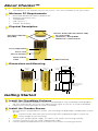
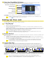
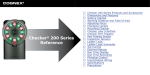
Quick Reference
About Checker™
•
•
Checker is the sensor.
CheckMate™ is the software that runs on your PC. You use CheckMate to set up Checker.
Minimum PC Requirements
•
Microsoft® Windows® 2000 or Windows XP
•
•
•
•
400MHz Pentium® III CPU
128 MB RAM
USB version 1.1
1024 by 768 Display
Physical Description
Checker Status Indicator (Green LED)
On = Run mode
1 Blink/sec = Setup Mode
4 Blinks/sec = Internal Error
Part Status Indicator
(Red LED)
Focus Adjustment
Focus Lock
M3 (1.5 mm hex)
Power and I/O
Cable
USB Connector
Dimensions and Mounting
45.9 mm
1.806”
53.2 mm
2.094”
39.4 mm
1.550”
19.8 mm
0.778”
19.5 mm
0.772”
60.3 mm
2.375”
129.2 mm
5.087”
111.6 mm
4.383”
3X mounting holes
M4x0.70 thread
0.32”deep
Getting Started
1 Install the CheckMate Software
1
2
Insert the CheckMate CD-ROM in your PC’s CD-ROM drive. The CheckMate install program
will start automatically. You must have Administrator rights on your PC to install CheckMate.
Follow the on-screen prompts to install CheckMate.
2 Install the Checker Sensor
1
Mount Checker using 3 M4x0.70 screws. The mounting should provide a suitable path to earth
ground.
!
2
3
4
Checker comes with three sets of mounting screws of different lengths; choose the
correct length for your mounting.
Connect your 24 VDC power supply, as shown in the section Connecting Checker.
Connect Checker to your PC using supplied USB cable.
Connect input and output devices, as shown in the section Connecting Checker.
3 Start the CheckMate Software
Start CheckMate by double-clicking on the CheckMate icon. (The first time that you start
CheckMate, it may take a moment before your PC recognizes Checker.)
Questions and Answers
Checker Status
Job Setup Steps
Controls
Filmstrip
Filmstrip Control
CheckMate always displays a list of questions and answers related to the current state of
CheckMate.
!
For detailed information on how Checker works and how to use CheckMate, click
on the
button to open the User’s Manual.
Setting Up Your Job
A Checker job contains all of the information that Checker needs to check your part. You set up a
Checker job in four simple steps using CheckMate.
1 1. Get Started
•
Create a new job.
•
•
Enter your line speed and direction.
Place a ruler at the same distance from Checker as your part will be, and enter the size of
Checker’s field of view.
If you specify a horizontal machine direction, this size is the distance between the left and right
edges of what Checker can see; if you specify a vertical machine direction, the size is the
distance between the top and bottom of what Checker can see.
Adjust the image brightness and focus Checker on your part.
•
!
Checker is shipped with its focus unlocked. If you have tightened the focus lock,
make sure to loosen it before adjusting the focus.
2 Detect My Part
Before Checker inspects your part, it must detect that your part is present. Checker can detect your
part in two ways:
1
2
Checker can detect parts using a Part Finding Sensor. Simply create a Part Finding Sensor
and place it over a part feature that Checker can always see.
You can use an external photoelectric sensor to tell Checker that the part is present. Checker
uses the rising edge of the input signal.
!
If you use both an external photoelectric sensor and a Part Finding Sensor, both
the photoelectric sensor and the Part Finding Sensor must indicate that the part
is present before Checker will inspect the part.
3 Inspect My Part
Create an Inspection Sensor for each part feature that you want to check. The result of an
Inspection Sensor can be pass or fail. The results of all Inspection Sensors must be pass for
Checker to pass your part. If the result of any Inspection Sensor is fail, Checker will fail your part.
Checker provides three types of Inspection Sensors: Brightness Sensors detect bright features;
Contrast Sensors detect high-contrast features; and Pattern Sensors detect matching patterns.
Brightness Sensor
Brighter
Contrast Sensor
More contrast
Pattern Sensor
No
match
Partial
match
Match
To create an Inspection Sensor, click on the feature to check, then adjust the Sensor’s threshold so
that good parts are above the threshold and bad parts are below it. For Brightness and Contrast
sensors, you can adjust the Sensor’s range and sensitivity to better distinguish between good and
bad parts.
!
You can invert the result of an Inspection Sensor if you need to detect dark
features instead of bright features, low-contrast features instead of high-contrast
features, or mismatched patterns instead of matching patterns.
4 Set up Outputs, Test, and Run
Checker has two user-configurable output lines: Output 0 and Output 1. You can configure
Checker to send a signal on either line when a part is detected, passed, or failed, or you can
disable the output line.
Test your job at production speed to make sure that good parts pass and bad parts fail. After
testing, adjust the timing of the job’s output signals as required. Before disconnecting the PC from
Checker, make sure to save your job to Checker and to the PC.
To put Checker to work, enter Run mode, disconnect the USB cable, and replace the rubber plug
over the USB connector.
Connecting Checker
Power
Voltage: +24 VDC (22-26 VDC)
Current: 150 mA max
+ Red
+
24 VDC
–
– Black
Part Detect Signal Input
Trigger ON: +24 VDC (5 mA)
White w/orange stripe
Trigger OFF: < 2 VDC (<1.5 mA)
Protection: Opto-isolated,
polarity-independent
+
24 VDC
–
Solid orange
Example: Connecting a Photoelectric sensor as an External Trigger
White w/orange stripe
Output
+VDC
DC common
+ –
24 VDC
Solid orange
Photoelectric sensor
Output 0 and Output 1
Output 0: Blue & White w/Blue Stripe
Output 1: Gray & White w/Gray Stripe
Output: Solid-state switch rated at
100 mA and 24 VDC max
Max voltage drop: 3.5 VDC @ 100 mA
resistive load
Method 1:
Max off leakage current: 200 µA
Method 2:
Protection: Opto-isolated. Protected
from short circuit, overcurrent,
and reverse polarity.
+ White w/color stripe
+
24 VDC
–
– Solid color
Load
100 mA max
+
+ White w/color stripe
Load
100 mA max
–
– Solid color
24 VDC
Example: Connecting to a PLC
White w/blue stripe +
White w/gray stripe +
PLC
Blue –
Input 0
Gray –
Input 1
Input 7
Common
+
24 VDC
–
Checker I/O Module
The optional Checker I/O Module (CKR-IOBOX-101) lets you switch between saved Checker jobs
and retrain Checker sensors while Checker is running. The Checker I/O Module also provides a
terminal block that lets you connect other devices to the standard Checker I/O lines. The following
figure provides an overview of the Checker I/O Module:
Checker I/O Module
NPN
Checker
PNP
POWER
COMMON
IN2
IN1
Checker Job Control and Retrain Lines
JOB CHANGE
JOB SEL3
JOB SEL2
JOB SEL1
JOB SEL0
ORANGE
IN 0 +
WHITE/ORANGE
E1
Checker Input, Output, and Power Lines
YELLOW
WHITE/YELLOW
IN 0 -
E0
LIGHT BLUE
BROWN
OUT 1 -
GREY
OUT 1 +
WHITE/GREY
OUT 0 -
BLUE
OUT 0 +
WHITE/BLUE
GROUND
BLACK
POWER
COGNEX
GROUND
RED
Connect to Checker
(color coded)
Working Distance and Field of View
The distance from Checker’s lens cover to your part is the working distance.; the field of view is
what Checker can see at that distance. Checker must be able to see enough of your part, and with
enough detail, to be able to check it. If the standard lens does not let Checker do this, an
inexpensive set of additional lenses is available from Cognex. The following tables show the range
of working distances and fields of view for the available lenses:
Field of View (Width x Height)
Working
Distance
(inches)
Field of View (inches)
16 mm lens
8 mm lens
5.8 mm lens
(Standard)
3.6 mm lens
3
.46 x .35
.94 x .73
1.3 x 1.0
2.3 x 1.8
6
.91 x .71
1.9 x 1.5
2.7 x 2.1
4.6 x 3.6
9
1.4 x 1.1
2.8 x 2.2
4.0 x 3.1
6.9 x 5.4
12
1.8 x 1.4
3.8 x 2.9
5.3 x 4.1
9.2 x 7.1
18
2.7 x 2.1
5.6 x 4.4
8.0 x 6.2
13.9 x 10.7
24
3.7 x 2.8
7.5 x 5.8
10.7 x 8.2
18.5 x 14.3
30
4.6 x 3.5
9.4 x 7.3
13.3 x 10.3
23.1 x 17.9
Field of View (Width x Height)
16 mm lens
Field of View (mm)
8 mm lens
5.8 mm lens
(Standard)
3.6 mm lens
75
11 x 9
24 x 18
33 x 26
58 x 45
150
23 x 18
47 x 36
67 x 51
115 x 89
250
38 x 29
78 x 61
111 x 86
400
61 x 47
125 x 97
178 x 137
308 x 238
600
91 x 71
188 x 146
266 x 206
462 x 357
800
122 x 94
251 x 194
355 x 275
616 x 476
1000
152 x 118
314 x 243
444 x 343
770 x 595
Working
Distance
(mm)
192 x 149
Optimizing Lighting
Checker's built-in lighting is optimized for working distances from 3” to 15" (75 mm to 375 mm).
Depending on how reflective your part is, you may need to use an external light for longer working
distances.
You can mount Checker at an angle to reduce highlights and reflections from reflective parts, as
shown below:
Reflective part
Reflective part
Direct Lighting (More Reflections)
Angled Lighting (Fewer Reflections)
Precautions
4
+1-508-650-6300
[email protected]
Japan
+81-3-5977-5400
[email protected]
Europe
+33 1 47771550
[email protected]
500 milliamp, 60V rated resettable fuse that will
recover after an overload is removed. Protects
against over voltage and reverse wiring.
200 milliamp, 30v rated resettable fuse that will
recover after an overload is removed. Protects
each output from over current.
Output fuse
32° to 122°F (0° to 50°C)
-22° to 176°F (-30° to 80°C)
0% - 90% non-condensing
IP67
2000 meters
80Gs for 5ms on each axis (per IEC 68-2-2)
16
17
2
10Gs (10-500Hz) at 100 M/sec2 / 15mm for 2
hours in each axis (per IEC 68-2-6)
15
Operating temperature
Storage temperature
Operating humidity
Protection
Maximum altitude
Shock
Vibration
14
8.47 oz (240 g)
13
Weight
12
24V power fuse
11
24AWG, 12’, pigtail
10
Cable (power and I/O)
9
Additional Information
3
4
5
6
7
Use this ruler to measure the field of view.
Place the ruler the same distance from Checker as your part will be.
North
America
8
Direct E-Mail
7
Telephone
6
Region
5
Getting Help
On-line support is available at support.cognex.com, or you may
contact Cognex directly:
3
•
2
•
1
•
mm
•
Do not attempt to adjust Checker’s focus when moving parts
and/or equipment are present.
Use a listed power supply with an output rated 24VDC, at
least150mA, and marked Class 2, Limited Power Source
(LPS). Any other voltage creates a risk of fire or shock and can
damage Checker.
Do not install Checker in locations that expose it to
environmental hazards such as excessive heat, humidity,
impact, vibration, corrosive substances, flammable
substances, or static electricity.
To reduce the risk of damage or malfunction, route all cables
and wires away from high-voltage power sources.
Do not attempt to modify Checker. Modifications will void the
warranty.
8
•
9
Observe these precautions when installing Checker to reduce the
risk of injury or equipment damage:
18
21
22
1
Inches
20
This document may not be copied in whole or in part, nor transferred to any other media or
language, without the written permission of Cognex Corporation.
The hardware and portions of the software described in this document may be covered by
one or more of the U.S. patents listed on the Cognex web site
http://www.cognex.com/patents.asp. Other U.S. and foreign patents are pending.
Checker, CheckMate, Cognex, and the Cognex logo are trademarks, or registered
trademarks, of Cognex Corporation. Microsoft, Windows, and the Windows logo are
trademarks, or registered trademarks of Microsoft Corporation in the United States and/or
other countries.
590-6590 Revision 1.3
19
NOTE: This equipment has been tested and found to comply with the limits for a Class A
digital device, pursuant to Part 15 of the FCC Rules. These limits are designed to provide
reasonable protection against harmful interference when the equipment is operated in a
commercial environment. This equipment generates, uses, and can radiate radio
frequency energy and, if not installed and used in accordance with the instruction manual,
may cause harmful interference to radio communications. Operation of this equipment in a
residential area is likely to cause harmful interference in which case the user will be
required to correct the interference at his own expense.
Copyright © 2005 Cognex Corporation All Rights Reserved