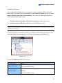
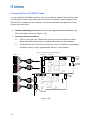
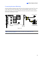
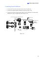
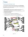
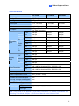
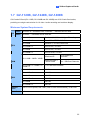
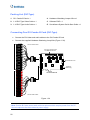
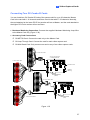
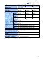
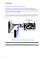
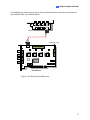
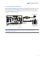
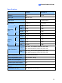
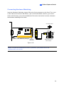
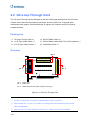
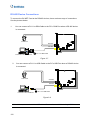
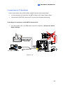
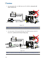
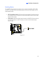
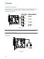
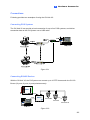
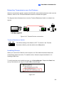
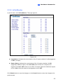
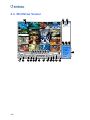
1
Installation Guide V8.5.5.0 Before attempting to connect or operate this product, please read these instructions carefully and save this manual for future use. IGV8550-A © 2012 GeoVision, Inc. All rights reserved. Under the copyright laws, this manual may not be copied, in whole or in part, without the written consent of GeoVision. Every effort has been made to ensure that the information in this manual is accurate. GeoVision, Inc. makes no expressed or implied warranty of any kind and assumes no responsibility for errors or omissions. No liability is assumed for incidental or consequential damages arising from the use of the information or products contained herein. Features and specifications are subject to change without notice. GeoVision, Inc. 9F, No. 246, Sec. 1, Neihu Rd., Neihu District, Taipei, Taiwan Tel: +886-2-8797-8377 Fax: +886-2-8797-8335 http://www.geovision.com.tw Trademarks used in this manual: GeoVision, the GeoVision logo and GV series products are trademarks of GeoVision, Inc. Windows and Windows XP are registered trademarks of Microsoft Corporation. July 2012 Contents Important Notice.....................................................................................1 Important Notice before Using GV-Video Capture Card .....................3 Chapter 1 Video Capture Cards..........................................................6 1.1 GV-SDI-204 ..............................................................................................................7 1.2 GV-5016 .................................................................................................................14 1.3 GV-4008 .................................................................................................................23 1.4 GV-4008A...............................................................................................................32 1.5 GV-3008 .................................................................................................................38 1.6 GV-1120A, 1240A, 1480A ......................................................................................45 1.7 GV-1120B, GV-1240B, GV-1480B .........................................................................55 1.8 GV-1008 .................................................................................................................62 1.9 GV-900A.................................................................................................................69 1.10 GV-650A, GV-800A ..............................................................................................75 1.11 GV-600A...............................................................................................................83 1.12 GV-600B, GV-650B, GV-800B .............................................................................90 1.13 Installing Two Cards .............................................................................................97 1.14 Installing Drivers ...................................................................................................99 1.15 Comparison Chart (H/W Compression)..............................................................100 1.16 Comparison Chart (S/W Compression: Single Card) .........................................105 1.17 Comparison Chart (S/W Compression: Two Cards)...........................................109 Chapter 2 Hardware Accessories...................................................113 2.1 GV-Multi Quad Card .............................................................................................114 2.2 GV-Loop Through Card ........................................................................................118 2.3 GV-NET Card V3.1...............................................................................................121 2.4 GV-NET/IO Card V3.1 ..........................................................................................124 2.5 GV-Hub V2 ...........................................................................................................134 2.6 GV-COM V2 .........................................................................................................138 2.7 GV-I/O 12-In Card V3 ...........................................................................................141 2.8 GV-I/O 12-Out Card V3 ........................................................................................144 2.9 GV-I/O Box (16 Ports) ..........................................................................................147 2.10 GV-I/O Box (8 Ports) ..........................................................................................154 2.11 GV-I/O Box (4 Ports) ..........................................................................................161 i 2.12 Accessing GV-I/O Box over Networks................................................................167 2.13 Installing USB Driver ..........................................................................................178 Chapter 3 Software Installation ......................................................179 3.1 Before You Start ...................................................................................................180 3.2 Installing the System ............................................................................................181 3.3 Program List .........................................................................................................183 Chapter 4 Screen Overview ............................................................185 4.1 Main System.........................................................................................................186 4.2 ViewLog................................................................................................................188 4.3 SingleView Viewer................................................................................................191 4.4 MultiView Viewer ..................................................................................................192 4.5 Center V2 .............................................................................................................194 Troubleshooting .................................................................................196 ii Important Notice GPU Decoding Specifications In V8.5 or later, support for GPU (Graphics Processing Unit) decoding is added to lower the CPU loading and to increase the total frame rate supported by a GV-System. GPU decoding only supports the following software and hardware specifications: Software Specifications Supported Sandy Bridge Ivy Bridge Not Supported 32-Bit Operating System 64-Bit Windows Vista / 7 Windows 7 / Server 2008 R2 Windows 7 GV-System V8.5.0.0 or later V8.5.5.0 or later Resolution 1 MP / 2 MP 1 MP / 2 MP / 3 MP Codec H.264 MPEG4 / MJEPG Stream Single Stream Dual Streams Windows 2000 / XP / Server 2008 CIF / VGA / D1 / 4MP / 5MP Note: To apply GPU decoding, the recommended memory (RAM) requirements is 8 GB or more for 64-bit OS and 3 GB for 32-bit OS. Hardware Specifications Intel chipset with onboard VGA Motherboard Ex: Intel® Q77, Q75, Z77, Z75, H77, B75, Q67, H67, H61, Q65, B65, Z68 Express Chipset. Note: If you want to use an external VGA card, it is required to connect a monitor to the onboard VGA to activate GPU decoding. 1 Multi-Channel Playback Specifications In V8.5 or later, multi-channel playback in ViewLog has been enhanced to improve the smoothness of the video by producing higher frame rate. However, playing back multiple channels at high resolution can increase the CPU loading especially if the GV-System is processing other tasks simultaneously. As a result of the high CPU loading, dropped frames may sometimes occur in recorded video when playing back multiple megapixel channels. To avoid the problem, it is recommended to play back megapixel video in single view. Important Notice before Using GV-Video Capture Card 1. Exclusions: • Currently all GV-Video Capture Cards are not compatible with VIA series, ATI series chipset motherboards. • Currently GV-600(S), GV-650(S), GV-800(S), GV-600A, GV-650A and GV-800A, GV1120, GV-1240, GV-1480 Cards are not compatible with VIA series, ATI series, Intel Sandy Bridge series and Intel Ivy Bridge series chipset motherboards. • Currently GV-3008 Card is not compatible with VIA series, ATI series, NVIDIA series, Intel Sandy Bridge series and Intel Ivy Bridge series chipset motherboards. • If your GV-Video Capture Card or GV-System works in conjunction with GV-Multi Quad Card or GV-Keyboard V1 / V2, note these accessories do not support 64-bit Windows versions. 2. Hard Disk Requirements: • It is strongly recommended to use two separate hard disks. One is for installing Windows operating system and GV-System software, and the other is for storing recorded files. • The total of recording frame rates that you can assign to a single hard disk is listed as below: 2 Frame rate limit in a single hard disk when connecting to analog cameras Software Compression NTSC PAL CIF 960 FPS 800 FPS VGA/D1 480 FPS 400 FPS Turbo VGA 416 FPS 400 FPS Turbo D1 352 FPS 320 FPS Video Resolution (MPEG4) Note: 1. 2. The above data was determined using the default codec MPEG4 and hard disks with average R/W speed above 110 MB/s. The data for Turbo VGA and Turbo D1 was determined using GV-1480A Card. Hardware Compression Video Resolution D1 H.264 NTSC PAL 480 FPS 400 FPS Note: The above data was determined using the default codec H.264, default quality level Q3 and hard disks with average R/W speed above 110 MB/s. Frame rate limit in a single hard disk when connecting to IP cameras Video resolution H.264 Frame Rate MJPEG Bit Rate Frame Rate Bit Rate 5 MP (2560 x 1920) 220 FPS 8.5 Mbit/s 80 FPS 30.4 Mbit/s 4 MP (2048 x 1944) 330 FPS 10.4 Mbit/s 105 FPS 40.53 Mbit/s 3 MP (2048 x 1536) 440 FPS 9.83 Mbit/s 140 FPS 38.67 Mbit/s 2 MP (1920 x 1080) 660 FPS 12.59 Mbit/s 210 FPS 44.93 Mbit/s 1.3 MP (1280 x 1024) 660 FPS 6.16 Mbit/s 300 FPS 32.26 Mbit/s Note: The data above was determined using the bit rate listed above and hard disks with average R/W speed above 110 MB/s. 3 Frame rate limit in a single hard disk when connecting to SDI cameras Hardware Compression Video Resolution H.264 NTSC PAL 1080p 360 FPS 300 FPS 1080i 360 FPS 300 FPS 720p 720 FPS 600 FPS Note: The above data was determined using the default codec H.264, default quality level Q3 and hard disks with average R/W speed above 110 MB/s. The frame rate limit is based on the resolution of video sources. The higher video resolutions the lower frame rates you can assign to a single hard disk. In other words, the higher frame rates you wish to record the more hard disks you need to install. For the information of recording frame rates, you may consult the user’s manual of the GVSystem or the IP camera that you wish to connect to. • The hard disk space required to install GV-System must be at least 1 GB. • To use Advanced Video Analysis, at least 1 GB of memory is required. • To use two or more of the following functions simultaneously, at least 2 GB of memory is required: Advanced Video Analysis, Video Analysis, IP Camera and Pre-Record by Memory. 3. CPU Requirements: • For recording resolution of 640 x 480 or above, Pentium 4 processor with Hyper Threading is required. 4. 4. Default Settings: • For software recording rates, all GV Cards are set to CIF. For hardware recording rates, GV-4008A / 4008 / 3008 Card is set to D1. 5. The Card with PCI-E Interface: • GV-Video Capture Cards with x1 interface support the PCI Express x1, x4, x8 or x16 slot. GV-1120B, GV-1240B, GV-1480B Cards with x4 interface support x4, x8 or x16 slot. 4 6. GV-600A, GV-650A and GV-800A: • Starting from V8.3.2, GV-600 (V4), GV-650 (V4) and GV-800 (V4) are renamed to GV600A, GV-650A and GV-800A. These V4 Cards and A Cards are the same video capture cards. 7. End of Support: • Starting from V8.3, GV-System will not support GV-250 Card, GV-Hybrid DVR (MPEG2) Card and GV-DSP Card. • Starting from V8.3.2, GV-System will not support GV-2004 Card. • Starting from V8.3.2, GV-System will not support MPEG2 codec. • Starting form V8.3.3, GV-System will not support GV-2008 Card. • Starting from V8.4, GV-System will not support Windows 2000. 5 Chapter 1 Video Capture Cards This chapter includes the following information: • Minimum system requirements • Packing list • Connection diagrams • Specifications • Driver installation • Comparison chart 1 Video Capture Cards 1.1 GV-SDI-204 The GV-SDI-204 Card provides up to 4 video channels of HD-SDI cameras, recording up to 120 / 100 fps (NTSC / PAL) in total at 1080p with H.264 hardware compression. You can install up to four GV-SDI-204 Cards for a total of 16 channels. The new technology of resolution is employed to enhance the live image without DSP Overlay. Even in multi views, the image on the largest division view can remain at high-quality resolution without DSP Overlay. Minimum System Requirements OS 32-bit Windows XP / Windows Vista / Windows 7 / Windows Server 2008 64-bit Windows 7 / Windows Server 2008 R2 CPU RAM GV-SDI-204 Core 2 Duo E4400, 2.00 GHz GV-SDI-204 x 2 Core 2 Quad Q9400, 2.66 GHz GV-SDI-204 x 3 Core i3-2130, 3.40 GHz GV-SDI-204 x 4 Core i3-2130, 3.40 GHz GV-SDI-204 2 x 1 GB Dual Channels GV-SDI-204 x 4 HDD GV-SDI-204 500 GB GV-SDI-204 x 4 2 TB Graphic Card AGP or PCI-Express, 800 x 600 (1280 x 1024 recommended), 32bit color DirectX 9.0c Packing List 1. GV-SDI-204 Card x 1 4. USB Dongle x 1 2. SATA Power Converter Cable x 1 5. Software DVD x 1 3. Hardware Watchdog Jumper Wire x 1 6. Surveillance System Quick Start Guide x 1 7 Connecting the GV-SDI-204 Cards Up to four GV-SDI-204 Cards can be connected. GV-SDI-204 Cards can also be installed with other types of GV-Video Capture Cards including GV-900A, GV-800B, GV-650B, GV600B, and GV-1480A / 1240A / 1120A Combo Cards, but the total number of channels cannot exceed 32 channels. • Connect the HD-SDI cameras to the GV-SDI-204 Card using BNC cables. • Using the supplied SATA Power Converter Cable, connect the GV-SDI-204 Card to power supply. • Connect the supplied Hardware Watchdog Jump Wire (Figure 1-2). • After you turn on the computer, the Power LED (D1) and Status LED (D10 and D18) should be lit in green to indicate the card is ready for use. Power LED (D1) Status LED (D10) Hardware Watchdog Video 1 ~ 4 Not Functional Status LED (D18) GV-SDI-204 Card SATA Power Converter Cable Figure 1-1 Note: 1. The GV-SDI-204 Card only works when the supplied USB Dongle is inserted to PC. 2. The connected HD-SDI cameras must have a resolution under 1080p_30, 720p_60 or 1080i_60. The Video Lost message will be displayed when the connected channels have higher resolution. 8 1 Video Capture Cards Connecting Hardware Watchdog Insert the Hardware Watchdog Jumper Wire to the 2-pin connectors on the Card. The (+) pin on the Card must connect to the Reset (+) pin on the motherboard, and the (-) pin on the Card to the Ground (-) pin on the motherboard. Ensure the connection is correct; otherwise the hardware watchdog will not work. When installing multiple capture cards, the Hardware Watchdog can be connected to any of the GV-SDI-204 cards, no matter if the cards are all GV-SDI-204 cards or a combination of GV-SDI-204 cards and other capture cards. If you are installing GV-SDI cards in addition to existing video capture cards and the Hardware Watchdog has already been connected, you do not need to change the connection to a GV-SDI-204 card. Figure 1-2 Note: To locate the motherboard’s Reset (+) pin and (-) pin, please refer to the motherboard’s user manual. 9 Installing Drivers After installing the GV-SDI-204 Card in the computer, insert the software DVD to install GVSeries drivers. The DVD will run automatically and an installation window will pop up. Select Install or Remove GeoVision GV-Series Driver, and select the following two options to install card and USB dongle drivers. • Install or Remove GeoVision GV-Series Card Drivers: installs card drivers. • Install GeoVision USB Device Drivers: installs USB dongle drivers. To verify the drivers are installed correctly, go to Windows Device Manager and see if their entries are listed. The image below is an example of installing one GV-SDI-204 card. Figure 1-3 Expand the DVR-Devices field, you can see: GV-SDI-204 Card Single-card mode Four-card mode 10 Entry GV-SDI-204 GV-Series USB Protector GV-SDI-204 GV-SDI-204 GV-SDI-204 GV-SDI-204 GV-Series USB Protector 1 Video Capture Cards Adjusting the Video Settings in the Main System One distinct feature of GV-SDI-204 Cards is their ability of hardware compression, providing you with higher system performance and DVD recording quality. To take full advantage of GV-SDI-204 Cards, you can adjust the video settings, including the recording quality and frame rate, before running the GV-System. Setting up the video settings of the recorded files: Considering computer performance or recording quality, you may adjust the settings to meet your needs. 1. On the Main System, click the Configure button, select System Configure, select Camera Install, and click Hardware Compression Setup. This dialog box appears. Figure 1-4 2. Select the cameras you want to set up, and click the Configure button. This dialog box appears. Figure 1-5 3. In the Select Hardware-compressed Camera section, select one camera to be configured. 4. Select the recording quality. 11 5. The Enable hardware-compressed data FIFO option is disabled by default. When the option is enabled, the hardware-compressed data from the video IP device, such as IP camera, video server and compact DVR, will be transmitted directly to remote servers instead of being compressed again on the DVR. The remote servers include CMS-related servers and WebCam Server. This feature can decrease the system load of DVR but increase that of remote servers. 6. To use standard H.264 codec in recording, enable Standard codec in the Recording codec format section. 7. To apply the same setting to all cameras, click the Finger button in each section. 8. To access the frame rate settings, on the Main System, click the Configure button, select System Configure, and select Camera Configure. This dialog box appears. Figure 1-6 9. In the Rec Control section, click the Arrow button. The Hardware Rec. Frame Rate Setting dialog box appears. 10. Set the maximum frame rate for motion and non-motion periods to save disk space when possible. 12 1 Video Capture Cards Specifications GV-SDI-204 Interface PCI-E (x1) Input Type BNC Video Input 4 Cams Audio Input N/A 1080p Recording Rate and Display 720p Rate 1080i NTSC 120 fps PAL 100 fps NTSC 240 fps PAL 200 fps NTSC 120 fps PAL 100 fps 1080p 1920 x 1080 H/W 720p 1280 x 720 Video 1080i 1920 x 1080 Resolution 1080p 960 x 540, 480 x 270 S/W Video Compression Format 720p 640 x 360 1080i 960 x 540, 480 x 270 H/W H.264 S/W Geo MPEG4, Geo H.264 Bit Rate Range 10M ~ 20M GV-NET/IO Card Support Yes (Note 2) GV-Multi Quad Card Support No GV-Loop Through Card Support No Dimensions (W x H) 158 x 111 mm / 6.22 x 4.37 in Note: 1. GV-SDI-204 does not support the TV-Out function. 2. To work together with GV-SDI-204, GV-NET/IO Card V3.1 must be set in the I/O Box Mode and connected to the PC through USB or DB9. 13 1.2 GV-5016 The GV-5016 Card provides up to 16 video and 16 audio channels, recording up to 480 / 400 fps (NTSC / PAL) in total with H.264 hardware compression. The new technology of resolution is employed to enhance the live image without DSP Overlay. Even in multi views, the image on the largest division view can remain at high-quality resolution without DSP Overlay. Minimum System Requirements OS 32-bit Windows XP / Windows Vista / Windows 7 / Windows Server 2008 64-bit Windows 7 / Windows Server 2008 R2 CPU RAM GV-5016 Core 2 Quad, 2.4 GHz GV-5016 x 2 Core i5 650, 3.20 GHz GV-5016 2 x 1 GB Dual Channels GV-5016 x 2 HDD GV-5016 500 GB GV-5016 x 2 1 TB Graphic Card AGP or PCI-Express, 800 x 600 (1280 x 1024 recommended), 32bit color DirectX 9.0c Packing List 1. GV-5016 Card x 1 4. USB Dongle x 1 2. 1-16 LFH-Type Audio and Video Cable x 1 5. Software DVD x 1 3. Hardware Watchdog Jumper Wire x 1 6. Surveillance System Quick Start Guide x 1 14 1 Video Capture Cards Connecting One GV-5016 Card • Connect the video and audio cables to the GV-5016 Card. • Connect the supplied Hardware Watchdog Jump Wire (Figure 1-11). • After you turn on the computer, the Power LED (D19) and Status LED (D17) should be lit in green to indicate the card is ready for use. Figure 1-7 When connecting the cable, make sure the cable is connected correctly: • The letter “H” on the connector should be on the same side as the chipsets. H GV-5016 Card Figure 1-8 • The LFH connector on the cable is in the shape of a trapezoid and should match the trapezoid connector on the capture card. GV-5016 Card Cable Figure 1-9 Note: 1. The GV-5016 Card only works when the supplied USB Dongle is inserted to PC. 2. The GV-5016 Card cannot work with microphones which acquire power from the PC. Use microphones which have external power supply. 15 Connecting Two GV-5016 Cards You can install two GV-5016 Cards for a total of 32 channels. Master Card is the card with 116 channels and Slave Card is that with 17-32 channels. Normally, the card attached to the lower PCI-E slot number will act as Master, and the card attached to the higher PCI-E slot number will act as Slave. • Hardware Watchdog Connection: Connect the supplied Hardware Watchdog Jump Wire to the Master Card only (Figure 1-11). Video 1 ~ 16 (Yellow) H GV-5016 Card (Master) Audio 1 ~ 16 (Red) Video 17 ~ 32 (Yellow) Hardware Watchdog GV-5016 Card (Slave) H Audio 17 ~ 32 (Red) Figure 1-10 16 1 Video Capture Cards Connecting Hardware Watchdog Insert the Hardware Watchdog Jumper Wire to the 2-pin connectors on the Card. The (+) pin on the Card must connect to the Reset (+) pin on the motherboard, and the (-) pin on the Card to the Ground (-) pin on the motherboard. Ensure the connection is correct; otherwise the hardware watchdog will not work. PC Reset Switch + + + Hardware Watchdog GV-5016 Card - _ RST PWSW HDD LED Motherboard Front Panel Jumper Figure 1-11 Note: To locate the motherboard’s Reset (+) pin and (-) pin, please refer to the motherboard’s user manual. 17 Installing Drivers After installing the GV-5016 Card in the computer, insert the software DVD to install GVSeries drivers. The DVD will run automatically and an installation window will pop up. Select Install or Remove GeoVision GV-Series Driver, and select the following two options to install card and USB dongle drivers. • Install or Remove GeoVision GV-Series Card Drivers: installs card drivers. • Install GeoVision USB Device Drivers: installs USB dongle drivers. To verify the drivers are installed correctly, go to Windows Device Manager and see if their entries are listed. The image below is an example of installing one GV-5016 card. Figure 1-12 Expand the DVR-Devices field, you can see: GV-5016 Card Entry Single-card mode GV5016 GV-Series USB Protector Two-card mode GV5016 GV5016 GV-Series USB Protector 18 1 Video Capture Cards Adjusting the Video Settings in the Main System One distinct feature of GV-5016 Cards is their ability of hardware compression, providing you with higher system performance and DVD recording quality. To take full advantage of GV-5016 Cards, you can adjust the video settings, including the recording quality and frame rate, before running the GV-System. Setting up the video settings of the recorded files: Considering computer performance or recording quality, you may adjust the settings to meet your needs. 1. On the Main System, click the Configure button, select System Configure, select Camera Install, and click Hardware Compression Setup. This dialog box appears. Figure 1-13 2. Select the cameras you want to set up, and click the Configure button. This dialog box appears. Figure 1-14 19 3. In the Select Hardware-compressed Camera section, select one camera to be configured. 4. Select the recording quality. 5. The Enable hardware-compressed data FIFO option is disabled by default. When the option is enabled, the hardware-compressed data from the video IP device, such as IP camera, video server and compact DVR, will be transmitted directly to remote servers instead of being compressed again on the DVR. The remote servers include CMSrelated servers and WebCam Server. This feature can decrease the system load of DVR but increase that of remote servers. 6. To use standard H.264 codec in recording, enable Standard codec in the Recording codec format section. 7. If you want to apply the same setting to all cameras, click the Finger button in each section. 8. To access the frame rate settings, on the Main System, click the Configure button, select System Configure, and select Camera Configure. This dialog box appears. Figure 1-15 9. In the Rec Control section, click the Arrow button. The Hardware Rec. Frame Rate Setting dialog box appears. 20 1 Video Capture Cards 10. Set the maximum frame rate for motion and non-motion periods so as to save as much disk space as possible. 11. To adjust image quality, in the Video Attributes section, move the sliders to the desired values or click Default to apply default values. Note: The default settings are as follows: Recording Quality is 3, Video Resolution is 704 x 480 (NTSC) or 704 x 576 (PAL), Codec is Geo H.264 and Frame Rate is 30 (NTSC) or 25 (PAL). 21 Specifications GV-5016 GV-5016 x 2 Interface PCI-E (x1) PCI-E (x1) x 2 Input Type LFH Video Input 16 Cams 32 Cams Audio Input 16 Channels 32 Channels NTSC 480 fps 960 fps PAL 400 fps 800 fps NTSC 480 fps 960 fps PAL 400 fps 800 fps H/W 704 x 480 704 x 480 S/W 352 x 240 352 x 240 H/W 704 x 576 704 x 576 S/W 352 x 288 Recording Rate (D1) Display Rate NTSC Video Resolution PAL 352 x 288 Video Compression S/W Geo MPEG4, Geo H264 Format H/W H.264 Audio Compression Format AAC (16 kHz / 16 bit) Bit Rate Range 5M ~ 10M GV-NET/IO Card Support Yes (Note 2) GV-Multi Quad Card Support No GV-Loop Through Card Support No Dimensions (W x H) 168 x 70 mm / 6.61 x 2.75 in Note: 1. GV-5016 does not support the TV-Out function. 2. To work together with GV-5016, GV-NET/IO Card V3.1 must be set in the I/O Box Mode and connected to the PC through USB or DB9. 22 1 Video Capture Cards 1.3 GV-4008 The GV-4008 Card provides up to 8 video and 8 audio channels, recording up to 240 / 200 fps (NTSC / PAL) in total with H.264 hardware compression. The new technology of resolution is employed to enhance the live image of D1 without DSP Overlay. Even in screen divisions, the largest division can remain at the high-quality D1 resolution. Minimum System Requirements OS 32-bit Windows XP / Windows Vista / Windows 7 / Windows Server 2008 64-bit Windows 7 / Windows Server 2008 R2 CPU RAM GV-4008 Core 2 Duo, 2.33 GHz GV-4008 x 2 Core 2 Quad, 2.4 GHz GV-4008 2 x 1 GB Dual Channels GV-4008 x 2 HDD GV-4008 250 GB GV-4008 x 2 500 GB Graphic Card AGP or PCI-Express, 800 x 600 (1280 x 1024 recommended), 32-bit color DirectX 9.0c Power Supply 400 Watts Packing List 1. GV-4008 Card x 1 5. SATA Power Converter Cable x 1 2. 1-8 Cam Audio BNC Cable with BNC 6. USB Dongle x 1 Male to RCA Female Adaptors x 1 3. 1-8 Cam Video BNC Cable x 1 7. Software DVD x 1 8. Surveillance System Quick Start Guide x 1 4. Hardware Watchdog Jumper Wire x1 23 Connecting One GV-4008 Card • Connect the video and audio cables to the GV-4008 Card. • Using the supplied SATA Power Converter Cable, connect the GV-4008 Card to power supply. The Power LED in the top right corner should be lit in green and the 4 status LEDs (D3, D9, D14, D18) in the left corner should be lit in green to indicate the normal functionality. Power LED Status LEDs Reset LED Audio 1~8 Hardware Watchdog GV-4008 Card Video 1~8 SATA Power Converter Cable Figure 1-16 Note: 1. The GV-4008 Card only works when the supplied USB Dongle is inserted to PC. 2. The GV-4008 Card cannot work with microphones which acquire power from the PC. Use microphones which have external power supply. 24 1 Video Capture Cards Connecting Two GV-4008 Cards You can install two GV-4008 Cards for a total of 16 channels. Master Card is the card with 18 channels and Slave Card is that with 9-16 channels. Normally, the card attached to the lower PCI slot number will act as Master, and the card attached to the higher PCI slot number will act as Slave. • Hardware Watchdog Connection: Connect the supplied Hardware Watchdog Jump Wire to the Master Card only (Figure 1-18). • Accessory Card Connections: To work together with GV-4008 Cards, GV-NET/IO Card V3.1 must be set in the I/O Box Mode and connected to the PC through USB or DB9. Hardware Watchdog Audio 1~8 GV-4008 Card (Master) Video 1~8 SATA Power Converter Cable Audio 9-16 GV-4008 Card (Slave) Video 9-16 SATA Power Converter Cable Figure 1-17 25 Connecting Hardware Watchdog Insert the Hardware Watchdog Jumper Wire to the 2-pin connectors on the Card. The (+) pin on the Card must connect to the Reset (+) pin on the motherboard, and the (-) pin on the Card to the Ground (-) pin on the motherboard. Ensure the connection is correct; otherwise the hardware watchdog will be damaged. PC Reset Switch + _ Hardware Watchdog + + - RST PWSW HDD LED Motherboard Front Panel Jumper GV-4008 Card Figure 1-18 Note: To locate the motherboard’s Reset (+) pin and (-) pin, please refer to the motherboard’s user manual. 26 1 Video Capture Cards Installing Drivers After installing the GV-4008 Card in the computer, insert the software DVD to install GVSeries drivers. The DVD will run automatically and an installation window will pop up. Select Install or Remove GeoVision GV-Series Driver, and select the following two options to install card and USB dongle drivers. • Install or Remove GeoVision GV-Series Card Drivers: installs card drivers. • Install GeoVision USB Device Drivers: installs USB dongle drivers. Note: For the installation of two GV-4008 cards, it is required to restart the computer after the driver is installed. To verify the drivers are installed correctly, go to Windows Device Manager and see if their entries are listed. The image below is an example of installing one GV-4008 card. Figure 1-19 Expand the DVR-Devices field, you can see: GV-4008 Card Single-card mode Entry GV4008 GV-Series USB Protector GV4008 Two-card mode GV4008 GV-Series USB Protector 27 Troubleshooting Power Supply Issues When the Reset LED on the top of the Card is flashing red color or the four Status LEDs are not all on, it indicates that the GV-4008 Card is short of power supply. Make sure your power supply is of 400 watts at least. If not, replace it with the power supply of 400 or larger watts. The power supply issues should be solved. Adjusting the Video Settings in the Main System One distinct feature of GV-4008 Cards is their ability of hardware compression, providing you with higher system performance and DVD recording quality. To take full advantage of GV-4008 Cards, you can adjust the video settings, including the recording quality and frame rate, before running the GV-System. Setting up the video settings of the recorded files: Considering computer performance or recording quality, you may adjust the settings to meet your needs. 1. On the Main System, click the Configure button, select System Configure, select Camera Install, and click Hardware Compression Setup. This dialog box appears. Figure 1-20 28 1 Video Capture Cards 2. Select the cameras you want to set up, and click the Configure button. This dialog box appears. Figure 1-21 3. In the Select Hardware-compressed Camera section, select one camera to be configured. 4. Select the recording quality. 5. The Enable hardware-compressed data FIFO option is disabled by default. When the option is enabled, the hardware-compressed data from the video IP device, such as IP camera, video server and compact DVR, will be transmitted directly to remote servers instead of being compressed again on the DVR. The remote servers include CMSrelated servers and WebCam Server. This feature can decrease the system load of DVR but increase that of remote servers. 6. To use standard H.264 codec in recording, enable Standard codec in the Recording codec format section. 7. If you want to apply the same setting to all cameras, click the Finger button in each section. 29 8. To access the frame rate settings, on the Main System, click the Configure button, select System Configure, and select Camera Configure. This dialog box appears. Figure 1-22 9. In the Rec Control section, click the Arrow button. The Hardware Rec. Frame Rate Setting dialog box appears. 10. Set the maximum frame rate for motion and non-motion periods so as to save as much disk space as possible. 11. To adjust image quality, in the Video Attributes section, move the sliders to the desired values or click Default to apply default values. Note: The default settings are as follows: Recording Quality is 3, Video Resolution is 704 x 480 (NTSC) or 704 x 576 (PAL), Codec is Geo H.264 and Frame Rate is 30 (NTSC) or 25 (PAL). 30 1 Video Capture Cards Specifications GV-4008 GV-4008 x 2 Interface PCI-E (x1) PCI-E (x1) x 2 Input Type DVI Video Input 8 Cams 16 Cams Audio Input 8 Channels 16 Channels Recording Rate NTSC 240 fps 480 fps (D1) PAL 200 fps 400 fps NTSC 240 fps 480 fps PAL 200 fps 400 fps H/W 704 x 480 704 x 480 S/W 352 x 240 352 x 240 H/W 704 x 576 704 x 576 S/W 352 x 288 352 x 288 Display Rate NTSC Video Resolution PAL Video Compression S/W Geo MPEG4, Geo H264 Format H/W H.264 Audio Compression Format AAC (16 kHz / 16 bit) Bit Rate Range 2.5M ~ 5M GV-NET/IO Card Support Yes (Note2) GV-Multi Quad Card Support No Dimensions (W x H) 169 x 99 mm / 6.65 x 3.9 in Note: 1. GV-4008 does not support the TV-Out function. 2. To work together with GV-4008, GV-NET/IO Card V3.1 must be set in the I/O Box Mode and connected to the PC through USB or DB9. 3. In screen divisions, the largest division is set to D1 resolution and the other divisions to CIF resolution. 31 1.4 GV-4008A The GV-4008A Card provides up to 8 video and 8 audio channels, recording up to 240 / 200 fps (NTSC / PAL) in total with H.264 hardware compression. The new technology of resolution is employed to enhance the live image without DSP Overlay. Even in multi views, the image on the largest division view can remain at the high-quality resolution without DSP Overlay. Minimum System Requirements OS 32-bit Windows XP / Windows Vista / Windows 7 / Windows Server 2008 64-bit Windows 7 / Windows Server 2008 R2 CPU RAM GV-4008A Core 2 Duo, 2.33 GHz GV-4008A x 2 Core 2 Quad, 2.4 GHz GV-4008A 2 x 1 GB Dual Channels GV-4008A x 2 HDD Graphic Card GV-4008A 250 GB GV-4008A x 2 500 GB AGP or PCI-Express, 800 x 600 (1280 x 1024 recommended), 32bit color DirectX 9.0c Power Supply 400 Watts Packing List 1. GV-4008A Card x 1 5. Internal Power Y Cable x 1 2. 1-8 DVI-Type Audio Cable x 1 6. USB Dongle x 1 3. 1-8 DVI-Type Video Cable x 1 7. Software DVD x 1 4. Hardware Watchdog Jumper Wire x 1 8. Surveillance System Quick Start Guide x 1 32 1 Video Capture Cards Connecting One GV-4008A Card • Connect the video and audio cables to the GV-4008A Card. • Connect the supplied Hardware Watchdog Jump Wire (Figure 1-16). • Connect the computer’s internal power supply to the GV-4008A Card. The LEDs (D17, D19, D21, D23) should be lit in green to indicate the card is ready for use. Video 1 ~ 8 (Yellow) GV-Loop Through Card / GV-Multi Quad Card Debug Port Video 5 ~ 8 Video 1 ~ 4 Internal Power Y Cable Hardware Watchdog LEDs ON 1 2 Audio 1 ~ 8 (Red) GV-4008A Card Figure 1-23 Note: 1. The GV-4008A Card only works when the supplied USB Dongle is inserted to PC. 2. The GV-4008A Card cannot work with microphones which acquire power from the PC. Use microphones which have external power supply. 33 Connecting Two GV-4008A Cards You can install two GV-4008A Cards for a total of 16 channels. Master Card is the card with 1-8 channels and Slave Card is that with 9-16 channels. Normally, the card attached to the lower PCI-E slot number will act as Master, and the card attached to the higher PCI-E slot number will act as Slave. • Hardware Watchdog Connection: Connect the supplied Hardware Watchdog Jump Wire to the Master Card only (Figure 1-16). • Accessory Card Connections: GV-Loop Through Card: Connect the card to two 10-pin connectors on each Master and Slave Card by using a supplied cable with four 10-pin headers. GV-Multi Quad Card: Connect the card to two 10-pin connectors on each Master and Slave Card by using a supplied cable with four 10-pin headers. GV-Loop Through Card / GV-Multi Quad Card Video 1 ~ 8 Video 5 ~ 8 Video 1 ~ 4 Internal Power Y Cable Hardware Watchdog GV-4008A Card (Master) ON 1 2 Audio 1 ~ 8 Video 9 ~ 16 Video 13 ~ 16 Internal Power Y Cable Video 9 ~ 12 GV-4008A Card (Slave) ON 1 2 Audio 9 ~ 16 Figure 1-24 34 1 Video Capture Cards Connecting Hardware Watchdog Insert the Hardware Watchdog Jumper Wire to the 2-pin connectors on the Card. The (+) pin on the Card must connect to the Reset (+) pin on the motherboard, and the (-) pin on the Card to the Ground (-) pin on the motherboard. Ensure the connection is correct; otherwise the hardware watchdog will not work. PC Reset Switch + + _ + RST PWSW HDD LED ON 1 2 GV- 4008A Card Hardware Watchdog Motherboard Front Panel Jumper Figure 1-25 Note: To locate the motherboard’s Reset (+) pin and (-) pin, please refer to the motherboard’s user manual. 35 Installing Drivers After installing the GV-4008A Card in the computer, insert the software DVD to install GVSeries drivers. The DVD will run automatically and an installation window will pop up. Select Install or Remove GeoVision GV-Series Driver, and select the following two options to install card and USB dongle drivers. • Install or Remove GeoVision GV-Series Card Drivers: installs card drivers. • Install GeoVision USB Device Drivers: installs USB dongle drivers. To verify the drivers are installed correctly, go to Windows Device Manager and see if their entries are listed. Expand the DVR-Devices field, you can see: GV-4008A Card Single-card mode Entry GV4008(A) GV-Series USB Protector GV4008(A) Two-card mode GV4008(A) GV-Series USB Protector Adjusting the Video Settings in the Main System One distinct feature of GV-4008A Cards is their ability of hardware compression, providing you with higher system performance and DVD recording quality. To take full advantage of GV-4008A Cards, you can adjust the video settings, including the recording quality and frame rate, before running the GV-System. For details on adjusting the video settings, see Setting up the video settings of the recorded files in 1.1 4008 Card. 36 1 Video Capture Cards Specifications GV-4008A GV-4008A x 2 Interface PCI-E (x1) PCI-E (x1) x 2 Input Type DVI Video Input 8 Cams 16 Cams Audio Input 8 Channels 16 Channels Recording Rate NTSC 240 fps 480 fps (D1) PAL 200 fps 400 fps NTSC 240 fps 480 fps PAL 200 fps 400 fps H/W 704 x 480 704 x 480 S/W 352 x 240 352 x 240 H/W 704 x 576 704 x 576 S/W 352 x 288 Display Rate NTSC Video Resolution PAL Video 352 x 288 S/W Geo MPEG4, Geo H264 H/W H.264 Compression Format Audio Compression Format AAC (16 kHz / 16 bit) Bit Rate Range 2.5M ~ 5M GV-NET/IO Card Support Yes (Note 2) GV-Multi Quad Card Support Yes GV-Loop Through Card Support Yes Dimensions (W x H) 169 x 112 mm / 6.65 x 4.41 in Note: 1. GV-4008A does not support the TV-Out function. 2. To work together with GV-4008A, GV-NET/IO Card V3.1 must be set in the I/O Box Mode and connected to the PC through USB or DB9. 37 1.5 GV-3008 The GV-3008 Card provides up to 8 video and 8 audio channels, recording up to 240 / 200 fps (NTSC / PAL) in total with H.264 hardware compression. The GV-3008 Card provides the high-resolution live image with DSP Overlay. Even in multi views, the image on the largest division view can remain at the high-quality resolution. Minimum System Requirements OS 32-bit Windows XP / Windows Vista / Windows 7 / Windows Server 2008 64-bit Windows 7 / Windows Server 2008 R2 CPU RAM HDD GV-3008 Core 2 Duo, 2.33 GHz GV-3008 x 2 Core 2 Quad, 2.4 GHz GV-3008 GV-3008 x 2 2 x 1 GB Dual Channels GV-3008 250 GB GV-3008 x 2 500 GB Graphic Card AGP or PCI-Express, 800 x 600 (1280 x 1024 recommended), 32bit color DirectX 9.0c Power Supply 400 Watts Packing List 1. GV-3008 Card x 1 4. Hardware Watchdog Jumper Wire x1 2. 1-4 D-Type Video and Audio Cable x 1 5. Software DVD x 1 3. 5-8 D-Type Video and Audio Cable x 1 6. Surveillance System Quick Start Guide x 1 38 1 Video Capture Cards Connecting One GV-3008 Card • Connect the D-Type video and audio cables to the GV-3008 Card. • Connect the supplied Hardware Watchdog Jump Wire (Figure 1-28). • Connect the computer’s internal power supply to the GV-3008 Card. The Power LED should be lit in green to indicate the card is ready for use. GV-Loop Through Card / GV-Multi Quad Card Power LED Video 5~8 Video 1~4 Video/Audio 1~4 GV-NET/IO Card GV 3008 - 8 Hardware Watchdog Jumper Wire 3008 Video/Audio 5~8 GV-3008 Card Internal Power Y Cable Figure 1-26 39 Connecting Two GV-3008 Cards You can install two GV-3008 Cards for a total of 16 channels. Master Card is the card with 18 channels and Slave Card is that with 9-16 channels. The Master and Slave cards can be distinguished by the labels on cards, as shown below: Master Card: Slave Card: IMPORTANT: 1. The Slave Cards cannot work alone. They need to work in conjunction with the Master Cards. 2. If both GV-3008 Cards are Master Cards, it is required to identify which are Master and Slave by the PCI-E slot number. Normally, the card attached to the lower PCI-E slot number will act as Master, and the card attached to the higher PCI-E slot number will act as Slave. • Hardware Watchdog Connection: Connect the supplied Hardware Watchdog Jump Wire to the Master Card only (Figure 1-28). • Accessory Card Connections: GV-NET/IO Card: Connect the card only to the Master Card. GV-Loop Through Card: Connect the card to two 10-pin connectors on each Master and Slave Card by using a supplied cable with four 10-pin headers. GV-Multi Quad Card: Connect the card to two 10-pin connectors on each Master and Slave Card by using a supplied cable with four 10-pin headers. 40 Video Capture Cards 1 GV-Loop Through Card / GV-Multi Quad Card Video 5 ~ 8 Video 1 ~ 4 Video/Audio 1~4 GV-NET/IO Card GV 3008 - 8 Hardware Watchdog Jumper Wire 3008 GV-3008 Card (Master) Internal Power Y Cable Video/Audio 5~8 Video/Audio 9~12 Video 9 ~ 12 Video 13 ~ 16 GV 3008 - 8 3008 GV-3008 Card (Slave) Internal Power Y Cable Video/Audio 13~16 Figure 1-27 41 Connecting Hardware Watchdog To restart the computer automatically by the hardware watchdog on the GV-Video Capture Card, a connection needs to be made from the card to the motherboard. 1. Using the supplied jumper wire, connect the reset jumper pins on the card and on the motherboard. PC Reset Switch GV 3008 - 8 3008 GV-3008 Card Hardware Watchdog RST PWSW HDD LED Motherboard Front Panel Jumper Figure 1-28 2. If the computer has a reset switch, the switch’s jumper wire should already be connected to the motherboard’s reset jumper pins. Remove the switch wire from the motherboard and connect it to the reset jumper pins on the card. 42 1 Video Capture Cards Installing Drivers After installing the GV-3008 Card in the computer, insert the software DVD to install GVSeries drivers. The DVD will run automatically and an installation window will pop up. Select Install or Remove GeoVision GV-Series Driver, and select Install or Remove GeoVision GV-Series Card Drivers to install card drivers. To verify the drivers are installed correctly, go to Windows Device Manager and see if their entries are listed. Expand the DVR-Devices field, you can see: GV-3008 Card Entry Single-card mode Two Master Cards Two-card mode One Master and Slave Card GV3008 Capture GV3008 Encode #1 GV3008 Encode #2 GV3008 Capture GV3008 Capture GV3008 Encode #1 GV3008 Encode #1 GV3008 Encode #2 GV3008 Encode #2 GV3008 Capture GV3008 Capture GV3008 Encode #1 GV3008 Encode #2 GV3008 Encode #3 GV3008 Encode #4 Adjusting the Video Settings in the Main System One distinct feature of GV-3008 Cards is their ability of hardware compression, providing you with higher system performance and DVD recording quality. To take full advantage of GV-3008 Cards, you can adjust the video settings, including the recording quality and frame rate, before running the GV-System. For details on adjusting the video settings, see Setting up the video settings of the recorded files in 1.1 4008 Card. 43 Specifications GV-3008 GV-3008 x 2 Interface PCI-E (x1) PCI-E (x1) x 2 Input Type D-Type Video Input 8 Cams 16 Cams Audio Input 8 Channels 16 Channels NTSC 240 fps 480 fps PAL 200 fps 400 fps NTSC 240 fps 480 fps PAL 200 fps 400 fps H/W 704 x 480 704 x 480 S/W 352 x 240 352 x 240 H/W 704 x 576 704 x 576 S/W 352 x 288 352 x 288 Recording Rate (D1) Display Rate NTSC Video Resolution PAL Video Compression S/W Geo MPEG4, Geo H264 Format H/W H.264 Audio Compression Format AAC (16 kHz / 16 bit) Bit Rate Range 2.5M ~ 10M GV-NET/IO Card Support Yes GV-Multi Quad Card Support Yes GV-Loop Through Card Support Yes Dimensions (W x H) 180 x 112 mm / 7.09 x 4.41 in Note: GV-3008 does not support the TV-Out function. 44 1 Video Capture Cards 1.6 GV-1120A, 1240A, 1480A GV-Combo A Card (GV-1120A, GV-1240A and GV-1480A) are the three-in-one combo cards, providing one single card solution for 16 video / audio recording, real-time display and TV-out display. Minimum System Requirements OS 32-bit Windows XP / Windows Vista / Windows 7 / Windows Server 2008 64-bit Windows 7 / Windows Server 2008 R2 GV-1120A GV-1120A x 2 GV-1240A CPU GV-1240A x 2 GV-1480A GV-1480A x 2 GV-1120A / 1240A / 1480A RAM GV-1120A x 2 / 1240A x 2 / 1480A x 2 HDD Pentium 4, 3.0 GHz with Hyper Threading Turbo Mode: Pentium 4, 3.0 GHz, Dual Core Pentium 4, 3.0 GHz, Dual Core Turbo Mode: Core 2 Quad, 2.4 GHz Pentium 4, 3.0 GHz, Dual Core Turbo Mode: Core 2 Duo, 3.0 GHz Core 2 Duo, 2.53 GHz Turbo Mode: Core 2 Quad, 2.8 GHz Core 2 Duo, 3.0 GHz Turbo Mode: Core 2 Quad, 2.4 GHz Core 2 Quad, 2.4 GHz Turbo Mode: Core i7-920, 2.66 GHz Windows XP 2 x 512 MB Dual Channels Windows Vista / 7 / Server 2008 2 x 1 GB Dual Channels 2 x 1 GB Dual Channels GV-1120A 80 GB / Turbo Mode: 120 GB GV-1120 A x 2 160 GB / Turbo Mode: 250 GB GV-1240A 120 GB / Turbo Mode: 160 GB GV-1240A x 2 250 GB / Turbo Mode: 320 GB GV-1480A 250 GB / Turbo Mode: 320 GB GV-1480A x 2 500 GB / Turbo Mode: 750 GB Graphic Card AGP or PCI-Express, 800 x 600 (1280 x 1024 recommended), 32-bit color DirectX 9.0c 45 Packing List (D-Type) 1. GV-Combo A Card x 1 6. 9-16 D-Type Audio Cable x 1 2. Audio Extension Card x 1 7. Internal Power Y Cable x 1 3. 1-8 D-Type Video Cable x 1 8. Hardware Watchdog Jumper Wire x 1 4. 9-16 D-Type Video Cable x 1 9. Software DVD x 1 5. 1-8 D-Type Audio Cable x 1 10. Surveillance System Quick Start Guide x 1 Packing List (DVI-Type) 1. GV- Combo A Card x 1 5. Hardware Watchdog Jumper Wire x 1 2. 1-16 DVI-Type Video plus TV Out Cable x 1 6. Software DVD x 1 3. 1-16 DVI-Type Audio Cable x 1 7. Surveillance System Quick Start Guide x 1 4. Internal Power Y Cable x 1 46 1 Video Capture Cards Connecting One GV-Combo A Card (D-Type) • Plug the Audio Extension Card in the assigned connectors on the GV-Combo A Card. • Connect D-Type video and audio cables to the GV-Combo A Card and Audio Extension Card respectively. • Connect the supplied Hardware Watchdog Jump Wire (Figure 1-33). • Connect the PC’s internal power supply to the GV-Combo A Card. • Connect the TV monitor to the GV-Combo A Card if needed. Video 1~8 TV Monitor GV-Loop Through Card / GV-Multi Quad Card GV-NET/IO Card Hardware Watchdog 1-8 D-Type Video Cable 4 Video 9~16 2 3 1 GV-Combo A Card 9-16 D-Type Video Cable Internal Power Y Cable Audio 1~8 1-8 D-Type Audio Cable 1 2 3 Audio 9~16 9-16 D-Type Audio Cable 4 Audio Extension Card Figure 1-29 Note: The Card only works when it connects to PC’s power supply using the supplied Internal Power Y Cable. 47 Connecting One GV-Combo A Card (DVI-Type) • Connect the DVI video and audio cables to the GV-Combo A Card. • Connect the supplied Hardware Watchdog Jump Wire (Figure 1-33). • Connect the PC’s internal power supply to the GV-Combo A Card. • Connect the DVI TV Out cable to the TV monitor if needed. 1-16 DVI Video Cable DVI TV Out Cable TV Monitor GV-Loop Through Card / GV-NET/IO Card GV-Multi Quad Card Hardware Watchdog GV-Combo A Card Internal Power Y Cable 1-16 DVI Audio Cable Figure 1-30 Note: The Card only works when it connects to PC’s power supply using the supplied Internal Power Y Cable. 48 1 Video Capture Cards Connecting GV-NET/IO Card to GV-Combo A Card Connect the GV-NET/IO Card to the 20-pin GV-NET/IO port on the GV-Combo A Card. Some GV-Combo A Cards are built in two 20-pin ports. Ensure to connect the GV-NET/IO Card to the correct port as illustrated below. GV-NET/IO Card O N 1 O N O 11N2 O N 20-Pin Ribbon Cable Debug Port 1 GV-NET/IO Port GV-Combo A Card Figure 1-31 Note: If the GV-NET/IO Card is connected to the Debug port, it may lead to the GV-NET/IO Card to be damaged, or the GV-Combo A Card to burn out, causing Video Lost or an error message of “can’t find keypro” to pop up. 49 Connecting Two GV-Combo A Cards You can install two GV-Combo A Cards of the same model for up to 32 channels. Master Card is the card with 1-16 channels and Slave Card is that with 17-32 channels. Normally, the card attached to the lower PCI-E slot number will act as Master, and the card attached to the higher PCI-E slot number will act as Slave. • TV Output Connection: The RCA connector in the Master Card is for displaying 1-16 channels, and the one in the Slave Card is for displaying 17-32 channels. • Hardware Watchdog Connection: Connect the supplied Hardware Watchdog Jump Wire to the Master Card only (Figure 1-33). • Accessory Card Connections: GV-NET/IO Card: Connect the card only to the Master Card. GV-Loop Through Card: Connect the card for each video capture card. GV-Multi Quad Card: Only connect one card to any of two video capture cards. Audio Extension C ard 1 2 1-8 D -Type Audio Cable 3 TV Monitor 4 1-8 D -Type Video Cable GV-NET/IO Card GV-Loop Through Card / GV-Multi Quad Card Hardware 4 2 GV-Combo A Card (Master) 3 9-16 D-Type Video Cable T V Monitor 25-32 D-Type Video Cable 9-16 D- Type Audio Cable 1 4 2 17-24 D-Type Video Cable Internal Pow er Y Cable Watc hdog Jum p Wire GV-C ombo A Card (Slave ) Hardware Watchdog J um p Wire 3 Internal Power Y Cable 1 Audio Extension Car d 17-24 D-T ype Audio Cable 1 2 3 4 Figure1-32 50 25-32 D-T ype Audio Cable 1 Video Capture Cards Connecting Hardware Watchdog Insert the Hardware Watchdog Jumper Wire to the 2-pin connectors on the Card and on the motherboard as illustrated below. Ensure the connection is correct; otherwise the hardware watchdog will not work. PC Reset Switch GV-Combo A Card Hardware Watchdog RST PWSW HDD LED Motherboard Front Panel Jumper Figure 1-33 51 Installing Drivers After installing the GV-Combo A Card in the computer, insert the software DVD. The DVD will run automatically and an installation window will pop up. Select Install or Remove GeoVision GV-Series Driver, and select Install or Remove GeoVision GV-Series Card Drivers to install card drivers. To verify the drivers are installed correctly, go to Windows Device Manager and see if their entries are listed. Expand the DVR-Devices field, you can see: Card Model Entry Single-card mode GV-1120A Two-card mode Single-card mode GV-1240A Two-card mode Single-card mode GV-1480A Two-card mode 52 GV1480A/GV1240A/GV1248A/GV1120A/GV1008 GV1480A/GV1240A/GV1248A/GV1120A/GV1008 GV1480A/GV1240A/GV1248A/GV1120A/GV1008 GV1480A/GV1240A/GV1248A/GV1120A/GV1008 GV1480A/GV1240A/GV1248A/GV1120A/GV1008 GV1480A/GV1240A/GV1248A/GV1120A/GV1008 GV1480A/GV1240A/GV1248A/GV1120A/GV1008 GV1480A/GV1240A/GV1248A/GV1120A/GV1008 GV1480A/GV1240A/GV1248A/GV1120A/GV1008 1 Video Capture Cards Specifications GV-1120A GV-1240A GV-1480A Interface Type PCI-E (x1) Input Type D-Type, DVI Video Input 8, 12, 16 Cams 8, 16 Cams 16 Cams Audio Input 8, 12, 16 Channels 8, 16 Channels 16 Channels TV Output D-Type: RCA Connector DVI: BNC Connector NTSC 120 fps 240 fps 480 fps PAL 100 fps 200 fps 400 fps NTSC 80 fps 120 fps 240 fps PAL 72 fps 100 fps 200 fps Turbo VGA NTSC 120 fps 240 fps 416 fps PAL 100 fps 200 fps 400 fps Turbo D1 NTSC 120 fps 240 fps 352 fps PAL 100 fps 200 fps 320 fps NTSC 480 fps PAL 400 fps NTSC 480 fps PAL 400 fps CIF D1 Recording Rate CIF Display Rate D1 NTSC Video Resolution PAL 704 x 480, 704 x 480 De-interlace, 640 x 480, 640 x 480 De-interlace, 352 x 240, 320 x 240 704 x 576, 704 x 576 De-interlace, 640 x 480, 640 x 480 De-interlace, 352 x 288, 320 x 240 Video Compression Format Geo MPEG4, Geo H264 Audio Compression Format AAC (16 kHz / 16 bit) GV-Multi Quad Card Support Yes GV-Loop Through Card Support Yes GV-NET/IO Card Support Yes Dimensions D-Type 179 x 112 mm / 7.04 x 4.41 in DVI-Type Note: Turbo Mode is only applied in VGA and D1 resolutions. To activate Turbo Mode, see Activating Turbo Mode, Chapter 1, DVR User’s Manual on the Software DVD. 53 GV-1120A x 2 Interface Type PCI-E (x1) x 2 Input Type D-Type, DVI 32 Channels NTSC 240 fps 480 fps 960 fps PAL 200 fps 400 fps 800 fps NTSC 160 fps 240 fps 480 fps PAL 144 fps 200 fps 400 fps Turbo VGA NTSC 240 fps 480 fps 832 fps PAL 200 fps 400 fps 800 fps Turbo D1 NTSC 240 fps 480 fps 704 fps PAL 200 fps 400 fps 640 fps NTSC 960 fps PAL 800 fps NTSC 960 fps PAL 800 fps Audio Input TV Output CIF D1 CIF Display Rate D1 NTSC Video Resolution PAL Geo MPEG4, Geo H264 Audio Compression Format AAC (16 kHz / 16 bit) GV-Multi Quad Card Support Yes GV-Loop Through Card Support Yes GV-NET/IO Card Support Yes D-Type DVI-Type 32 Cams 704 x 480, 704 x 480 De-interlace, 640 x 480, 640 x 480 De-interlace, 352 x 240, 320 x 240 704 x 576, 704 x 576 De-interlace, 640 x 480, 640 x 480 De-interlace, 352 x 288, 320 x 240 Video Compression Format Dimensions GV-1480A x 2 16, 20, 24, 28, 32 16, 24, 32 Cams Cams 16, 20, 24, 28, 32 16, 24, 32 Channels Channels D-Type: RCA Connector DVI: BNC Connector Video Input Recording Rate GV-1240A x 2 179 x 112 mm / 7.04 x 4.41 in Note: Turbo Mode is only applied in VGA and D1 resolutions. To activate Turbo Mode, see Activating Turbo Mode, Chapter 1, DVR User’s Manual on the Software DVD. 54 1 Video Capture Cards 1.7 GV-1120B, GV-1240B, GV-1480B GV-Combo B Card (GV-1120B, GV-1240B and GV-1480B) are of GV-Comb Card series, providing one single card solution for 16 video / audio recording and real-time display. Minimum System Requirements OS 32-bit Windows XP / Windows Vista / Windows 7 / Windows Server 2008 64-bit Windows 7 / Windows Server 2008 R2 CPU GV-1120B Pentium 4, 3.0 GHz with Hyper Threading GV-1120B x 2 Core 2 Duo, E7200, 2.53 GHz GV-1240B Pentium 4, 3.0 GHz, Dual Core GV-1240B x 2 Core 2 Duo, 3.0 GHz GV-1480B Core 2 Duo, 3.0 GHz GV-1480B x 2 Core 2 Quad, 2.4 GHz Windows XP GV-1120B / 1240B / 1480B RAM GV-1120B x 2 / 1240B x 2 / 1480B x 2 HDD Windows Vista / 7 / Server 2008 2 x 512 MB Dual Channels 2 x 1 GB Dual Channels 2 x 1 GB Dual Channels GV-1120B 80 GB GV-1120B x 2 160 GB GV-1240B 120 GB GV-1240B x 2 250 GB GV-1480B 250 GB GV-1480B x 2 500 GB Graphic Card AGP or PCI-Express, 800 x 600 (1280 x 1024 recommended), 32-bit color DirectX 9.0c 55 Packing List (DVI-Type) 1. GV- Combo B Card x 1 4. Hardware Watchdog Jumper Wire x 1 2. 1-16 DVI-Type Video Cable x 1 5. Software DVD x 1 3. 1-16 DVI-Type Audio Cable x 1 6. Surveillance System Quick Start Guide x 1 Connecting One GV-Combo B Card (DVI-Type) • Connect the DVI video and audio cables to the GV-Combo B Card. • Connect the supplied Hardware Watchdog Jump Wire (Figure 1-36). 1-16 DVI Video Cable GV-Loop Through Card / GV-Multi Quad Card GV-NET/IO Card Hardware Watchdog GV-Combo B Card 1-16 DVI Audio Cable Figure 1-34 Note: Combo B Cards cannot work with microphones which acquire power from the PC. Use microphones that have external power supply. 56 1 Video Capture Cards Connecting Two GV-Combo B Cards You can install two GV-Combo B Cards of the same model for up to 32 channels. Master Card is the card with 1-16 channels and Slave Card is that with 17-32 channels. Normally, the card attached to the lower PCI-E slot number will act as Master, and the card attached to the higher PCI-E slot number will act as Slave. • Hardware Watchdog Connection: Connect the supplied Hardware Watchdog Jump Wire to the Master Card only (Figure 1-36). • Accessory Card Connections: GV-NET/IO Card: Connect the card only to the Master Card. GV-Loop Through Card: Connect the card for each video capture card. GV-Multi Quad Card: Only connect one card to any of two video capture cards. 1-16 DVI Video Cable GV-Loop Through Card / GV-Multi Quad Card 1-16 DVI Audio Cable GV-NET/IO Card Hardware Watchdog GV-Combo B Card (Master) 17-32 DVI Video Cable 17-32 DVI Audio Cable GV-Combo B Card (Slave) Figure 1-35 57 Connecting Hardware Watchdog Insert the Hardware Watchdog Jumper Wire to the 2-pin connectors on the Card and on the motherboard as illustrated below. Ensure the connection is correct; otherwise the hardware watchdog will not work. PC Reset Switch Hardware Watchdog RST PWSW HDD LED GV-Combo B Card Motherboard Front Panel Jumper Figure 1-36 58 1 Video Capture Cards Installing Drivers After installing the GV-Combo B Card in the computer, insert the software DVD. The DVD will run automatically and an installation window will pop up. Select Install or Remove GeoVision GV-Series Driver, and select Install or Remove GeoVision GV-Series Card Drivers to install card drivers. To verify the drivers are installed correctly, go to Windows Device Manager and see if their entries are listed. The image below is an example of installing one GV-Combo B card. Figure 1-37 Expand the DVR-Devices field, you can see: Card Model Entry Single-card mode GV-1120B Audio #1~#16 GV-1120B Video #1~#16 Two-card mode GV-1120B Audio #1~#16 GV-1120B Audio #1~#16 GV-1120B Video #1~#16 GV-1120B Video #1~#16 Single-card mode GV-1240B Audio #1~#16 GV-1240B Video #1~#16 Two-card mode GV-1240B Audio #1~#16 GV-1240B Audio #1~#16 GV-1240B Video #1~#16 GV-1240B Video #1~#16 Single-card mode GV-1480B Audio #1~#16 GV-1480B Video #1~#16 Two-card mode GV-1480B Audio #1~#16 GV-1480B Audio #1~#16 GV-1480B Video #1~#16 GV-1480B Video #1~#16 GV-1120B GV-1240B GV-1480B 59 Specifications GV-1120B GV-1240B GV-1480B Interface Type PCI-E (x4) Input Type DVI Video Input 16 Cams 16 Cams 16 Cams Audio Input 16 Channels 16 Channels 16 Channels NTSC 120 fps 240 fps 480 fps PAL 100 fps 200 fps 400 fps NTSC 120 fps 240 fps 480 fps PAL 100 fps 200 fps 400 fps NTSC 480 fps PAL 400 fps NTSC 480 fps PAL 400 fps CIF Recording Rate D1 CIF Display Rate D1 NTSC Video Resolution PAL 704 x 480, 704 x 480 De-interlace, 640 x 480, 640 x 480 De-interlace, 352 x 240, 320 x 240 704 x 576, 704 x 576 De-interlace, 640 x 480, 640 x 480 De-interlace, 352 x 288, 320 x 240 Video Compression Format Geo MPEG4, Geo H264 Audio Compression Format AAC (16 kHz / 16 bit) GV-Multi Quad Card Support Yes GV-Loop Through Card Support Yes GV-NET/IO Card Support Yes Dimensions 60 DVI-Type 156 x 111 mm / 6.14 x 4.37 in 1 GV-1120B x 2 Video Capture Cards GV-1240B x 2 GV-1480B x 2 Interface Type PCI-E (x4) x 2 Input Type DVI Video Input 32 Cams 32 Cams 32 Cams Audio Input 32 Channels 32 Channels 32 Channels NTSC 240 fps 480 fps 960 fps PAL 200 fps 400 fps 800 fps NTSC 240 fps 480 fps 960 fps PAL 200 fps 400 fps 800 fps NTSC 960 fps PAL 800 fps NTSC 960 fps PAL 800 fps CIF Recording Rate D1 CIF Display Rate D1 NTSC Video Resolution PAL 704 x 480, 704 x 480 De-interlace, 640 x 480, 640 x 480 De-interlace, 352 x 240, 320 x 240 704 x 576, 704 x 576 De-interlace, 640 x 480, 640 x 480 De-interlace, 352 x 288, 320 x 240 Video Compression Format Geo MPEG4, Geo H264 Audio Compression Format AAC (16 kHz / 16 bit) GV-Multi Quad Card Support Yes GV-Loop Through Card Support Yes GV-NET/IO Card Support Yes Dimensions 156 x 111 mm / 6.14 x 4.37 in DVI-Type 61 1.8 GV-1008 The GV-1008, as a three-in-one combo card, provides one single card solution for 8 video / audio recording, real-time display and TV-out display. The Card can record each channel at D1 in real time or 30 fps. When the two Cards are installed in the system, it can be utilized to provide a single TV-out display of 16 cameras and maintain a high recording rate of 480 fps at D1 resolution. Minimum System Requirements 32-bit Windows XP / Windows Vista / Windows 7 / Windows Server 2008 64-bit Windows 7 / Windows Server 2008 R2 OS CPU GV-1008 Core 2 Duo, 3.0 GHz GV-1008 x 2 Core i5-750, 2.66 GHz Windows XP RAM HDD GV-1008 2 x 512 MB Dual Channels GV-1008 x 2 2 x 1 GB Dual Channels Windows Vista / 7 GV-1008 / Server 2008 GV-1008 x 2 GV-1008 250 GB GV-1008 x 2 500 GB 2 x 1 GB Dual Channels Graphic Card AGP or PCI-Express, 800 x 600 (1280 x 1024 recommended), 32-bit color DirectX 9.0c Packing List 1. GV-1008 Card x 1 6. Internal Power Y Cable x 1 2. Audio Extension Card x 1 7. Hardware Watchdog Jumper Wire x1 3. 1-8 D-Type Video Cable x 1 8. Software DVD x 1 4. 1-8 D-Type Audio Cable x 1 9. Surveillance System Quick Start Guide x 1 5. 40-Pin Ribbon Cable with 3 headers x 1 62 1 Video Capture Cards Connecting One GV-1008 Card • Plug the Audio Extension Card in the assigned connectors on the GV-1008 Card. • Connect D-Type video cable and audio cable to the GV-1008 Card and Audio Extension Card respectively. • Connect the supplied Hardware Watchdog Jump Wire (Figure 1-40). • Connect the PC’s internal power supply to the GV-1008 Card. • Connect the TV monitor to the GV-1008 Card if needed. GV-Loop Through Card / GV-Multi Quad Card GV-Net/IO Card TV Monitor Hardware Watchdog Jump wire 4 2 GV-1008 Card 1-8 D-Type Video Cable 4 3 Audio 1~8 1 1-8 D-Type Audio Cable Internal Power Y Cable 3 2 1 Video 1~8 Audio Extension Card Figure 1-38 Note: The Card only works when it connects to PC’s power supply using the supplied Internal Power Y Cable. 63 Connecting Two GV-1008 Cards You can install the Master and Slave of GV-1008 Cards for a total of 16 channels. The Master and Slave are distinguished by the labels on cards, as shown below: Master Card: Slave Card: Use the supplied 40-pin cable to connect the Master and Slave Cards together. IMPORTANT: 1. The Slave Cards cannot work alone. They need to work in conjunction with the Master Cards. 2. If both GV-1008 Cards are Master Cards, it is required to identify which are Master and Slave by the PCI-E slot number. Normally, the card attached to the lower PCI-E slot number will act as Master, and the card attached to the higher PCI-E slot number will act as Slave. • Video Channels: Connect only Video Channels 1~8 of the Master Card and Video Channels 9~16 of the Slave Card with the supplied D-Type Video Cables • Audio channels: Connect only Audio Channels 1~8 of the Master Card and Audio Channels 9~16 of the Slave Card to Audio Extension Card. • TV Output Connection: Connect a TV Monitor to any of the RCA connectors on the Master and Slave Cards for displaying 1-16 channels. • Hardware Watchdog Connection: Connect the supplied Hardware Watchdog Jump Wire to the Master Card only (Figure 1-40). • Accessory Card Connections: GV-NET/IO Card: Connect the card only to the Master Card. GV-Loop Through Card: Connect one card to the 40-pin cable which connects both Master and Slave Cards. GV-Multi Quad Card: Connect one card to the 40-pin cable which connects both Master and Slave Cards. 64 1 Video Capture Cards GV-NET I/O Card TV Monitor 4 GV-1008 Card (Master) 2 Hardware Watchdog 3 1 4 2 3 GV-1008 Card (Slave) Audio Extension Card 1-8 D-Type Video Cable 9-16 D-Type Video Cable 9-16 D-Type Audio Cable Audio 9~16 1 4 2 1 Video 1~8 1-8 D-Type Audio Cable Audio 1~8 3 Video 9~16 Figure 1-39 65 Connecting Hardware Watchdog Insert the Hardware Watchdog Jumper Wire to the 2-pin connectors on the Card. The (+) pin on the Card must connect to the Reset (+) pin on the motherboard, and the (-) pin on the Card to the Ground (-) pin on the motherboard. Ensure the connection is correct; otherwise the hardware watchdog will not work. PC Reset Switch + + - 4 + - 2 - 3 RST PWSW HDD LED 1 GV-1008 Card Hardware Watchdog Motherboard Front Panel Jumper Figure 1-40 Note: To locate the motherboard’s Reset (+) pin and (-) pin, please refer to the motherboard’s user manual. 66 1 Video Capture Cards Installing Drivers After installing the GV-1008 Card in the computer, insert the software DVD. The DVD will run automatically and an installation window will pop up. Select Install or Remove GeoVision GV-Series Driver, and select Install or Remove GeoVision GV-Series Card Drivers to install card drivers. To verify the drivers are installed correctly, go to Windows Device Manager and see if their entries are listed. Expand the DVR-Devices field, you can see: GV-1008 Card Entry Single-card mode GV1480A/GV1240A/GV1248A/GV1120A/GV1008 Two-card mode GV1480A/GV1240A/GV1248A/GV1120A/GV1008 GV1480A/GV1240A/GV1248A/GV1120A/GV1008 67 Specifications GV-1008 GV-1008 x 2 Interface PCI-E (x1) PCI-E (x1) x 2 Input Type D-Type, DVI Video Input 8 Cams 16 Cams D-Type: RCA Connector TV Output DVI: BNC Connector Audio Input 8 Channels CIF Recording Rate D1 CIF Display Rate D1 16 Channels NTSC 240 fps 480 fps PAL 200 fps 400 fps NTSC 240 fps 480 fps PAL 200 fps 400 fps NTSC 240 fps 480 fps PAL 200 fps 400 fps NTSC 240 fps 480 fps PAL 400 fps NTSC Video Resolution PAL 200 fps 704 x 480, 704 x 480 (De-interlace), 640 x 480, 640 X 480 (De-interlace), 352 x 240, 320 x 240 704 x 576, 704 x 576 (De-interlace), 640 x 480, 640 X 480 (De-interlace), 352 x 288, 320 x 240 Video Compression Format Geo MPEG4, Geo H264 Audio Compression Format AAC (16 kHz / 16 bit) GV-Multi Quad Card Support Yes GV-Loop Through Card Support Yes GV-NET/IO Card Support Yes Dimensions (W x H) 179 x 99 mm / 7.04 x 3.89 in 68 1 Video Capture Cards 1.9 GV-900A One GV-900A Card provides up to 32 video channels and 8 audio channels, recording up to 240 / 200 fps (NTSC / PAL) in total with H.264 software compression. Minimum System Requirements OS 32-bit Windows XP / Windows Vista / Windows 7 / Windows Server 2008 64-bit Windows 7 / Windows Server 2008 R2 CPU RAM HDD GV-900A Pentium 4, 3.0 GHz with Dual Core GV-900A x 2 Core i5-750, 2.66 GHz 2 x 1 GB Dual Channels GV-900A 160 GB GV-900A x 2 500 GB Graphic Card AGP or PCI-Express, 800 x 600 (1280 x 1024 recommended), 32-bit color DirectX 9.0c Packing List 1. GV-900A Card x 1 3. Hardware Watchdog Jumper Wire x 1 2. 1-16 Cams with 4-Port Audio DVI-Type 4. Software DVD x 1 Cable x 2 / 1-8 Cams with 4-Port Audio 5. Surveillance System Quick Start Guide x 1 DVI-Type Cable x 2 / 1-4 Cams with 4-Port Audio DVI-Type Cable x 2 Note: The two 1-16 Cams with 4-Port Audio DVI-Type cables are supplied with the GV-900A card with 32 video inputs, the two 1-8 Cams with 4-Port Audio DVI-Type cables are supplied with the GV-900A card with 16 video inputs and the two 1-4 Cams with 4-Port Audio DVI-Type cables are supplied with the GV-900A card with 8 video inputs. 69 Connecting One GV-900A Card Here we use the GV-900A Card of 8 channels to illustrate the connection. • Connect the video / audio cables into the DVI ports of the GV-900A Card. • Connect the supplied Hardware Watchdog Jump Wire (Figure 1-43). Video 1 ~ 4 (Black) GV-NET I/O Card Hardware Watchdog Audio 1 ~ 4 (Red) Video 5 ~ 8 (Black) GV-900A Card Audio 5 ~ 8 (Red) Figure 1-41 70 1 Video Capture Cards Connecting Two GV-900A Cards You can install two GV-900A Cards for up to 32 channels. Normally, the card attached to the lower PCI-E slot number will act as Master, and the card attached to the higher PCI-E slot number will act as Slave. • Hardware Watchdog Connection: Connect the supplied Hardware Watchdog Jump Wire to the Master Card only (Figure 1-43). • Accessory Card Connections: GV-NET/IO Card: Connect the card to the Master Card only. GV-NET I/O Card Video / Audio 1 ~ 4 Hardware Watchdog GV-900A Card (Master) Video / Audio 5 ~ 8 Video / Audio 9 ~ 12 GV-900A Card (Slave) Video / Audio 13 ~ 16 Figure 1-42 71 Connecting Hardware Watchdog Insert the Hardware Watchdog Jumper Wire to the 2-pin connectors on the Card. The (+) pin on the Card must connect to the Reset (+) pin on the motherboard, and the (-) pin on the Card to the Ground (-) pin on the motherboard. Ensure the connection is correct; otherwise the hardware watchdog will not work. PC Reset Switch + + + - _ RST PWSW HDD LED Motherboard Front Panel Jumper GV-900A Card Hardware Watchdog Figure 1-43 Note: To locate the motherboard’s Reset (+) pin and (-) pin, please refer to the motherboard’s user manual. 72 1 Video Capture Cards Installing Drivers After installing the GV-900A Card in the computer, insert the software DVD. The DVD will run automatically and an installation window will pop up. Select Install or Remove GeoVision GV-Series Driver, and select Install or Remove GeoVision GV-Series Card Drivers to install card drivers. To verify the drivers are installed correctly, go to Windows Device Manager and see if their entries are listed. Expand the DVR-Devices field, you can see: GV-900A Card Entry Single-card mode GV900(A) Audio #1 ~ 8 GV900(A) Video #1 ~ 8 Two-card mode GV900(A) Audio #1 GV900(A) Audio #1 GV900(A) Audio #2 GV900(A) Audio #2 GV900(A) Audio #3 GV900(A) Audio #3 GV900(A) Audio #4 GV900(A) Audio #4 GV900(A) Audio #5 GV900(A) Audio #5 GV900(A) Audio #6 GV900(A) Audio #6 GV900(A) Audio #7 GV900(A) Audio #7 GV900(A) Audio #8 GV900(A) Audio #8 GV900(A) Video #1 GV900(A) Video #1 GV900(A) Video #2 GV900(A) Video #2 GV900(A) Video #3 GV900(A) Video #3 GV900(A) Video #4 GV900(A) Video #4 GV900(A) Video #5 GV900(A) Video #5 GV900(A) Video #6 GV900(A) Video #6 GV900(A) Video #7 GV900(A) Video #7 GV900(A) Video #8 GV900(A) Video #8 73 Specifications GV-900A GV-900A x 2 Interface PCI-E (x1) PCI-E (x1) x 2 Input Type DVI Video Input 8, 16, 32 Cams 16, 24, 32 Cams Audio Input 8 Channels 16 Channels 8-port: 240 fps 8+8 port: 480 fps 32-port: 240 fps 16+16 port: 480 fps 8-port: 200 fps 8+8 port: 400 fps 32-port: 200 fps 16+16 port: 400 fps 8-port: 240 fps 8+8 port: 480 fps 32-port: 120 fps 16+16 port: 240 fps 8-port: 200 fps 8+8 port: 400 fps 32-port: 100 fps 16+16 port: 200 fps 8-port: 240 fps 8+8 port: 480 fps 32-port: 240 fps 16+16 port: 480 fps 8-port: 200 fps 8+8 port: 400 fps 32-port: 200 fps 16+16 port: 400 fps 8-port: 240 fps 8+8 port: 480 fps 32-port: 120 fps 16+16 port: 240 fps 8-port: 200 fps 8+8 port: 400 fps 32-port: 100 fps 16+16 port: 200 fps NTSC CIF PAL Recording Rate NTSC D1 PAL NTSC CIF PAL Display Rate NTSC D1 PAL NTSC Video Resolution PAL 704 x 480, 704 x 480 De-interlace, 640 x 480, 640 x 480 De-interlace, 352 x 240, 320 x 240 704x 576, 704 x 576 De-interlace, 640 x 480, 640 x 480 De-interlace, 352 x 288, 320 x 240 Video Compression Format Geo MPEG4, Geo H264 Audio Compression Format AAC (16 kHz / 16 bit) GV-NET/IO Card Support Yes Dimensions (W x H) 120 x 112 mm / 4.7 x 4.4 in 74 Video Capture Cards 1 1.10 GV-650A, GV-800A The GV-650A and GV-800A Cards have similar appearances, system requirements and packing list so that we introduce both together in this section. However, you may choose between the two according to your need for recording rate and audio channels. Minimum System Requirements OS 32-bit Windows XP / Windows Vista / Windows 7 / Windows Server 2008 64-bit Windows 7 / Windows Server 2008 R2 CPU RAM HDD GV-650A Pentium 4, 2.4 GHz GV-650A x 2 Pentium 4, 2.8 GHz with Hyper Threading GV-800A Pentium 4, 3.0 GHz with Hyper Threading GV-800A x 2 Pentium 4, 3.0 GHz Dual Core Windows XP 2 x 512 MB Dual Channels GV-650A / GV-800A Windows Vista / 7 / Server 2008 2 x 1 GB Dual Channels GV-650A x 2 / GV-800A x 2 2 x 1 GB Dual Channels GV-650A / GV-800A 80 GB GV-650A x 2 / GV-800A x 2 160 GB Graphic Card AGP or PCI-Express, 800 x 600 (1280 x 1024 recommended), 32-bit color DirectX 9.0c Packing List 1. GV-800A or GV-650A Card x 1 5. Hardware Watchdog Jumper Wire x 1 2. 6. Software DVD x 1 Audio Extension Card x 1 ** 3. 1-8 Cams with 4-Port Audio D-Type Cable x 1 7. Surveillance System Quick Start 4. 9-16 Cams D-Type Cable x 1 * Guide x 1 * Supplied with 12-16 Cams D-Type Video Capture Card ** Supplied with GV-800A Card only 75 Connecting One GV-650A / GV-800A Card The GV-650A Card is designed with a D-Type connector while the GV-800A Card is designed with two types of connectors: BNC and D-Type. BNC type only provides four video channels; audio extension card is required for extension. D-Type can provide up to 16 video channels and four audio channels together. For the D-Type video capture card, plug the black video/audio cable into the black connector on the GV-650A / 800A Card; the blue video cable into the blue connector, as illustrated below. GV-Loop Through Card / GV-Multi Quad Card GV-NET/IO Card Video 1~8 (Black) GV-800A / 650A Card (PCI-Type) Audio 1~4 (White) Video 9~16 (Blue) Figure 1-44 D-Type GV-650A / GV-800A Card with PCI interface Note: The GV-650A Card only supports two audio channels so that only two audio ports can work in the supplied 1-8 Cams with 4-Port Audio D-Type cable. 76 1 Video Capture Cards For the BNC-type video capture card, plug the Audio Extension Card into the connector on the GV-804A Card, as illustrated below. Audio Extension Card GV-NET/IO Card GV-804A Card Figure 1-45 BNC-type GV-804A Card 77 Connecting Two GV-650A / GV-800A Cards You can install two GV-650A / GV-800A of the same model for up to 32 channels. Master Card is the card with 1-16 channels and Slave Card is that with 17-32 channels. Normally, the card attached to the lower PCI slot number will act as Master, and the card attached to the higher PCI slot number will act as Slave. Note: To install two GV-800A Cards, ensure one of both has PCI-E interface. For the detailed rules for two-card mode, see 1.10 Installing Two Cards. • Two GV-650A Cards only support four audio channels: Connect microphones to Audio 1 and Audio 2 connectors of the Master Card, and Audio 5 and Audio 6 connectors of the Slave Card. • Hardware Watchdog Connection: Connect the supplied Hardware Watchdog Jump Wire to the Master Card only (Figure 1-47). Video 25~32 Audio 5~8 (White) (Blue) GV-Loop Through Card / GV-Multi Quad Card GV-650A / 800A Card (Master Card) GV-NET/IO Card Hardware Watchdog Video 9~16 (Blue) Video 17~24 (Black) Audio 1~4 (White) Video 1~8 (Black) • Accessory Card Connections: GV-NET/IO Card: Connect the card to the Master Card only. GV-Loop Through Card: Connect the card for each video capture card. GV-Multi Quad Card: Only connect one card to any of two video capture cards. GV-650A / 800A Card (Slave Card) Figure 1-46 D-Type GV-650A / 800A Cards with PCI-E interface 78 1 Video Capture Cards Connecting Hardware Watchdog Insert the Hardware Watchdog Jumper Wire to the 2-pin connectors on the Card. The (+) pin on the Card must connect to the Reset (+) pin on the motherboard, and the (-) pin on the Card to the Ground (-) pin on the motherboard. Ensure the connection is correct; otherwise the hardware watchdog will not work. PC Reset Switch + + + _ - - Hardware Watchdog GV-650A / 800A Card (PCI-Type) RST PWSW HDD LED Motherboard Front Panel Jumper Figure 1-47 Note: To locate the motherboard’s Reset (+) pin and (-) pin, please refer to the motherboard’s user manual. 79 Installing Drivers After installing the GV-650A / GV-800A Card in the computer, insert the software DVD. The DVD will run automatically and an installation window will pop up. Select Install or Remove GeoVision GV-Series Driver, and select Install or Remove GeoVision GV-Series Card Drivers to install card drivers. To verify the drivers are installed correctly, go to Windows Device Manager and see if their entries are listed. Expand the DVR-Devices field, you can see: Card Model Entry Single-card mode GV650(V4) Audio #1 ~ 2 GV650(V4) Video Capture #1 ~ 2 Two-card mode GV650(V4) Audio #1 GV650(V4) Audio #1 GV650(V4) Audio #2 GV650(V4) Audio #2 GV650(V4) Video Capture #1 GV650(V4) Video Capture #1 GV650(V4) Video Capture #2 GV650(V4) Video Capture #2 Single-card mode GV800(V4) Audio #1 ~ 4 GV800(V4) Video Capture #1 ~ 4 Two-card mode GV800(V4) Audio #1 GV800(V4) Audio #1 GV800(V4) Audio #2 GV800(V4) Audio #2 GV800(V4) Audio #3 GV800(V4) Audio #3 GV800(V4) Audio #4 GV800(V4) Audio #4 GV800(V4) Video Capture #1 GV800(V4) Video Capture #1 GV800(V4) Video Capture #2 GV800(V4) Video Capture #2 GV800(V4) Video Capture #3 GV800(V4) Video Capture #3 GV800(V4) Video Capture #4 GV800(V4) Video Capture #4 GV-650A Card GV-800A Card 80 1 Video Capture Cards Specifications GV-650A GV-800A Interface PCI, PCI-E (x1) Input Type D-Type Video Input 4, 8, 12, 16 Cams Audio Input 2 Channels 4 Channels NTSC 60 fps 120 fps PAL 50 fps 100 fps NTSC 30 fps 60 fps PAL 25 fps 50 fps NTSC 60 fps 120 fps PAL 50 fps 100 fps NTSC 30 fps 60 fps PAL 25 fps 50 fps NTSC 704 x 480, 704 x 480 De-interlace, 640 x 480, 640 x 480 De-interlace, 352 x 240, 320 x 240 PAL 704x 576, 704 x 576 De-interlace, 640 x 480, 640 x 480 De-interlace, 352 x 288, 320 x 240 CIF Recording Rate D1 CIF Display Rate BNC, D-Type D1 Video Resolution Video Compression Format Geo MPEG4, Geo H264 Audio Compression Format AAC (16 kHz / 16 bit) GV-NET/IO Card Support Yes GV-Multi Quad Card Support Yes GV-Loop Through Card Support Yes BNC Dimensions (W x H) GV-804A 152 x 94 mm / 5.98 x 3.7 in GV-650A 174 x 98 mm / 6.85 x 3.86 in GV-800A 174 x 98 mm / 6.85 x 3.86 in D-Type 81 GV-650A x 2 GV-800A x 2 Interface PCI x 2, PCI-E (x1) x 2, PCI x 1 + PCI-E (x1) x 1 PCI-E (x1) x 2, PCI x 1 + PCI-E (x1) x 1 Input Type D-Type BNC, D-Type Video Input 32 Cams (Max.) Audio Input 4 Channels 8 Channels NTSC 120 fps 240 fps PAL 100 fps 200 fps NTSC 60 fps 120 fps PAL 50 fps 100 fps NTSC 120 fps 240 fps PAL 100 fps 200 fps NTSC 60 fps 120 fps PAL 50 fps 100 fps NTSC 704 x 480, 704 x 480 De-interlace, 640 x 480, 640 x 480 De-interlace, 352 x 240, 320 x 240 PAL 704x 576, 704 x 576 De-interlace, 640 x 480, 640 x 480 De-interlace, 352 x 288, 320 x 240 CIF Recording Rate D1 CIF Display Rate D1 Video Resolution Video Compression Format Geo MPEG4, Geo H264 Audio Compression Format AAC (16 kHz / 16 bit) GV-NET/IO Card Support Yes GV-Multi Quad Card Support Yes GV-Loop Through Card Support Yes BNC Dimensions (W x H) 82 GV-804A 152 x 94 mm / 5.98 x 3.7 in GV-650A 174 x 98 mm / 6.85 x 3.86 in GV-800A 174 x 98 mm / 6.85 x 3.86 in D-Type 1 Video Capture Cards 1.11 GV-600A There are two types of GV-600A Cards: BNC and D-Type. BNC-Type only provides four video channels; video and audio extension cards are required for extension. D-Type can provide up to 16 video channels and one audio channel together. Minimum System Requirements 32-bit Windows XP / Windows Vista / Windows 7 / Windows Server 2008 64-bit Windows 7 / Windows Server 2008 R2 OS CPU GV-600A Pentium 4, 2.0 GHz GV-600A x 2 Pentium 4, 2.6 GHz with Hyper Threading Windows XP RAM GV-600A 2 x 512 MB Dual Channels Windows Vista / 7 / Server 2008 HDD 2 x 1 GB Dual Channels GV-600A x 2 2 x 1 GB Dual Channels GV-600A 80 GB GV-600A x 2 160 GB Graphic Card AGP or PCI-Express, 800 x 600 (1280 x 1024 recommended), 32-bit color DirectX 9.0c Packing List 1. GV-600A Card x 1 5. Hardware Watchdog Jumper 2. Audio Extension Card x 1 ** 6. Software DVD x 1 3. 1-8 Cams with 4-Port Audio D-Type 7. Surveillance System Quick Start 4. 9-16 Cams D-Type Cable x 1 * Guide x 1 * Supplied with 10-16 Cams D-Type Video Capture Card ** Supplied with BNC Video Capture Card 83 Connecting One GV-600A Card For the D-Type video capture card, plug the black video / audio cable into the black connector on the GV-600A Card; the blue video cable into the blue connector, as illustrated below. Note: The GV-600A Card only supports one audio channel so that only one audio port can work in the supplied 1-8 Cams with 4-Port Audio D-Type cable. GV-Loop Through Card / GV-Multi Quad Card Video 1~8 (Black) GV-NET/IO Card GV-600A Card Audio 1~4 (White) Video 9~16 (Blue) Figure 1-48 84 1 Video Capture Cards For the BNC-Type video capture card, plug the Audio Extension Card into the connector on the GV-600A Card, as illustrated below. Audio Extension Card GV-NET/IO Card GV-600A Card Figure 1-49 85 Connecting Two GV-600A Cards You can install two GV-600A Cards for up to 32 channels. Master Card is the card with 1-16 channels and Slave Card is that with 17-32 channels. Normally, the card attached to the lower PCI slot number will act as Master, and the card attached to the higher PCI slot number will act as Slave. • Two GV-600A Cards only support two audio channels: Connect microphones to Audio 1 connector of the Master Card, and Audio 5 connector of the Slave Card. • Hardware Watchdog Connection: Connect the supplied Hardware Watchdog Jump Wire to the Master Card only (Figure 1-51). • Accessory Card Connections: GV-NET/IO Card: Connect the card to the Master Card only. GV-Loop Through Card: Connect the card for each video capture card. GV-Multi Quad Card: Only connect one card to any of two video capture cards. Video 1~8 (Black) GV-NET/IO Card Video 9~16 (Blue) GV-600A Card (Slave Card) Figure 1-50 86 GV-Loop Through Card / GV-Multi Quad Card Hardware Watchdog Video 25~32 Audio 5~8 (White) (Blue) Video 17~24 (Black) Audio 1~4 (White) GV-600A Card (Master Card) 1 Video Capture Cards Connecting Hardware Watchdog To reboot the computer by the hardware watchdog on the GV-Video Capture Card, a connection needs to be made from the card to the motherboard. 1. Using the supplied jumper wire, connect the reset jumper pins on the card and on the motherboard. PC Reset Switch + + + _ - - GV-600A Card Hardware Watchdog RST PWSW HDD LED Motherboard Front Panel Jumper Figure 1-51 2. If the computer has a reset switch, the switch’s jumper wire should already be connected to the motherboard’s reset jumper pins. Remove the switch wire from the motherboard and connect it to the reset jumper pins on the card. 87 Installing Drivers After installing the GV-600A Card in the computer, insert the software DVD. The DVD will run automatically and an installation window will pop up. Select Install or Remove GeoVision GV-Series Driver, and select Install or Remove GeoVision GV-Series Card Drivers to install card drivers. To verify the drivers are installed correctly, go to Windows Device Manager and see if their entries are listed. Expand the DVR-Devices field, you can see: GV-600A Card Single-card mode Entry GV600(V4) Audio GV600(V4) Video Capture GV600(V4) Audio Two-card mode GV600(V4) Audio GV600(V4) Video Capture GV600(V4) Video Capture 88 1 Video Capture Cards Specifications GV-600A GV-600A x 2 Interface PCI PCI x 2 Input Type BNC, D-Type Video Input 1, 2, 4, 6, 8, 10, 12, 14, 16 32 Cams (Max.) Cams Audio Input 1 Channel 2 Channels NTSC 30 fps 60 fps PAL 25 fps 50 fps NTSC 15 fps 30 fps PAL 12.5 fps 25 fps NTSC 30 fps 60 fps PAL 25 fps 50 fps NTSC 15 fps 30 fps PAL 12.5 fps 25 fps NTSC 704 x 480, 704 x 480 De-interlace, 640 x 480, 640 x 480 De-interlace, 352 x 240, 320 x 240 PAL 704 x 576, 704 x 576 De-interlace, 640 x 480, 640 x 480 De-interlace, 352 x 288, 320 x 240 CIF Recording Rate D1 CIF Display Rate D1 Video Resolution Video Compression Format Geo MPEG4, Geo H264 Audio Compression Format AAC (16 kHz / 16 bit) GV-NET/IO Card Support Yes GV-Multi Quad Card Support Yes GV-Loop Through Card Support Yes Dimensions (W x H) 144 x 89 mm / 5.67 x 3.50 in 89 1.12 GV-600B, GV-650B, GV-800B There are two types of GV-600B / GV-650B / GV-800B Card: PCI and PCI-E. Both types of the GV-600B / GV-650B / GV-800B Card provide up to 16 video channels and 4 audio channels. The GV-600B, GV-650B and GV-800B Cards have the same appearances and similar system requirements so that we introduce the three cards together in this section. However, you may choose among the three according to your need for recording rate. Minimum System Requirements OS 32-bit Windows XP / Windows Vista / Windows 7 / Windows Server 2008 64-bit Windows 7 / Windows Server 2008 R2 CPU GV-600B Pentium 4, 2.0 GHz GV-600B x 2 Pentium 4, 2.6 GHz with Hyper Threading GV-650B Pentium 4, 2.4 GHz GV-650B x 2 Pentium 4, 2.8 GHz with Hyper Threading GV-800B Pentium 4, 3.0 GHz with Hyper Threading GV-800B x 2 Pentium 4, 3.0 GHz Dual Core Windows XP GV-600B / 650B / 800B RAM 2 x 512 MB Dual Channels Windows Vista / 7 2 x 1 GB Dual Channels / Server 2008 GV-600B x 2 / 650B x 2 2 x 1 GB Dual Channels / 800B x 2 HDD GV-600B / 650B / 800B 80 GB GV-600B x 2 / 650B x 2 / 800B x 2 160 GB Graphic Card AGP or PCI-Express, 800 x 600 (1280 x 1024 recommended), 32-bit color DirectX 9.0c 90 1 Video Capture Cards Packing List 1. GV-600B, GV-650B or GV-800B Card x 1 3. Hardware Watchdog Jumper Wire x 1 2. 1-16 Cams with 4-Port Audio DVI-Type Cable 4. Software DVD x 1 x 1 / 1-8 Cams with 4-Port Audio DVI-Type Cable x 1 / 1-4 Cams with 4-Port Audio DVI- 5. Surveillance System Quick Start Guide x 1 Type Cable x 1 Note: The 1-16 Cams with 4-Port Audio DVI-Type cable is supplied with GV-600B / GV-650B / GV-800B card with 16 video inputs, the 1-8 Cams with 4-Port Audio DVI-Type cable is supplied with GV-600B / GV-650B / GV-800B card with 8 video inputs, while the 1-4 Cams with 4-Port Audio DVI-Type cable is supplied with GV-600B / GV-650B / GV-800B card with 4 video inputs. Connecting One GV-600B / GV-650B / GV-800B Card There are two types of GV-600B / GV-650B / GV-800B Card: PCI and PCI-E. Here we take the GV-600B / GV-650B / GV-800B Card with PCI interface for example to illustrate the connection. • Connect the video / audio cables into the DVI ports of the GV-600B / GV-650B / GV-800B Card. • Connect the supplied Hardware Watchdog Jump Wire (Figure 1-54). Video 1 ~ 16 (Black) GV-NET I/O Card GV-600B / 650B / 800B Card (PCI-Type) Hardware Watchdog Audio 1 ~ 4 (Red) Figure 1-52 91 Connecting Two GV-600B / GV-650B / GV-800B Cards You can install two GV-600B / GV-650B / GV-800B Cards of the same model for up to 32 channels. Master Card is the card with 1-16 channels and Slave Card is that with 17-32 channels. Normally, the card attached to the lower PCI-E slot number will act as Master, and the card attached to the higher PCI-E slot number will act as Slave. Note: To install two GV-600B / GV-650B / GV-800B Cards, ensure one of both has PCI-E interface. For the detailed rules for two-card mode, see 1.10 Installing Two Cards. Here we take two GV-600B / GV-650B / GV-800B Cards with PCI-E interfaces for example to illustrate the connection. • Hardware Watchdog Connection: Connect the supplied Hardware Watchdog Jump Wire to the Master Card only (Figure 1-54). • Accessory Card Connection: Connect the GV-NET/IO Card to the Master Card only. Video 1 ~ 16 (Black) GV-NET/IO Card GV-600B / 650B / 800B Card (Master) Audio 1 ~ 4 (Red) Video 17 ~ 32 (Black) GV-600B / 650B / 800B Card (Slave) Audio 17 ~ 20 (Red) Figure 1-53 92 Hardware Watchdog 1 Video Capture Cards Connecting Hardware Watchdog Insert the Hardware Watchdog Jumper Wire to the 2-pin connectors on the Card. The (+) pin on the Card must connect to the Reset (+) pin on the motherboard, and the (-) pin on the Card to the Ground (-) pin on the motherboard. Ensure the connection is correct; otherwise the hardware watchdog will not work. PC Reset Switch + + + GV-600B / 650B / 800B Card (PCI-Type) Hardware Watchdog - _ RST PWSW HDD LED Motherboard Front Panel Jumper Figure 1-54 Note: To locate the motherboard’s Reset (+) pin and (-) pin, please refer to the motherboard’s user manual. 93 Installing Drivers After installing the GV-600B / GV-650B / GV-800B Card in the computer, insert the software DVD. The DVD will run automatically and an installation window will pop up. Select Install or Remove GeoVision GV-Series Driver, and select Install or Remove GeoVision GVSeries Card Drivers to install card drivers. To verify the drivers are installed correctly, go to Windows Device Manager and see if their entries are listed. Expand the DVR-Devices field, you can see: Card Models Entry GV-600B GV600(B) Audio #1 ~ 4 GV600(B) Video #1 ~ 4 GV-600B x 2 GV600(B) Audio #1 GV600(B) Audio #1 GV600(B) Audio #2 GV600(B) Audio #2 GV600(B) Audio #3 GV600(B) Audio #3 GV600(B) Audio #4 GV600(B) Audio #4 GV-650B GV650(B) Audio #1 ~ 4 GV650(B) Video #1 ~ 4 GV-650B x 2 GV650(B) Audio #1 GV650(B) Audio #1 GV650(B) Audio #2 GV650(B) Audio #2 GV650(B) Audio #3 GV650(B) Audio #3 GV650(B) Audio #4 GV650(B) Audio #4 GV-800B GV800(B) Audio #1 ~ 4 GV800(B) Video #1 ~ 4 GV-800B x 2 GV800(B) Audio #1 GV800(B) Audio #1 GV800(B) Audio #2 GV800(B) Audio #2 GV800(B) Audio #3 GV800(B) Audio #3 GV800(B) Audio #4 GV800(B) Audio #4 94 GV600(B) Video #1 GV600(B) Video #1 GV600(B) Video #2 GV600(B) Video #2 GV600(B) Video #3 GV600(B) Video #3 GV600(B) Video #4 GV600(B) Video #4 GV650(B) Video #1 GV650(B) Video #1 GV650(B) Video #2 GV650(B) Video #2 GV650(B) Video #3 GV650(B) Video #3 GV650(B) Video #4 GV650(B) Video #4 GV800(B) Video #1 GV800(B) Video #1 GV800(B) Video #2 GV800(B) Video #2 GV800(B) Video #3 GV800(B) Video #3 GV800(B) Video #4 GV800(B) Video #4 1 Video Capture Cards Specifications GV-600B GV-650B GV-800B 4-port: 30 fps 16-port: 30 fps 4-port: 60 fps 16-port: 60 fps 4-port: 120 fps 16-port: 120 fps 4-port: 25 fps 16-port: 25 fps 4-port: 30 fps 16-port: 15 fps 4-port: 50 fps 16-port: 50 fps 4-port: 60 fps 16-port: 30 fps 4-port: 100 fps 16-port: 100 fps 4-port: 120 fps 16-port: 60 fps 4-port: 25 fps 16-port: 12.5 fps 4-port: 50 fps 16-port: 25 fps 4-port: 100 fps 16-port: 50 fps 4-port: 30 fps 16-port: 30 fps 4-port: 25 fps 16-port: 25 fps 4-port: 60 fps 16-port: 60 fps 4-port: 50 fps 16-port: 50 fps 4-port: 120 fps 16-port: 120 fps 4-port: 100 fps 16-port: 100 fps NTSC 4-port: 30 fps 16-port: 15 fps 4-port: 60 fps 16-port: 30 fps 4-port: 120 fps 16-port: 60 fps PAL 4-port: 25 fps 16-port: 12.5 fps 4-port: 50 fps 16-port: 25 fps 4-port: 100 fps 16-port: 50 fps NTSC 704 x 480, 704 x 480 De-interlace, 640 x 480, 640 x 480 De-interlace, 352 x 240, 320 x 240 PAL 704 x 576, 704 x 576 De-interlace, 640 x 480, 640 x 480 De-interlace, 352 x 288, 320 x 240 Interface PCI, PCI-E (x1) Input Type DVI Video Input 4, 8, 16 Cams Audio Input 4 Channels NTSC CIF PAL Recording Rate NTSC D1 PAL NTSC CIF PAL Display Rate D1 Video Resolution Video Compression Format Geo MPEG4, Geo H264 Audio Compression Format AAC (16 kHz / 16 bit) GV-NET/IO Card Support Yes Dimensions (W x H) PCI-Type: 120 x 65 mm / 4.7 x 2.5 in PCI-E Type: 120 x 82 mm / 4.7 x 3.2 in 95 GV-600B x 2 GV-650B x 2 Interface PCI-E (x1) x 2, PCI x 1 + PCI-E (x1) x 1 Input Type DVI Video Input 8, 12, 16, 20, 24, 32 Cams Audio Input 8 Channels 4+4 port: 60 fps 16+16 port: 60 fps 4+4 port: 120 fps 16+16 port: 120 fps 4+4 port: 240 fps 16+16 port: 240 fps 4+4 port: 50 fps 16+16 port: 50 fps 4+4 port: 60 fps 16+16 port: 30 fps 4+4 port: 100 fps 16+16 port: 100 fps 4+4 port: 120 fps 16+16 port: 60 fps 4+4 port: 200 fps 16+16 port: 200 fps 4+4 port: 240 fps 16+16 port: 120 fps 4+4 port: 50 fps 16+16 port: 25 fps 4+4 port: 100 fps 16+16 port: 50 fps 4+4 port: 200 fps 16+16 port: 100 fps 4+4 port: 60 fps 16+16 port: 60 fps 4+4 port: 50 fps 16+16 port: 50 fps 4+4 port: 120 fps 16+16 port: 120 fps 4+4 port: 100 fps 16+16 port: 100 fps 4+4 port: 240 fps 16+16 port: 240 fps 4+4 port: 200 fps 16+16 port: 200 fps NTSC 4+4 port: 60 fps 16+16 port: 30 fps 4+4 port: 120 fps 16+16 port: 60 fps 4+4 port: 240 fps 16+16 port: 120 fps PAL 4+4 port: 50 fps 16+16 port: 25 fps 4+4 port: 100 fps 16+16 port: 50 fps 4+4 port: 200 fps 16+16 port: 100 fps NTSC 704 x 480, 704 x 480 De-interlace, 640 x 480, 640 x 480 De-interlace, 352 x 240, 320 x 240 PAL 704 x 576, 704 x 576 De-interlace, 640 x 480, 640 x 480 De-interlace, 352 x 288, 320 x 240 NTSC CIF PAL Recording Rate NTSC D1 PAL NTSC CIF PAL Display Rate D1 Video Resolution Video Compression Format Geo MPEG4, Geo H264 Audio Compression Format AAC (16 kHz / 16 bit) GV-NET/IO Card Support Yes Dimensions (W x H) PCI-Type: 120 x 65 mm / 4.7 x 2.5 in PCI-E Type: 120 x 82 mm / 4.7 x 3.2 in 96 GV-800B x 2 1 Video Capture Cards 1.13 Installing Two Cards You can install two video capture cards of the same model for a total of 32 channels. For example, 2 x GV-650A Cards (16 channels) = 32 channels. It is also possible to implement two video capture cards of different channels. For example, GV-650A Card (12 channels) + GV-650A Card (16 channels) = 28 channels. Note: Besides GV-804A Card, all GV video capture cards support two-card mode. Rules to Use Two Cards GV video capture cards have two interface types: PCI and PCI Express (PCI-E). When you install two video capture cards, ensure they are installed in the right slots as instructed in the following tables. • GV-600A, GV-650A, GV-800A Card Combination V3.20 and later V4.20 and later V3.20 and later X X GV-600A PCI x 2 PCI x 2 V4.20 and later X GV-650A PCI-E x 2 PCI x 1+ PCI-E x 1 GV-800A PCI-E x 2 PCI x 1+ PCI-E x 1 1. The V3.20 (and later) Cards or the combination of V3.20 and V4.20 (and later) Cards do not support two-card mode. 2. For GV-600A cards, it is required to use two PCI slots. 3. For GV-650A cards, you can use two PCI slots, two PCI Express slots, or the combination of PCI and PCI Express slots. 4. For GV-800A cards, it is required to use two PCI Express slots, or the combination of PCI and PCI Express slots. 97 • GV-600B, GV-650B, GV-800B Card Combination GV-600B / 650B / 800B GV-600B / 650B / 800B PCI-E x 2 PCI x 1+ PCI-E x 1 1. For GV-600B / 650B / 800B card, it is required to use two PCI Express slots, or the combination of PCI and PCI Express slots. • GV-1120A, GV-1240A, GV-1480A Combo A Cards Card Combination V1.02 / V2.00 and later (GV-1120A / 1240A / 1480A) V1.02 / V2.00 and later PCI-E x 2 PCI x 1+ PCI-E x 1 X Combo A Cards (GV-1120A / 1240A / X PCI-E x 2 1480A) 1. V1.02 / V2.00 (and later) and Combo A Cards all support two-card mode, but the combination of V1.02 / V2.00 (and later) and Combo A Cards does not support two-card mode. 2. When you install two V1.02 / V2.00 (and later) Cards, it is required to use two PCI Express slots or the combination of PCI and PCI Express slots. 3. When you install two Combo A Cards, it is required to use only two PCI Express slots. 98 1 Video Capture Cards 1.14 Installing Drivers After you install the GV-Video Capture Card on the computer, the Found New Hardware Wizard will automatically detect the device. Ignore the wizard and follow these steps to install drivers: 1. Insert the software DVD. It will run automatically and pop up a window. 2. Select Install or Remove GeoVision GV-Series Cards Driver and select Install or Remove GeoVision GV-Series Card Drivers. This dialog box appears. Figure 1-55 3. Click Install to install the drivers. When the installation is complete, this message will appear: Install Successfully. 4. Click Exit to close the dialog box. Note: In Windows XP, the wizard will disappear after installation. In Windows 2000, close the wizard manually. 99 1.15 Comparison Chart (H/W Compression) Interface GV-SDI-204 GV-SDI-204 x 4 PCI-E (x1) PCI-E (x1) x 4 Input Type BNC Video Input 1080p Recording Rate and Display Rate 720p 1080i Video Codec 4 16 NTSC 120 fps 480 fps PAL 100 fps 400 fps NTSC 240 fps 960 fps PAL 200 fps 800 fps NTSC 120 fps 480 fps PAL 100 fps 400 fps H/W H.264 S/W Geo MPEG4, Geo H.264 H/W Video Resolution S/W 1080p 1920 x 1080 720p 1280 x 720 1080i 1920 x 1080 1080p 960 x 540, 480 x 270 720p 640 x 360 1080i 960 x 540, 480 x 270 GV-Multi Quad Card Support X GV-Loop Through Card Support X X X GV-NET/IO Card Support 1 O O1 GV-I/O 12-In Card Support O1 O1 GV-I/O 12-Out Card Support O1 O1 Hardware Watchdog O O Minimum System Requirements OS Windows XP (32-bit) / Vista (32-bit) / 7 (32-bit and 64-bit) / Server 2008 (32-bit and R2, 64-bit) DirectX CPU 9.0c Core 2 Duo, 2.00 GHz RAM HDD Graphic Card Core i3, 3.40 GHz 2 x 1 GB Dual Channels 500 GB 2 TB AGP or PCI-Express, 800 x 600 (1280 x 1024 recommended), 32-bit color Note: 1. To work together with GV-SDI-204, GV-NET/IO Card V3.1 must be set in the I/O Box Mode and connected to the PC through USB or DB9. 2. All Specifications are subject to change without notice. 100 1 Interface GV-5016 GV-5016 x 2 PCI-E (x1) PCI-E (x1) x 2 Input Type LFH Video Input Total Recording Rate (D1) Display Rate Video Codec Video Capture Cards 16 32 NTSC 480 fps 960 fps PAL 400 fps 800 fps NTSC 480 fps 960 fps PAL 400 fps 800 fps H/W H.264 S/W Geo MPEG4, Geo H.264 NTSC Video Resolution PAL Audio Input H/W 704 x 480 S/W 352 x 240 H/W 704 x 576 S/W 352 x 288 16 Audio Codec 32 AAC (16 kHz / 16 bit) GV-Multi Quad Card Support X GV-Loop Through Card Support X X X GV-NET/IO Card Support 1 O O1 GV-I/O 12-In Card Support O1 O1 GV-I/O 12-Out Card Support O1 O1 Hardware Watchdog O O Minimum System Requirements OS Windows XP (32-bit) / Vista (32-bit) / 7 (32-bit and 64-bit) / Server 2008 (32-bit and R2, 64-bit) DirectX CPU 9.0c Core 2 Quad, 2.4 GHz RAM HDD Graphic Card Core i5 650, 3.20 GHz 2 x 1 GB Dual Channels 500 GB 1 TB AGP or PCI-Express, 800 x 600 (1280 x 1024 recommended), 32bit color Note: 1. To work together with GV-5016, GV-NET/IO Card V3.1 must be set in the I/O Box Mode and connected to the PC through USB or DB9. 2. All Specifications are subject to change without notice. 101 Interface GV-4008A GV-4008A x 2 PCI-E (x1) PCI-E (x1) x 2 Input Type DVI Video Input Total Recording Rate (D1) Display Rate Video Codec 8 16 NTSC 240 fps 480 fps PAL 200 fps 400 fps NTSC 240 fps 480 fps PAL 200 fps 400 fps H/W H.264 S/W Geo MPEG4, Geo H.264 NTSC Video Resolution PAL H/W 704 x 480 S/W 352 x 240 H/W 704 x 576 S/W 352 x 288 Audio Input 8 16 Audio Codec AAC (16 kHz / 16 bit) GV-Multi Quad Card Support O O GV-Loop Through Card Support O O GV-NET/IO Card Support 1 O O1 GV-I/O 12-In Card Support O1 O1 GV-I/O 12-Out Card Support O1 O1 Hardware Watchdog O O Minimum System Requirements OS Windows XP (32-bit) / Vista (32-bit) / 7 (32-bit and 64-bit) / Server 2008 (32-bit and R2, 64-bit) DirectX CPU 9.0c Core 2 Duo, 2.33 GHz RAM HDD Graphic Card Core 2 Quad, 2.4 GHz 2 x 1 GB Dual Channels 250 GB 500 GB AGP or PCI-Express, 800 x 600 (1280 x 1024 recommended), 32-bit color Note: 1. GV-Net/IO Card V3.1 must be set in the I/O Box Mode and connected to the PC through USB or DB9. 2. All Specifications are subject to change without notice. 102 1 Interface GV-4008 GV-4008 x 2 PCI-E (x1) PCI-E (x1) x 2 Input Type DVI Video Input Total Recording Rate (D1) Display Rate Video Codec Video Capture Cards 8 16 NTSC 240 fps 480 fps PAL 200 fps 400 fps NTSC 240 fps 480 fps PAL 200 fps 400 fps H/W H.264 S/W Geo MPEG4, Geo H.264 NTSC Video Resolution PAL Audio Input H/W 704 x 480 S/W 352 x 240 H/W 704 x 576 S/W 352 x 288 8 16 Audio Codec AAC (16 kHz / 16 bit) GV-Multi Quad Card Support X GV-Loop Through Card Support X X X GV-NET/IO Card Support 1 O O1 GV-I/O 12-In Card Support O1 O1 GV-I/O 12-Out Card Support O1 O1 Hardware Watchdog O O Minimum System Requirements OS Windows XP (32-bit) / Vista (32-bit) / 7 (32-bit and 64-bit) / Server 2008 (32-bit and R2, 64-bit) DirectX CPU 9.0c Core 2 Duo, 2.33 GHz RAM HDD Graphic Card Core 2 Quad, 2.4 GHz 2 x 1 GB Dual Channels 250 GB 500 GB AGP or PCI-Express, 800 x 600 (1280 x 1024 recommended), 32bit color Note: 1. GV-Net/IO Card V3.1 must be set in the I/O Box Mode and connected to the PC through USB or DB9. 2. All Specifications are subject to change without notice. 103 Interface GV-3008 GV-3008 x 2 PCI-E (x1) PCI-E (x1) x 2 Input Type D-Type Video Input Total Recording Rate (D1) Display Rate Video Codec 8 16 NTSC 240 fps 480 fps PAL 200 fps 400 fps NTSC 240 fps 480 fps PAL 200 fps 400 fps H/W H.264 S/W Geo MPEG4, Geo H.264 NTSC Video Resolution PAL Audio Input H/W 704 x 480 S/W 352 x 240 H/W 704 x 576 S/W 352 x 288 8 Audio Codec 16 AAC (16 kHz / 16 bit) GV-Multi Quad Card Support O O GV-Loop Through Card Support O O GV-NET/IO Card Support O O GV-I/O 12-In Card Support O O GV-I/O 12-Out Card Support O O Hardware Watchdog O O Minimum System Requirements OS Windows XP (32-bit) / Vista (32-bit) / 7 (32-bit and 64-bit) / Server 2008 (32-bit and R2, 64-bit) DirectX CPU 9.0c Core 2 Duo, 2.33 GHz 2 x 1 GB Dual Channels RAM HDD Graphic Card 250 GB 500 GB AGP or PCI-Express, 800 x 600 (1280 x 1024 recommended), 32-bit color Note: All Specifications are subject to change without notice. 104 Core 2 Quad, 2.4 GHz Video Capture Cards 1 1.16 Comparison Chart (S/W Compression: Single Card) GV-600A Interface GV-650A PCI GV-800A PCI, PCI-E (x1) Input Type BNC, D-Type D-Type BNC, D-Type Video Input 1, 2, 4, 6, 8, 10, 12, 14, 16 4, 8, 12, 16 4, 8, 12, 16 NTSC 30 fps 60 fps 120 fps PAL 25 fps 50 fps 100 fps NTSC 15 fps 30 fps 60 fps PAL 12.5 fps 25 fps 50 fps NTSC 30 fps 60 fps 120 fps PAL 25 fps 50 fps 100 fps NTSC 15fps 30 fps 60 fps 12.5 fps 25 fps 50 fps Total Recording Rate CIF D1 CIF Display Rate D1 PAL Video Codec Geo MPEG4, Geo H.264 NTSC 704 x 480, 704 x 480 De-interlace, 640 x 480, 640 x 480 De-interlace, 352 x 240, 320 x 240 PAL 704 x 576, 704 x 576 De-interlace, 640 x 480, 640 x 480 De-interlace, 352 x 288, 320 x 240 Video Resolution Audio Input 1 2 Audio Codec 4 AAC (16 kHz / 16 bit) GV-Multi Quad Card Support O O O GV-Loop Through Card O O O GV-NET/IO Card Support O O O GV-I/O 12-In Card Support O O O GV-I/O 12-Out Card Support O O O O O O Hardware Watchdog Minimum System Requirements OS Windows XP (32-bit) / Vista (32-bit) / 7 ( 32-bit and 64-bit) / Server 2008 (32-bit and R2, 64-bit) DirectX CPU RAM 9.0c Pentium 4, 2.0 GHz Pentium 4, 2.4 GHz 2 x 512 MB Dual Channels (Windows XP) 2 x 1 GB Dual Channels (Windows Vista / 7 / Server 2008) HDD Graphic Card Pentium 4, 3.0 GHz with HT 80 GB AGP or PCI-Express, 800 x 600 (1280 x 1024 recommended), 32bit color Note: All Specifications are subject to change without notice. 105 GV-600B Interface GV-650B PCI, PCI-E (x1) Input Type GV-900A PCI-E (x1) DVI Video Input Total Recording Rate GV-800B 4, 8, 16 CIF D1 CIF Display Rate D1 8, 16, 32 NTSC 30 fps 60 fps 120 fps 240 fps PAL 25 fps 50 fps 100 fps 200 fps NTSC 15 fps 30 fps 60 fps 120 fps PAL 12.5 fps 25 fps 50 fps 100 fps NTSC 30 fps 60 fps 120 fps 240 fps PAL 25 fps 50 fps 100 fps 200 fps NTSC 15fps 30 fps 60 fps 120 fps 12.5 fps 25 fps 50 fps 100 fps PAL Video Codec Geo MPEG4, Geo H.264 NTSC 704 x 480, 704 x 480 De-interlace, 640 x 480, 640 x 480 De-interlace, 352 x 240, 320 x 240 PAL 704 x 576, 704 x 576 De-interlace, 640 x 480, 640 x 480 De-interlace, 352 x 288, 320 x 240 Video Resolution Audio Input 4 8 Audio Codec AAC (16 kHz / 16 bit) GV-Multi Quad Card Support X X X X GV-Loop Through Card X X X X GV-NET/IO Card Support O O O O GV-I/O 12-In Card Support O O O O GV-I/O 12-Out Card Support O O O O Hardware Watchdog O O O O Minimum System Requirements OS Windows XP (32-bit) / Vista (32-bit) / 7 ( 32-bit and 64-bit) / Server 2008 (32-bit and R2, 64-bit) DirectX CPU 9.0c Pentium 4, 2.0 GHz Pentium 4, 2.4 GHz Pentium 4, 3.0 GHz with HT 2 x 512 MB Dual Channels (Windows XP) RAM 2 x 1 GB Dual Channels (Windows Vista / 7 / Server 2008) HDD 80 GB Graphic Card 2 x 1 GB Dual Channels 160 GB AGP or PCI-Express, 800 x 600 (1280 x 1024 recommended), 32-bit color Note: All specifications are subject to change without notice. 106 Pentium 4, 3.0 GHz Dual Core Video Capture Cards 1 GV-1008 GV-1120A Interface GV-1480A PCI-E (x1) Input Type D-Type, DVI Video Input Total Recording Rate GV-1240A CIF D1 CIF Display Rate D1 8 8, 12, 16 8, 16 16 NTSC 240 fps 120 fps 240 fps 480 fps PAL 200 fps 100 fps 200 fps 400 fps NTSC 240 fps 80 fps 120 fps 240 fps PAL 200 fps 72 fps 100 fps 200 fps NTSC 240 fps 480 fps 480 fps 480 fps PAL 200 fps 400 fps 400 fps 400 fps NTSC 240 fps 480 fps 480 fps 480 fps PAL 200 fps 400 fps 400 fps 400 fps Video Codec Geo MPEG4, Geo H264 NTSC 704 x 480, 704 x 480 De-interlace, 640 x 480, 640 x 480 De-interlace, 352 x 240, 320 x 240 PAL 704 x 576, 704 x 576 De-interlace, 640 x 480, 640 x 480 De-interlace, 352 x 288, 320 x 240 Video Resolution Audio Input 8 8, 12, 16 Audio Codec 8, 16 16 AAC (16 kHz / 16 bit) GV-Multi Quad Card Support O O O O GV-Loop Through Card O O O O GV-NET/IO Card Support O O O O GV-I/O 12-In Card Support O O O O GV-I/O 12-Out Card Support O O O O Hardware Watchdog O O O O Minimum System Requirements OS Windows XP (32-bit) / Vista (32-bit) / 7 (32-bit and 64-bit) / Server 2008 (32-bit and R2, 64-bit) DirectX CPU RAM HDD Graphic Card 9.0c Core 2 Duo, 3.0 GHz Pentium 4, 3.0 GHz With HT Pentium 4, 3.0 Core 2 Duo, 3.0 GHz Dual Core GHz 2 x 512 MB Dual Channels (Windows XP) 2 x 1 GB Dual Channels (Windows Vista / 7 / Server 2008) 250 GB 80 GB 120 GB 250 GB AGP or PCI-Express, 800 x 600 (1280 x 1024 recommended), 32-bit color Note: All specifications are subject to change without notice. 107 GV-1120B GV-1240B Interface PCI-E (x4) Input Type DVI Video Input Total Recording Rate GV-1480B CIF D1 CIF Display Rate D1 16 16 16 NTSC 120 fps 240 fps 480 fps PAL 100 fps 200 fps 400 fps NTSC 120 fps 240 fps 480 fps PAL 100 fps 200 fps 400 fps NTSC 480 fps 480 fps 480 fps PAL 400 fps 400 fps 400 fps NTSC 480 fps 480 fps 480 fps PAL 400 fps 400 fps 400 fps Video Codec Geo MPEG4, Geo H.264 NTSC 704 x 480, 704 x 480 De-interlace, 640 x 480, 640 x 480 De-interlace, 352 x 240, 320 x 240 PAL 704 x 576, 704 x 576 De-interlace, 640 x 480, 640 x 480 De-interlace, 352 x 288, 320 x 240 Video Resolution Audio Input 16 16 Audio Codec 16 AAC (16 kHz / 16 bit) GV-Multi Quad Card Support O O O GV-Loop Through Card O O O GV-NET/IO Card Support O O O GV-I/O 12-In Card Support O O O GV-I/O 12-Out Card Support O O O Hardware Watchdog O O O Minimum System Requirements OS Windows XP (32-bit) / Vista (32-bit) / 7 (32-bit and 64-bit) / Server 2008 (32-bit and R2, 64-bit) DirectX CPU RAM HDD Graphic Card 9.0c Pentium 4, 3.0 GHz With HT Pentium 4, 3.0 GHz Core 2 Duo, 3.0 GHz Dual Core 2 x 512 MB Dual Channels (Windows XP) 2 x 1 GB Dual Channels (Windows Vista / 7 / Server 2008, R2) 80 GB 250 GB AGP or PCI-Express, 800 x 600 (1280 x 1024 recommended), 32-bit color Note: All specifications are subject to change without notice. 108 120 GB 1 Video Capture Cards 1.17 Comparison Chart (S/W Compression: Two Cards) GV-600A x 2 Interface PCI x 2 Input Type GV-650A x 2 PCIx 2, PCI-E(x1) x 2, PCI-E(x1)x 2, PCI x 1 + PCI-E(x1) x 1 PCIx 1 + PCI-E(x1)x 1 BNC, D-Type D-Type Video Input Total Recording Rate GV-800A x 2 BNC, D-Type 32 (Max.) CIF D1 CIF Display Rate D1 NTSC 60 fps 120 fps 240 fps PAL 50 fps 100 fps 200 fps NTSC 30 fps 60 fps 120 fps PAL 25 fps 50 fps 100 fps NTSC 60 fps 120 fps 240 fps PAL 50 fps 100 fps 200 fps NTSC 30 fps 60 fps 120 fps PAL 25 fps 50 fps 100 fps Video Codec Geo MPEG4, Geo H.264 NTSC 704 x 480, 704 x 480 De-interlace, 640 x 480, 640 x 480 De-interlace, 352 x 240, 320 x 240 PAL 704 x 576, 704 x 576 De-interlace, 640 x 480, 640 x 480 De-interlace, 352 x 288, 320 x 240 Video Resolution Audio Input 2 Audio Codec 4 8 AAC (16 kHz / 16 bit) GV-Multi Quad Card Support O O O GV-Loop Through Card Support O O O GV-NET/IO Card Support O O O GV-I/O 12-In Card Support O O O GV-I/O 12-Out Card Support O O O Hardware Watchdog O O O Minimum System Requirements OS Windows XP (32-bit) / Vista (32-bit) / 7 (32-bit and 64-bit) / Server 2008 (32-bit and R2, 64-bit ) DirectX CPU 9.0c Pentium 4, 2.6 GHz with HT Pentium 4, 2.8 GHz with HT RAM 2 x 1 GB Dual Channels HDD 160 GB Graphic Card Pentium 4, 3.0 GHz Dual Core AGP or PCI-Express, 800 x 600 (1280 x 1024 recommended), 32-bit color Note: All specifications are subject to change without notice. 109 GV-600B x 2 GV-650B x 2 PCI-E (x1) x 2, PCI x 1 + PCI-E (x1) x 1 Interface Input Type GV-900A x 2 PCI-E (x1) x 2 DVI Video Input Total Recording Rate GV-800B x 2 8, 12, 16, 20, 24, 32 CIF D1 CIF Display Rate D1 16, 24, 32 NTSC 60 fps 120 fps 240 fps 480 fps PAL 50 fps 100 fps 200 fps 400 fps NTSC 30 fps 60 fps 120 fps 240 fps PAL 25 fps 50 fps 100 fps 200 fps NTSC 60 fps 120 fps 240 fps 480 fps PAL 50 fps 100 fps 200 fps 400 fps NTSC 30 fps 60 fps 120 fps 240 fps PAL 25 fps 50 fps 100 fps 200 fps Video Codec Geo MPEG4, Geo H.264 NTSC 704 x 480, 704 x 480 De-interlace, 640 x 480, 640 x 480 De-interlace, 352 x 240, 320 x 240 PAL 704 x 576, 704 x 576 De-interlace, 640 x 480, 640 x 480 De-interlace, 352 x 288, 320 x 240 Video Resolution Audio Input 8 8 Audio Codec 8 16 AAC (16 kHz / 16 bit) GV-Multi Quad Card Support X X X X GV-Loop Through Card Support X X X X GV-NET/IO Card Support O O O O GV-I/O 12-In Card Support O O O O GV-I/O 12-Out Card Support O O O O Hardware Watchdog O O O O Minimum System Requirements OS Windows XP (32-bit) / Vista (32-bit) / 7 (32-bit and 64-bit) / Server 2008 (32-bit and R2, 64-bit ) DirectX CPU 9.0c Pentium 4, 2.6 GHz with HT Pentium 4, 2.8 GHz with HT RAM HDD Graphic Card Core i5-750, 2.66 GHz 2 x 1 GB Dual Channels 160 GB 500 GB AGP or PCI-Express, 800 x 600 (1280 x 1024 recommended), 32-bit color Note: All specifications are subject to change without notice. 110 Pentium 4, 3.0 GHz Dual Core 1 GV-1008 x 2 GV-1120A x 2 Interface GV-1240A x 2 GV-1480A x 2 PCI-E (x1) x 2 Input Type D-Type, DVI Video Input Total Recording Rate Video Capture Cards CIF D1 CIF Display Rate D1 16 16, 20, 24, 28, 32 16, 24, 32 32 NTSC 480 fps 240 fps 480 fps 960 fps PAL 400 fps 200 fps 400 fps 800 fps NTSC 480 fps 160 fps 240 fps 480 fps PAL 400 fps 144 fps 200 fps 400 fps NTSC 480 fps 960 fps 960 fps 960 fps PAL 400 fps 800 fps 800 fps 800 fps NTSC 480 fps 960 fps 960 fps 960 fps PAL 400 fps 800 fps 800 fps 800 fps Video Codec Geo MPEG4, Geo H.264 NTSC 704 x 480, 704 x 480 De-interlace, 640 x 480, 640 x 480 De-interlace, 352 x 240, 320 x 240 PAL 704 x 576, 704 x 576 De-interlace, 640 x 480, 640 x 480 De-interlace, 352 x 288, 320 x 240 Video Resolution Audio Input 16 Audio Codec 16, 20, 24, 28, 32 16, 24, 32 32 AAC (16 kHz / 16 bit) GV-Multi Quad Card Support O O O O GV-Loop Through Card O O O O GV-NET/IO Card Support O O O O GV-I/O 12-In Card Support O O O O GV-I/O 12-Out Card Support O O O O O O O O Hardware Watchdog Minimum System Requirements OS Windows XP (32-bit) / Vista (32-bit) / 7 (32-bit and 64-bit) / Server 2008 (32-bit and R2, 64-bit) DirectX CPU 9.0c Core i5-750, 2.66 Pentium 4, 3.0 GHz GHz Dual Core RAM HDD Graphic Card Core 2 Duo, 2.53 GHz Core 2 Quad, 2.4 GHz 2 x 1 GB Dual Channels 500 GB 160 GB 250 GB 500 GB AGP or PCI-Express, 800 x 600 (1280 x 1024 recommended), 32-bit color Note: All specifications are subject to change without notice. 111 GV-1120B x 2 Interface GV-1240B x 2 PCI-E (x4) x 2 Input Type DVI Video Input Total Recording Rate GV-1480B x 2 CIF D1 CIF Display Rate D1 32 32 32 NTSC 240 fps 480 fps 960 fps PAL 200 fps 400 fps 800 fps NTSC 240 fps 480 fps 960 fps PAL 200 fps 400 fps 800 fps NTSC 960 fps 960 fps 960 fps PAL 800 fps 800 fps 800 fps NTSC 960 fps 960 fps 960 fps PAL 800 fps 800 fps 800 fps Video Codec Geo MPEG4, Geo H.264 NTSC 704 x 480, 704 x 480 De-interlace, 640 x 480, 640 x 480 De-interlace, 352 x 240, 320 x 240 PAL 704 x 576, 704 x 576 De-interlace, 640 x 480, 640 x 480 De-interlace, 352 x 288, 320 x 240 Video Resolution Audio Input 32 Audio Codec 32 32 AAC (16 kHz / 16 bit) GV-Multi Quad Card Support O O O GV-Loop Through Card O O O GV-NET/IO Card Support O O O GV-I/O 12-In Card Support O O O GV-I/O 12-Out Card Support O O O Hardware Watchdog O O O Minimum System Requirements OS Windows XP (32-bit) / Vista (32-bit) / 7 (32-bit and 64-bit) / Server 2008 (32-bit and R2, 64-bit) DirectX CPU 9.0c Core 2 Duo, E7200, 2.53 GHz RAM HDD Graphic Card Core 2 Duo, 3.0 GHz 2 x 1 GB Dual Channels 160 GB 250 GB 500 GB AGP or PCI-Express, 800 x 600 (1280 x 1024 recommended), 32-bit color Note: All specifications are subject to change without notice. 112 Core 2 Quad, 2.4 GHz Chapter 2 Hardware Accessories This chapter includes the following information: • System requirements • Packing list • Connection diagrams • Specifications • Driver installation 2.1 GV-Multi Quad Card The GV-Multi Quad Card connects up to 5 TV monitors (spot monitors). One port supports up to 16 screen divisions, while the other 4 ports support 1 and 4 screen divisions. It also allows self-defined channel sequence and position changes of divisions on the monitor screen. For further operations on GV-System, see Quad Spot Monitors Controller, Chapter 11, DVR User’s Manual on the Software DVD. System Requirement • GV-System Version 8.1 or above Packing List 1. GV-Multi Quad Card x 1 2. 1-5 D-Type Video Cable x 1 3. 40-Pin Ribbon Cable x 1 4. 40-Pin Ribbon Cable with Four 10-Pin Headers x 1 5. Installation Guide x 1 114 2 Hardware Accessories Connections • Use the supplied Ribbon Cable to connect the GV-Multi Quad Card to the GV-Video Capture Card as illustrated below. 3 40-Pin Ribbon Cable GV-Video Capture Card TV 1 2 1-5 D-Type Video Cable TV 2 TV 3 TV 4 1 GV-Multi Quad Card TV 5 Figure 2-1 GV-Multi Quad Card connections 115 Connections with Two Video Capture Cards In the computer where two video capture cards are installed, the GV-Multi Quad Card should connect to only one video capture card. Use the supplied Ribbon Cable to connect the GVMulti Quad Card to the video capture card of your choice. Figure 2-2 116 2 Hardware Accessories Installing Drivers After you install the GV-Multi Quad Card to the computer, the Hardware Wizard will automatically detect the device. Ignore the wizard, and follow the steps in 1.8 Installing Drivers to install drivers. To verify the drivers are installed correctly, go to Device Manager. Expanding the Sound, video and game controllers field, you should see the entries for GVTVOUT Audio #A and GVTVOUT Video Capture #A. Figure 2-3 Verifying GV-Multi Quad Card drivers Specifications Interface for GV-Video Capture Card 40-Pin Connector TV Output DB15 to 5 BNC Connectors Input Signal 16 Channels TV Monitor Layout Port 1: supports up to 16 screen divisions. Port 2 ~ Port 5: support 1 and 4 screen divisions. Compatible Model All GV-Video Capture Card models Dimensions (W x H) 178 x 104 mm / 7.01 x 4.09 in Ordering Information 55-TVOUT-050 117 2.2 GV-Loop Through Card The GV-Loop Through Card is designed to take the video signal directly from the GV-Video Capture Card, without internal device processes, and then split it into 16 signals while maintaining video quality. With the duplicate 16 signals, the card can meet your need for multiple monitors. Packing List 1. GV-Loop Through Card x 1 4. 40-Pin Ribbon Cable x 1 2. 1-8 D-Type Video Cable x 1 5. 40-Pin Ribbon Cable with Four 10-Pin Headers x 1 3. 9-16 D-Type Video Cable x 1 6. Installation Guide x 1 Overview No. 3 IN OUT No. 2 No. 1 No. 1: Video OUT No. 2: Video OUT No. 3: Video IN (IN for GV Video Capture Card only) Figure 2-4 GV-Loop Through Card Note: 1. For No. 2 Video Out, an extra D-Type extension card is required. 2. Select either No. 1 or No. 2 for video out. Using both at the same time may cause video degradation. 3. Only connect GV-Video Capture Card to No. 3. Other devices are prohibited. 118 2 Hardware Accessories Connections • Connect D-type cables and the GV-Video Capture Card to the GV-Loop Through Card as illustrated below. GV Video Capture Card 4 40-Pin Video out 1~8 (Loop out) Ribbon Cable 2 1-8 D-Type Video Cable 3 9-16 D-Type Video Cable Video out 9~16 (Loop out) 1 GV-Loop Through Card Figure 2-5 GV-Loop Through Card connections 119 Connections with Two Video Capture Cards If your system is equipped with two video capture cards, you can connect the GV-Loop Through Card to each video capture card. Specifications Interface for GV-Video Capture Card 40-Pin Connector x 2 DB15 Connector x 2 Output Interface 40-Pin Connector x 1 Input Signal 16 Channels Compatible Model All GV-Video Capture Card models Dimensions (W x H) 130 x 98 mm / 5.12 x 3.86 in Ordering Information 55-VLP16-111 120 2 Hardware Accessories 2.3 GV-NET Card V3.1 The GV-NET Card is a RS-485 / RS-232 interface converter. This Card connects to the RS232 port or USB port on your computer, and allows RS-485 devices, such as PTZ domes, to be connected through the Card. Packing List 1. GV-NET Card x 1 4. 3-Pin Internal USB Cable x 1 2. RJ-11 to DB9 Cable x 1 5. 4-Pin to 4-Pin Mini Power Cable x 1 3. RJ-11 to USB Cable x 1 6. Installation Guide x 1 Overview 1 GV-NET Card ON +- RS-485 + RS-485 - Connects to PC's COM port or USB port Connects to the USB Connectors on the PC's motherboard 5 4-pin to 4-pin Mini Power Cable Figure 2-6 GV-Net Card V3.1 Connections Note: The GV-NET Card only provides RS-485 / RS-232 data conversion; the connection to the GV-Video Capture Card is not required. 121 RS-485 Device Connections To connect the GV-NET Card to the RS-485 devices, there are three ways of connections. See the pictures below. 1. You can connect a RJ-11 to DB9 Cable to the PC's COM Port when a RS-485 device is connected. ON PTZ Dome RS-485+ RS-485- Connects to PC's COM Port 2 RJ-11 to DB9 Cable Figure 2-7 2. You can connect a RJ-11 to USB Cable to the PC's USB Port when a RS-485 device is connected. ON PTZ Dome RS-485+ RS-485- 3 RJ-11 to USB Cable Connects to PC's USB Port Figure 2-8 Note: It is required to install the USB driver. For details, see 2.22 Installing USB Driver. 122 2 3. Hardware Accessories You can connect a 3-Pin Internal USB Cable to the USB connectors on the PC's Motherboard when a RS-485 device is connected. ON PTZ Dome RS-485+ VCC (white) DM (D-) (green) DP (D+) (black) GND 4 Connects to the USB Connectors on the PC's Motherboard RS-485- 3-pin Internal USB Cable DM (white) DP (green) GND (black) Figure 2-9 Note: It is required to install the USB driver. For details, see 2.22 Installing USB Driver. Specifications OS Supported 32-bit Windows XP / Vista / 7 / Server 2008 64-bit Windows 7 / Server 2008 RJ-11 to DB9 (RS-232) Interface RJ-11 to USB 3-Pin Internal USB to Internal USB RS-485+ / RS-485- Communication RS-485 1,200~115,200 bps; USB Environmental Condition 0~50 Degree C / 32~122 Degree F 5%~95% (Non-Condensing) Compatible Model All GV-Video Capture Card Models Dimensions (W x H) 97 x 90 mm / 3.82 x 3.54 in Ordering Information 55-NETCR-310 123 2.4 GV-NET/IO Card V3.1 The GV-NET/IO Card is a RS-485 / RS-232 interface converter, providing 4 inputs and 4 relay outputs as well. It supports both DC and AC output voltages. Key Features • A USB port is provided for PC connection, and it is used with 30 DC output voltages. • It can switch between two modes, NET/IO Card Mode and I/O Box Mode, which expand its capability. • Up to 4 GV-NET/IO Cards can be chained together when it is on the I/O Box Mode. • It can act as an independent device when it is on the I/O Box Mode. Packing List 1. GV-NET/IO Card x 1 2. 20-Pin Ribbon Cable with 4 Connectors x1 3. RJ-11 to DB9 Cable x 1 4. RJ-11 to USB Cable x 1 5. 3-Pin Internal USB Cable x 1 6. 4-Pin to 4-Pin Mini Power Cable x 1 7. Installation Guide x 1 124 2 Hardware Accessories Overview 1 GV-NET I/O Card Relay Out 1 Relay Out 2 Relay Out 3 Relay Out 4 Com ON ON 1 ON2 11 Input 1 Input 2 Input 3 Input 4 Ground ON RS-485 + RS-485 4 4-pin to 4-pin Mini Power Cable 6 20-pin Ribbon Cable GV Video Capture Card Figure 2-10 GV-NET/IO Card connections Note: 1. The supplied RJ-11 to DB9 Cable of older versions is not compatible with the GVNET/IO Card V3.1. Older Versions Without a PC Mark PC Version 3.1 With a PC Mark 2. When the GV-NET/IO Card V3.1 is in the I/O Box mode, it is incompatible with the GV-IO 12-In Card of versions earlier than V3. 3. To prevent the noise interference in I/O operation, tightly screw the GV-NET/IO Card V3.1 to the PC case. 125 4. Ensure to connect the GV-NET/IO Card to the 20-pin GV-NET/IO port on the GVCombo A Card as illustrated below. The wrong connection may lead to the GVNET/IO Card or the GV-Combo A Card to be damaged, causing Video Lost or an error message of “can’t find keypro” to pop up. GV-NET/IO Card O N 1 O N O 11N2 O N 4 2 3 1 the Debug Port GV-Combo A Card 126 20-Pin Ribbon Cable the GV-NET/IO Port 2 Hardware Accessories Connections with Two Video Capture Cards If your system is equipped with two video capture cards, connect the GV-NET/IO Card to the video capture card of 1-16 channels. Connections in NET/IO Card Mode For the connections in the NET/IO Card Mode, please follow the instructions below: • It is required to connect the GV-NET/IO Card to GV-Video Capture Card with the 20Pin Ribbon Cable. • If you want to connect the GV-NET/IO Card to RS-485 devices, you have three ways of connections. See below. Three Ways of Connections of GV-NET/IO Card and RS-485 Devices: 1. You can connect a RJ-11 to DB9 Cable to the PC's COM Port when a RS-485 device is connected. (Allowed for AC/DC Output Voltage) Figure 2-11 127 2. You can connect a RJ-11 to USB Cable to the PC's USB Port when a RS-485 device is connected. (Allowed for AC/DC Output Voltage) GV Video Capture Card O N PTZ Dome O N O 11 N2 1 RS-485+ RS-485- 4 With 2-pin header RJ-11 to USB Cable Connects to PC's USB Port Figure 2-12 Note: It is required to install the USB driver. For details, see 2.22 Installing USB Driver. 3. You can connect a 3-Pin Internal USB Cable to the USB Connectors on the PC's Motherboard when a RS-485 device is connected. (Allowed for AC/DC Output Voltage) GV Video Capture Card O N PTZ Dome VCC (white) DM (D-) (green) DP (D+) (black) GND Connects to the USB Connectors on the PC's motherboard 1 O N O 11 N2 RS-485+ 5 3-pin Internal USB Cable DM DP GND RS-485- With 2-pin header (white) (green) (black) Figure 2-13 Note: It is required to install the USB driver. For details, see 2.22 Installing USB Driver. 128 2 Hardware Accessories Connections In I/O Box Mode For the connections in the I/O Box Mode, please follow the instructions below: • It is not necessary to connect the GV-NET/IO Card to GV-Video Capture Card. • Connect the GV-NET/IO Card to the PC by one of the following three ways. Three Ways of Connections of GV-NET/IO Card and PC: 1. You can connect a RJ-11 to DB9 Cable to the PC's COM Port. (Allowed for AC/DC Output Voltage) Figure 2-14 129 2. You can connect a RJ-11 to USB Cable to the PC's USB Port. (Allowed for DC Output Voltage only) Figure 2-15 Note: It is required to install the USB driver. For details, see 2.22 Installing USB Driver. 3. You can connect a 3-Pin Internal USB Cable to the USB Connectors on the PC's Motherboard. (Allowed for DC Output Voltage only) Figure 2-16 Note: It is required to install the USB driver. For details, see 2.22 Installing USB Driver. 130 2 Hardware Accessories Switching Modes The GV-NET/IO Card provides two modes for users to expand its capability: I/O Box Mode and NET/IO Card Mode. With a mode-switch jumper to insert on the 2-pin header, you can switch between modes. • NET/IO Card Mode (default): With the switch jumper inserted, this default mode acts as a GV-NET/IO Card. It is required to connect the GV-NET/IO Card to the GV-Video Capture Card for usage. • I/O Box Mode: Without the switch jumper inserted, the GV-NET/IO Card can work as an independent device. It is NOT necessary to connect to the GV-Video Capture Card for usage. Figure 2-17 131 Extended Connections Via the RS-485 connectors, up to 4 GV-NET/IO Cards can be chained together when the GV-NET/IO Card is on the I/O Box mode. For extended connections, the address assignment is shown below. Figure 2-18 Note: When the GV-NET/IO Card is set to the I/O Box Mode, it can have extended connections with GV-I/O Boxes. DIP Switch Figure 2-19 132 2 Hardware Accessories Specifications 32-bit Windows XP / Vista / 7 / Server 2008 64-bit Windows 7 / Server 2008 Input 4 Input Signal Dry Contact, Wet Contact 9~30V AC/DC Relay Output 4 Relay Status Normal Open OS Supported Input Output USB Connection 30V DC, 3A RS-232 Connection 125 / 250V AC, 3A 30V DC, 3A Relay Capacitance RJ-11 to DB9 Interface RJ-11 to USB 3-Pin Internal USB to Internal USB I/O Box Mode Without GV-Video Capture Card Mode Switch NET/IO Card Mode With GV-Video Capture Card Address 1~4 Communication RS-485, USB, RS-232 Environmental Condition 0~50 Degree C / 32~122 Degree F 5%~95% (Non-Condensing) Compatible Model All GV-Video Capture Card Models Dimensions (W x H) 99 x 90 mm / 3.90 x 3.54 in Ordering Information 55-IOCRD-310 133 2.5 GV-Hub V2 The GV-Hub V2 adds four RS-232/RS-485 serial ports through your computer’s USB port. The USB solution for serial port extension is perfect for any RS-485 to RS-232 conversion requirements, such as POS and PTZ applications. Packing List 1. GV-Hub V2 x 1 3. DB9 RS-232 Cable x 4 2. A to B USB Cable x 1 (1.2 meters / 3.93 feet) (1.8 meters / 5.90 feet) 4. Installation CD x 1 5. Installation Guide x 1 Overview TR-B TR-D USB TR-C TR-A Figure 2-20 Note: There are four sets of RS-232 / 485 ports (A-D). In a single set, you can only choose RS-232 or RS-485 port for connection. 134 2 Hardware Accessories Connections Following provides two examples of using the GV-Hub V2: Connecting POS Systems The GV-Hub V2 can provide a local connection for up to four POS systems, and deliver transaction data to the GV-System over a USB cable. Figure 2-21 Connecting RS-485 Devices With the GV-Hub V2, the GV-System can connect up to 16 PTZ domes and nine GV-I/O Boxes (16 ports, 8 ports, 4 ports) simultaneously. Output Input com.H DO 16 DO 15 DO 14 DO 13 USB RX USB TX H com.D G DI 16 DI 15 DI 14 DI 13 F DI 11 DI 10 DI 9 com.G DO 12 DO 11 DO 10 DO 9 D com.C DI 12 com.F DO 8 DO 7 DO 6 DO 5 C com.B com.E DO 4 DO 3 DO 2 DO 1 RS- 485RX RX- 485TX B DI DI DI DI A DI DI DI DI E 8 7 6 5 com.A 1 2 3 4 DC12V GV- IOBOX16 Figure 2-22 135 Extending Transmission over the Distance The transmission signals between the RS-485 communications become weak over the distance. To maintain the signals, switch on the Terminal Resistance Switch to reduce the resistance value. The loger the distance, the smaller the resistance value (Ω) should be switched on. Terminal Resistance Switch 1. TR-A, TR-B, TR-C and TR-D is the Terminal Resistance Switch for RS485-A, RS-485-B, RS-485-C, and RS-485D respectively. 2. Followings are the address assignments of the Terminal Resistance Switch. Switch No. Resistance Value Switch No. (Ω) 0 Resistance Value (Ω) ∞ 4 30 Ω 1 120 Ω 5 24 Ω 2 60 Ω 6 20 Ω 3 40 Ω 7 17.14 Ω Installing Drivers When you connect the GV-Hub V2 to the computer, the Found New Hardware Wizard will automatically detect the device. To install the drive, follow the steps described in 2.13 Installing USB Driver. To verify the drivers are installed correctly, go to Device Manager. Expanding the Ports field, you should see the 4 entries for Prolific USB-to Serial Bridge. Figure 2-24 136 2 Hardware Accessories Specifications 32-bit Windows XP / Vista / 7 / Server 2008 64-bit Windows 7 / Server 2008 OS Supported Signal: DCD, RxD, TxD, DTR, GND, DSR, RS-232 RTS, CTS Connecter: DB9 Male x 4 (A, B, C, D) Serial Interface Signal: D+, DRS-485 Connector: Terminal Block x 4 (0 ~7, ∞~17.14 Ω) Serial Line Protection 16 KV ESD for All Signals Compliance USB 2.0 Backward Compatible Speed Full Speed 12 Mbps Parity None, Even, Odd Data Bit 7, 8 Stop Bit 1,2 Flow Control RTS/CTS, XON/XOFF Speed 600 bps to 115,200 bps USB Communication Parameters Environmental 0~55 Degree C / 32~131 Degree F Conditions 5%~95% (Non-Condensing) Dimensions (W x H x D) 103 x 30 x 125 mm / 4.06 x 1.18 x 4.92 in Ordering Information 84-HUB04-200 137 2.6 GV-COM V2 The GV-COM V2 adds one RS-485 serial port through your computer’s USB port. The USB solution for serial port extension is perfect for any RS-485 to RS-232 conversion requirement such as POS and PTZ applications. Packing List 1. GV-COM V2 x 1 3. Installation CD x 1 2. USB Extension Cable x 1 4. Installation Guide x1 (1.2 meters / 3.93 feet) Overview Figure 2-25 Note: The GV-COM V2 is only capable of converting one RS-485 signal to RS-232 signal. The RS-485 port is extended into two sets of connection points. 138 2 Hardware Accessories Extending Transmission over the Distance When the transmission signals between the RS-485 communications become weak over the distance, switch on the Terminal Resistance Switch to maintain the signals. The diagram below illustrates how to use the Terminal Resistance Switch to maintain the signals: Figure 2-26 Terminal Resistor connections Terminal Resistance Switch The default setting of the Switch is OFF. To switch on the Terminal Resistance Switch, push the switch to the ON position. Installing Drivers When you connect GV-COM V2 to the computer, the Found New Hardware Wizard will automatically detect the device. To install the drive, follow the steps described in 2.13 Installing USB Driver. To verify the drivers are installed correctly, go to Device Manager. Expand the Ports field, and you should see one entry for Prolific USB-to-Serial Bridge. Figure 2-27 139 Specifications 32-bit Windows XP / Vista / 7 / Server 2008 64-bit Windows 7 / Server 2008 OS Supported Signal: RS485+, RS485RS-485 Connector: Terminal Resistance Switch (120Ω) Serial Interface Serial Line Protection 16 KV ESD for All Signals Compliance USB 2.0 Backward Compatible Speed Full speed 12 Mbps Parity None, Even, Odd Data Bit 7, 8 Stop Bit 1, 2 Flow Control RTS/CTS, XON/XOFF Speed 600 bps to 115,200 bps USB Communication Parameters Environmental 0~55 Degree C / 32~131 Degree F Conditions 5%~95% (Non-Condensing) Dimensions (W x H x D) 68.5 x 33.5 x 16 mm / 2.7 x 1.32 x 0.63 in Ordering Information 84-GVCOM-200 140 2 Hardware Accessories 2.7 GV-I/O 12-In Card V3 The GV-I/O 12-In Card is designed to work with the GV-NET/IO Card. With 12 digital inputs, the GV-I/O 12-In Card can expand the GV-System’s capacity up to 16 digital inputs. System Requirements • GV-NET/IO Card Packing List 1. GV-I/O 12-In Card x 1 2. 20-Pin Ribbon Cable with 4 connectors x 1 3. 4-Pin to 4-Pin Mini Power Cable x 1 4. Installation Guide x 1 141 Connections Insert the GV-I/O 12-In Card to an empty card slot. Connect the 20-Pin Ribbon Cable to the GV Video Capture Card, the GV-I/O 12-Out Card, and the GV-NET/IO Card as shown below. Connect to GV-NET/IO Card and GV-IO 12-Out Card 3 ECE 3 2 Input 13 Input 14 Input 15 Input 16 Ground 4-pin to 4-pin Mini Power Cable 1 Input 9 Input 10 Input 11 Input 12 Ground 1 GV-IO 12-In Card ON Input 5 Input 6 Input 7 Input 8 Ground Dry Contact ON E CE 1 2 ON Wet Contact ON 3 E CE 1 2 3 OFF 2 20-pin Ribbon Cable GV Video Capture Card Figure 2-28 GV-I/O 12-In Card connections 142 2 Hardware Accessories Note: 1. Use of DIP switch: a. Use the switch for dry contact and 9-30V wet contact. b. The card allows the use of mixing dry and wet contact devices together. (Default Setting: Dry Contact) c. The 12 inputs divided as four-in-one groups are related to the three switches on the card for dry and wet contact. 2. To prevent the noise interference in I/O operation, tightly screw the GV-I/O 12-In Card to the PC case. 3. The GV-I/O 12-In Card must work with the GV-NET/IO Card together. Specifications 32-bit Windows XP / Vista / 7 / Server 2008 64-bit Windows 7 / Server 2008 Input 12 Input Signal Dry Contact, Wet Contact 9~30V AC/DC OS Supported Input DC IN Environmental Condition DC 5V, 1A 0~50 Degree C / 32~122 Degree F 5%~95% (Non-Condensing) Compatible Model All GV-Video Capture Card Models Dimensions (W x H) 90 x 99 mm / 3.54 x 3.90 in Ordering Information 55-IO12I-300 143 2.8 GV-I/O 12-Out Card V3 The GV-I/O 12-Out Card is designed to work with the GV-NET/IO Card. With 12 relay outputs, the GV-I/O 12-out Card can expand the GV-System’s capacity up to 16 relay outputs. System Requirements • GV-NET/IO Card Packing List 1. GV-I/O 12-Out Card x 1 2. 20-Pin Ribbon Cable with 4 Connectors x 1 3. 4-Pin to 4-Pin Mini Power Cable x 1 4. Installation Guide x 1 144 2 Hardware Accessories Connections Insert the GV-I/O 12-Out Card to an empty card slot. Connect the 20-Pin Ribbon Cable to the GV Video Capture Card, the GV-I/O 12-In Card, and the GV-NET/IO Card as shown below. Connect to GV-NET/IO Card and GV-IO 12-In Card 1 GV-IO 12-Out Card Relay Out 5 Relay Out 6 Relay Out 7 Relay Out 8 Com Relay Out 9 Relay Out 10 Relay Out 11 Relay Out 12 Com Relay Out 13 Relay Out 14 Relay Out 15 Relay Out 16 Com 4-pin to 4-pin 3 Mini Power Cable 2 20-pin Ribbon Cable GV Video Capture Card Figure 2-29 GV-I/O 12-Out Card connections Note: 1. To prevent noise interference in I/O operation, tightly screw the GV-I/O 12-Out Card to the computer case. 2. The GV-I/O 12-Out Card must work together with the GV-NET/IO Card. 145 Specifications 32-bit Windows XP / Vista / 7 / Server 2008 64-bit Windows 7 / Server 2008 Relay Output 12 Relay Status Normal Open OS Supported Output Relay Capacitance DC IN Environmental Condition USB Connection 30V DC, 3A RS-232 Connection 125 / 250V AC, 3A DC 5V, 1A 0~50 Degree C / 32~122 Degree F 5%~95% (Non-Condensing) Compatible Model All GV-Video Capture Card Models Dimensions (W x H) 120 x 99 mm / 4.72 x 3.90 in Ordering Information 55-IO12O-300 146 2 Hardware Accessories 2.9 GV-I/O Box (16 Ports) The GV-I/O Box 16 provides 16 inputs and 16 relay outputs, and supports both DC and AC output voltages. Key Features • 16 inputs and 16 outputs are provided. • Up to 9 pieces of GV-I/O Box 16 can be chained together. • A USB port is provided for PC connection, and it is only used for 30 DC output voltage. • Ethernet module is optional System Requirements • GV-System version 8.2 or above Packing List 1. GV-I/O Box 16 x 1 3. Power Adapter DC 12V x 1 2. USB Cable (Type A to B) x 1 4. Installation Guide x 1 Note: The GV-I/O box (16 Ports) comes with the option of an Ethernet module. See 2.12 Accessing GV-I/O Box over Networks. 147 E 3 Overview B Figure 2-30 DIP Switch The GV-I/O Box 16 allows the use of mixing dry and wet contact devices together. The 16 inputs divided as four-in-one groups (A, B, C and D) are related to the 4 switches on the box for dry and wet contact. A B C D 1 ON 2 3 4 E CE A B C D 1 ON 2 3 4 E CE Dry Contact To change the inputs to different kind of contact, push the switch upward. To change the inputs to different kind of contact, push the switch downward. Note: The RS-485 connectors do not have the conversion function from RS-485 to RS-232, so don’t connect RS-485 devices, such as PTZ camera, to the connectors. 148 2 Hardware Accessories Connections to PC There are three ways to connect the GV-I/O Box 16 to the PC: (1) Use the USB cable to connect the PC. (2) Through the option of GV-Hub, GV-COM, GV-NET Card or GV-NET/IO Card, use the RS-485 connectors to connect the PC. (3) Through network connection. This is an optional function. See 2.12 Accessing GV-I/O Box over Networks. Note: Only one of the three methods can be used one time. If your GV-I/O Box has network connectivity, ensure to unplug the network cable before switching the connection to USB or RS-485. See [Connection to IO BOX] in 2.12.3 Other Setting. 1. Use the USB cable to connect one GV-I/O Box 16 to PC. (Allowed for DC Output Voltage only) Output Input com.H USB RX DO 16 DO 15 DO 14 DO 13 USB TX H com.D DI 16 DI 15 com.G DO 12 DO 11 DO 10 D DI 14 G DI 13 com.C DO 9 DI 12 com.F C DO 8 DO 7 DO 6 DO 5 com.B DI DI B DO 4 DO 3 DI 10 DI 9 F com.E DO 2 DI 11 DI E DI 8 7 6 5 com.A DO 1 RS- 485 RX RX- 485 TX A DI 1 DI DI 2 3 DI 4 DC 12V GV-IOBOX 16 Figure 2-31 Note: It is required to install the USB driver. See 2.13 Installing USB Driver. 2. Use the RS-485 connectors to connect one GV-I/O Box 16 to PC. (Allowed for AC/DC Output Voltage) Output Input com.H DO 16 DO 15 DO 14 USB RX USB TX H com.D DO 13 DI 16 com.G D DO 12 DO 11 DO 10 G DI 13 com.C DO 9 DI 12 com.F C DO 8 DO 7 DO 6 F B DO 4 E RS- 485 RX DI DI DI DI 8 7 6 5 com.A DO 1 RX- 485 TX DI 11 DI 10 DI 9 com.B DO 5 com.E DO 3 DO 2 DI 15 DI 14 A DI 1 DI DI 2 3 DI 4 DC 12V GV-IOBOX 16 Figure 2-32 149 Assigning Addresses to GV-I/O Box 16 Up to 9 pieces of GV-I/O Box 16 can be chained together to expand the I/O capacity. Use the ID switch (1~9) to assign addresses 1~9 to the connected GV-I/O Box 16. PC Output DO 16 DO 15 DO 14 DO 13 USB RX USB TX H com.D com.G DO 12 DO 11 DO 10 DO 9 D G C F DI 14 DI 13 DI 12 DI 11 DI 10 DI 9 com.B DO 5 com.E DO 4 DO 3 DO 2 DI 16 DI 15 com.C com.F DO 8 DO 7 DO 6 Output Input com.H B E RX- 485 TX 8 7 6 DI 5 com.A DO 1 RS- 485 RX DI DI DI A DI 1 DI DI DI 2 3 4 DC 12V DO 16 DO 15 DO 14 DO 13 DO 10 DO 9 G C F DO 12 DO 11 DO 10 DO 9 DI 12 DI 11 DI 10 DO 8 DO 7 DO 6 9 E RX- 485 TX 8 7 6 DI A DO 4 DO 3 DO 2 1 DI DI DI 2 3 4 GV-IOBOX 16 RS-485 +/- GV-IO Box 16 (1) F DI 14 DI 13 DI 12 DI 11 DI 10 DI 9 com.B DI B E RX- 485 TX DI DI DI 8 7 6 5 com.A DO 1 RS- 485 RX DC 12V DI 16 DI 15 com.C C DO 5 5 DI G com.E com.A DO 1 RS- 485 RX DI DI DI com.D D com.F com.B B USB RX USB TX H com.G DI 14 DI 13 DI DO 5 com.E DO 4 DO 3 DO 2 DO 14 DO 13 DI 16 DI 15 com.C com.F DO 8 DO 7 DO 6 DO 16 DO 15 com.D D Input com.H USB RX USB TX H com.G DO 12 DO 11 Output Input com.H A DI 1 DI DI DI 2 3 4 DC 12V GV-IOBOX 16 GV-IOBOX 16 RS-485 +/- GV-IO Box 16 (2) RS-485 +/- ~ GV-IO Box 16 (9) Figure 2-33 ID Switch 1. Addresses 0 and A to F are NOT functional. 150 B E 2. Assign the addresses when the power is off. 3. If you want to change the assigned address of the connected GV-I/O Box 16, set the switch to the new address, and then re-plug the power adaptor. 2 Hardware Accessories Extending Transmission over the Distance When the transmission signals between the RS-485 communications become weak over the distance, switch on the Terminal Resistance Switches to maintain the signals. Three conditions below illustrate how the Terminal Resistance Switches should be switched on. 1. Multiple pieces of GV-I/O Box 16 are connected with the PC through one single RS-485 cable. After you connect multiple pieces of GV-I/O Box 16 with the PC, only switch on the Terminal Resistance Switches in the first and last connected pieces of GV-I/O Box 16. 1 1 ON ON 1 ON Figure 2-34 2. Multiple pieces of GV-I/O Box 16 are connected with the PC through a RS-485 / RS-232 conversion device. After you connect multiple pieces of GV-I/O Box 16 with the PC through a RS-485 / RS-232 conversion device, such as GV-NET/IO Card and GV-Hub, insert a Terminal Resistor in the conversion device and switch on the Terminal Resistance Switch of the last connected GV-I/O Box 16. ON ON Figure 2-35 151 3. Multiple pieces of GV-I/O Box 16 are connected with the PC through separate RS-485 cables. After you connect multiple pieces of GV-I/O Box 16 with the PC through separate RS485 cables, switch on Terminal Resistance Switches of the connected piece of GV-I/O Box 16 at the end of each cable. ON ON Figure 2-36 Terminal Resistance Switch The default setting of the Switch is OFF. To switch on the Terminal Resistance Switch, push the switch downward. 152 2 Hardware Accessories Specifications Input Input 16 Dry Contact Input Signal Wet Contact, 9-30V AC/DC Relay Output 16 Relay Status Normal Open USB Output Connection Capacitance RS-485 125 / 250V AC, 3A Connection 30V DC, 3A Ethernet RJ-45, 10/100 Mbps (Optional) DC IN DC 12V, 1A Address 0-9, A-F Terminal Resistance 120Ω Environmental Condition Dimensions (W x H x D) 30V DC, 3A Relay 0~50 Degree C / 32~122 Degree F 5%~95% (Non-Condensing) 180 x 27 x 183 mm / 7.09 x 1.06 x 7.2 in Ordering Information 84-IOB16-100 153 2.10 GV-I/O Box (8 Ports) The GV-I/O Box 8 provides 8 inputs and 8 relay outputs, and supports both DC and AC output voltages. Key Features • 8 inputs and 8 outputs are provided. • Up to 9 pieces of GV-I/O Box 8 can be chained together. • A USB port is provided for PC connection, and it is only used for 30 DC output voltage. • Ethernet module is optional. System Requirements • GV-System version 8.2 or above Packing List 1. GV-I/O Box 8 x 1 3. Power Adapter DC 12V x 1 2. USB Cable (Type A to B) x 1 4. Installation Guide x 1 Note: The GV-I/O box (8 Ports) comes with the option of an Ethernet module. See 2.12 Accessing GV-I/O Box over Networks. 154 2 Hardware Accessories Overview Figure 2-37 DIP Switch The GV-I/O Box 8 allows the use of mixing dry and wet contact devices together. The 8 inputs divided as four-in-one groups (A and B) are related to the 2 switches on the box for dry and wet contact. A B 1 ON 2 E CE A B 1 ON 2 E CE To change the inputs to different kind of To change the inputs to different kind of contact, push the switch upward. contact, push the switch downward. Note: 1. The RS-485 connectors do not have the conversion function from RS-485 to RS-232, so don’t connect RS-485 devices, such as PTZ camera, to the connectors. 2. To add a GV-I/O Box 8 to the GV-System of version 8.2, select GVIO-USB (16) from the Device drop-down list in the System Configure dialog box. 155 Connections There are three ways to connect a GV-I/O Box 8 to the PC: (1) Use the USB cable to connect the PC. (2) Through the option of GV-Hub, GV-COM, GV-NET Card or GV-NET/IO Card, use the RS-485 connectors to connect the PC. (3) Through network connection that is an optional function. See 2.12 Accessing GV-I/O Box over Networks Note: Only one of the three methods can be used one time. If your GV-I/O Box has network connectivity, ensure to unplug the network cable before switching the connection to USB or RS-485. See [Connection to IO BOX] in 2.12.3 Other Setting. 1. Use the USB cable to connect one GV-I/O Box 8 to the PC. (Allowed for DC Output Voltage only) Output Input USB RX USB TX com.D DO 8 DO 7 DO 6 D com .B DI 8 DO 5 com.C DO 4 DO 3 DO 2 B DI 7 DI 6 C DI 5 com .A DO 1 DI 4 RS- 485 RX RX- 485 TX A DI 3 DI 2 DI 1 DC12V GV-IOBOX 8 Figure 2-38 Note: It is required to install the USB driver. See 2.13 Installing USB Driver. 2. Use the RS-485 connectors to connect one GV-I/O Box 8 with the PC. (Allowed for AC/DC Output Voltage) Output Input USB RX com.D DO 8 DO 7 RS-485+ PC GV-Hub / GV-COM GV-NET Card / GV-NET/IO Card Figure 2-39 156 RS-485- DO 6 USB TX D com .B DI 8 DO 5 com.C DO 4 DO 3 DO 2 B RS- 485 RX RX- 485 TX DC12V DI 7 DI 6 C DI 5 com .A DI 4 DO 1 A DI 3 DI 2 DI 1 GV-IOBOX 8 GV-IO Box 8 2 Hardware Accessories Assigning Addresses to GV-I/O Box 8 Up to 9 pieces of GV-I/O Box 8 can be chained together to expand the I/O capacity. Use the ID switch (1~9) to assign addresses 1~9 to the connected pieces of GV-I/O Box 8. Output Input Output Input USB RX com.D DO 8 DO 7 DO 6 USB TX com .B DO 5 com.C DO 4 DO 3 DO 2 DO 1 RS- 485 RX RX- 485 TX DC12V B DI 8 DI 7 DI 6 C DI 5 com .A A DI 4 DI 3 DI 2 DI 1 Output Input USB RX com.D DO 8 DO 7 DO 6 D USB TX com .B DO 5 com.C DO 4 DO 3 DO 2 DO 1 RS- 485 RX RX- 485 TX DC12V GV -IOBOX 8 USB RX com.D DO 8 DO 7 DO 6 D B DI 8 DI 7 DI 6 C DI 5 com .A A DI 4 DI 3 DI 2 DI 1 GV -IOBOX 8 USB TX D com .B DO 5 com. C DO 4 DO 3 DO 2 DO 1 RS- 485 RX RX- 485 TX DC12V B DI 8 DI 7 DI 6 C DI 5 com .A A DI 4 DI 3 DI 2 DI 1 GV -IOBOX 8 Figure 2-40 ID Switch 1. Addresses 0 and A to F are NOT functional. B E 2. Assign the addresses when the power is off. 3. If you want to change the assigned address of the connected GV-I/O Box 8, set the switch to the new address, and then re-plug the power adaptor. 157 Extending Transmission over the Distance When the transmission signals between the RS-485 communications become weak over the distance, switch on the Terminal Resistance Switches to maintain the signals. Three conditions below illustrate how the Terminal Resistance Switches should be switched on. 1. Multiple pieces of GV-I/O Box 8 are connected with the PC through one single RS-485 cable. After you connect multiple pieces of GV-I/O Box 8 with the PC, only switch on the Terminal Resistance Switches in the first and last connected pieces of GV-I/O Box 8. ON 1 1 ON 1 ON Figure 2-41 2. Multiple pieces of GV-I/O Box 8 are connected with the PC through a RS-485 / RS-232 conversion device. After you connect multiple pieces of GV-I/O Box 8 with the PC through a RS-485 / RS232 conversion device, such as GV-NET/IO Card and GV-Hub, insert a Terminal Resistor in the conversion device and switch on the Terminal Resistance Switch of the last connected GV-I/O Box 8. 158 ON ON Figure 2-42 2 Hardware Accessories 3. Multiple pieces of GV-I/O Box 8 are connected with the PC through separate RS485 cables. After you connect multiple pieces of GV-I/O Box 8 with the PC through separate RS485 cables, switch on Terminal Resistance Switches of the connected piece of GV-I/O Box 8 at the end of each cable. RS-485 Cable 1 RS-485 Cable 2 GV-IO Box 8 (the last of Cable 1) RS-485+ ON ON RS-485- GV-IO Box 8 (the last of Cable 2) GV-NET/IO Card / GV-Hub / GV-COM / GV-NET Card Figure 2-43 Terminal Resistance Switch The default setting of the Switch is OFF. To switch on the Terminal Resistance Switch, push the switch downward. 159 Specifications Input Input Output Input Signal 8 Dry Contact Wet Contact, 9-30V AC/DC Relay Output 8 Relay Status Normal Open Relay Capacitance USB Connection 30V DC, 3A RS-485 125 / 250V AC, 3A Connection 30V DC, 3A Ethernet RJ-45, 10/100 Mbps (Optional) DC IN DC 12V, 1A Address 0-9, A-F Terminal Resistance 120Ω Environmental Condition Dimensions (W x H x D) Ordering Information 84-IOB08-100 160 0~50 Degree C / 32~122 Degree F 5%~95% (Non-Condensing) 135 x 28 x 145 mm / 5.31 x 1.10 x 5.70 in 2 Hardware Accessories 2.11 GV-I/O Box (4 Ports) As a small but a capable device, the GV-I/O Box 4 provides 4 inputs and 4 relay outputs. It supports both DC and AC output voltages, and provides a USB port for PC connection. Key Features • 4 inputs and 4 outputs are provided. • Up to 9 pieces of GV-I/O Box 4 can be chained together. • A USB port is provided for PC connection, and it is only used for 30 DC output voltage. System Requirements • GV-System version 8.2 or above Packing List 1. GV-I/O Box 4 x 1 4. Terminal Resistor x 1 2. RJ-11 to DB9 Cable x 1 5. Power Adapter DC 12V x 1 3. RJ-11 to USB Cable x 1 6. Installation Guide x 1 Note: The GV-I/O Box (4 Ports) does not provide the option of an Ethernet module. 161 Overview Figure 2-44 DIP Switch 1 ON 1 ON A Dry Contact To change the inputs to different kind of To change the inputs to different kind of contact, push the switch upward. contact, push the switch downward. Note: The RS-485 connectors do not have the conversion function from RS-485 to RS-232. It will not work if you connect RS-485 devices, such as PTZ camera, to the connectors. 162 2 Hardware Accessories Connections to PC There are two ways to connect a GV-I/O Box 4 to the PC: 1. Use the RJ-11 to USB cable to connect a GV-I/O Box 4 to the PC. (Allowed for DC Output Voltage only) PC com.A DC 12V TX RX com.B DO 4 DI 4 DO 3 DI 2 DI 3 DO 1 DO 2 RJ-11 to USB Cable DI 1 w w w . g e o v i s i o n. c o m . t w GV-IOBOX 4 GV-IO Box 4 Figure 2-45 Note: It is required to install the USB driver. See 2.13 Installing USB Driver. 2. Use the RJ-11 to DB9 cable to connect a GV-I/O Box 4 to the PC. (Allowed for AC/DC Output Voltage) com.A DC 12V TX RX DI 3 DI 4 DI 2 com.B DO 4 DO 2 DO 3 DO 1 DI 1 w w w . g e o v i s i o n. c o m . t w GV-IOBOX 4 Figure 2-46 163 Assigning Addresses to GV-I/O Box 4 Up to 9 pieces of GV-I/O Box 4 can be chained together to expand the I/O capacity. Use the ID switch to assign addresses 1~ 9 to the connected pieces of GV-I/O Box 4. com.A DC 12V TX RX com.B DO 4 DI 3 DI 4 DO 2 DO 3 DI 2 DO 1 GV-IOBOX 4 DI 1 w w w . g e o v i s i o n. c o m . t w DC 12V com.A GV-IOBOX 4 TX RX com.B DO 4 DI 3 DI 4 DO 2 DO 3 DI 2 DO 1 DI 1 com.A w w w . g e o v i s i o n. c o m . t w DC 12V TX RX com.B DO 4 DI 3 DI 4 DO 2 DO 3 DI 2 DO 1 DI 1 RJ-11 to USB Cable or RJ-11 to DB9 Cable w w w . g e o v i s i o n. c o m . t w GV-IOBOX 4 Figure 2-47 1. Address 0 and A to F are NOT functional. 2. Assign the addresses when the power is off. B E 3. If you want to change the assigned address of the connected GV-I/O Box 4, set the switch to the new address, and then re-plug the power adaptor. 164 2 Hardware Accessories Extending Transmission over the Distance When the transmission signals between the RS-485 communications become weak over the distance, use the supplied Terminal Resistor to maintain the signals. Three conditions below illustrate how the Terminal Resistors should be inserted. 1. Multiple pieces of GV-I/O Box 4 are connected with the PC through one single RS485 cable. When you connect one GV-I/O Box 4 to another GV-I/O Box 4 or more, only insert the Terminal Resistors in the first and last connected pieces of GV-I/O Box 4. Figure 2-48 2. Multiple pieces of GV-I/O Box 4 are connected with the PC through a RS-485 / RS232 conversion device. After you connect multiple pieces of GV-I/O Box 4 with the PC through RS-485 / RS-232 conversion device, such as GV-NET/IO Card and GV-Hub, insert the Terminal Resistors in the conversion device and the last connected GV-I/O Box 4. Figure 2-49 165 3. Multiple pieces of GV-I/O Box 4 are connected with the PC through separate RS485 cables. After you connect multiple pieces of GV-I/O Box 4 with the PC through separate RS-485 cables, insert the Terminal Resistors in the connected piece of GV-I/O Box 4 at the end of each cable. Figure 2-50 Specification Input Input Output Input Signal 4 Dry Contact Wet Contact, 9-30V AC/DC Relay Output 4 Relay Status Normal Open Relay Capacitance USB Connection 30V DC, 3A RS-232 / RS-485 Connection 125 / 250V AC, 3A 30V DC, 3A DC IN DC 12V, 1A Address 0-9, A-F Terminal Resistance 120Ω Environmental Condition 0~50 Degree C / 32~122 Degree F 5%~95% (Non-Condensing) Dimensions (W x H x D) 111.4 x 27.5 x 101 mm / 4.39 x 1.08 x 3.98 in Ordering Information 84-IOB04-100 166 2 Hardware Accessories 2.12 Accessing GV-I/O Box over Networks GV-I/O Box 8 and GV-I/O Box 16 come with the option of network connectivity. With network connectivity, GV-I/O Box can be linked to GV-System, GV-GIS and Control Center over networks for I/O management. GV-I/O Box with network connectivity can support two network environments: Fixed IP and DHCP. Depending on your network, choose Fixed IP for a static IP address or DHCP for a dynamic IP address such as those assigned by an ISP or other DHCP server. GV-I/O Box is linked to GV-System by using the Virtual I/O function. Please note these specifications when GV-I/O Box works with GV-System: 1. GV-System supports up to 9 I/O modules which include real I/O devices and virtual I/O devices linked through networks. 2. Up to 5 connections, which include GV-System and any CMS applications, are allowed to control one GV-I/O Box. Note: 1. GV-I/O Box has a default IP address of 192.168.0.100. The computer used to set the IP address must be under the same network or subnet sequence assigned to the Box. 2. To link GV-I/O Box to GV-System, see Virtual I/O Control, Chapter 6 in DVR User’s Manual on the Software DVD. 3. It is required to use Internet Explorer 7 or above to access the Web interface of GVI/O Box. 167 2.12.1 Fixed IP Connection To assign GV-I/O Box to a fixed IP: 1. Open an Internet browser, and type the default IP address https://192.168.0.100. The login dialog box appears. 2. Type default value admin for both Username and Password, and click OK. This page appears. Figure 2-53 3. In the Machine Name field, edit the name of the connected GV-I/O Box. 4. Click Disable. Type the static IP address information, including IP Address, Subnet Mask, Default Gateway and Domain Name Server. 5. Click Submit. When the setting is complete, the Status field will indicate Register Success. Then GV-I/O Box can be accessed with this fixed IP address. Note: If you like to use the domain name instead of IP address, you may use Domain Name Service as well. For details on domain name service, see 2.12.2 DHCP Connection. 168 2 Hardware Accessories 2.12.2 DHCP Connection DDNS (Dynamic Domain Name System) provides another way of accessing GV-I/O Box when using a dynamic IP from a DHCP server. DDNS assigns a domain name to GV-I/O Box so that GV servers can always access GV-I/O Box by using the domain name. To enable the DDNS function, first you should apply for a domain name from the DDNS service provider’s website. There are 2 providers listed in GV-I/O Box: GeoVision DDNS Server and DynDNS.org. To register at GeoVision DDNS Server, see the following instructions. For details on DynDNS, please consult them at www.dyndns.org. Output Input USB RX com.D DO 8 DO 7 DO 6 DO 5 USB TX D com .B DI 8 com.C DO 4 DO 3 DO 2 B C RX- 485 TX DC 12V DI 7 DI 6 DI 5 com .A DI 4 DO 1 RS- 485 RX A DI 3 DI 2 DI 1 GV -IOBOX 8 Figure 2-54 2.12.2.1 Registering a DDNS Domain Name To obtain a domain name from the GeoVision DDNS Server: 1. Click the GeoVision DDNS button on the Network Configuration page (Figure 2-53). Or open an Internet browser, and type the Web address http://ns.dipmap.com/register.aspx. This page appears. Figure 2-55 169 2. In the Username field, type a name. Username can be up to 16 characters with the choices of “a ~ z”, “0 ~9”, and “-”. Note that space or “-” cannot be used as the first character. 3. In the Password filed, type a password. Passwords are case-sensitive and must be at least 6 characters. Type the password again in the Re-type Password field for confirmation. 4. In the Word Verification section, type the characters or numbers shown in the box. For example, type i8UCY in the required field. Word Verification is not case-sensitive. 5. Click the Send button. When the registration is complete, this page will appear. The Hostname is the domain name, consisting of the registered username and “dipmap.com”, e.g. somerset01.dipmap.com. Figure 2-56 Note: The registered username will be invalid when it is not used for one month. 170 2 Hardware Accessories 2.12.2.2 Configuring GV-I/O Box on Internet After acquiring a domain name from the DDNS Server, you need to configure the domain name on GV-I/O Box so that GV servers can access GV-I/O Box by using the domain name on Internet. 1. Follow the Steps 1 to 2 in 2.12.1 Fixed IP Connection. The Network Configuration page appears. 2. Click Enable, and select Send to DDNS. 3. Type Host Name, User Name and Password that are registered on the DDNS Server. If you select GeoVision DDNS, the system will automatically bring up the Host Name. Figure 2-57 4. Click Submit. When the setting is complete, the Status field will indicate: Register Success. Then GV-I/O Box can be accessed with this domain name. 171 2.12.3 Other Setting In the left menu, click Other Setting. This page appears. Figure 2-58 [Device ID] Indicates the current ID of the device. [Connection to IO-BOX] Select Enable to use GV-I/O Box through network or select Disable to use GV-I/O Box through USB or RS-485 connection. GV-I/O Box cannot support more than one method simultaneously. [Communication Port] Keeps the default port value 10000. [Mac Address/Firmware Version] Indicates the MAC address of the network medium and the Ethernet module version of GV-I/O Box. [Reboot System/Set Default] Reboot System: Performs a warm boot of GV-I/O Box. This operation keeps the current configuration. Default Value: Resets all configuration parameters to their factory settings. This may take 5 seconds to complete. Note: If you switch the connection from USB or RS-485 to network, first remove the USB or RS-485 cable from GV-I/O Box and then select Enable in this setting page; otherwise, the network connection will not function. 172 2 Hardware Accessories 2.12.4 Input Setting In the left menu, click Input Setting. This page appears. Figure 2-59 Enable: Select to enable this Input function to be used by GV-I/O Box. Name: Edit the name of the Input. Input Mode: Configure the input to NC (normally closed) or NO (normally open) mode. Enable Latch: Instead of constant output alarm in N/O and N/C, the option provides a momentary alarm when triggered. Alarm Output: Select None for no alarm output, or select between Output 1 and Output 16 to trigger when the input is detected. Click Submit button to save the changes, or click Cancel button to return the changes to its previous state. 173 2.12.5 Output Setting In the left menu, click Output Setting. This page appears. Figure 2-60 Enable: Select to enable this Output function to be used by GV-I/O Box. Name: Edit the name of the Output. Output Mode: Configure the input to NC (normally closed) or NO (normally open) mode. Normal Mode (N/O and N/C): Output continues to be triggered until the source of the output condition is stopped. Toggle Mode (N/O and N/C): Output continues to be triggered until a new input trigger ends the output. Pulse Mode (N/O and N/C): Output is triggered for the amount of time set in the Pulse Mode Delay Time (1-60) field. Pulse Mode Delay Time (1-60): Enter the time in seconds for the pulse delay time between 1 and 60 seconds. Click Submit button to save the changes, or click Cancel button to return the changes to its previous state. 174 2 Hardware Accessories 2.12.6 In/Out Monitor In the left menu, click In/Out Monitor. This page appears. Figure 2-61 Input Status: Indicates the current status of the 16 inputs, whether it is On (triggered) or OFF (no input). Output Status: Indicates the current status of the 16 outputs, whether it is ON (triggered) or Off (no output). Click ALL ON button to force all 16 outputs to be triggered. Click ALL OFF button to turn off all 16 outputs. Select the individual outputs to turn it ON to force the output to be triggered or turn it OFF. Click Submit button to save the changes, or click Cancel button to return the changes to its previous state. 175 2.12.7 Updating Firmware To update the firmware of GV-I/O Box: 1. In the left menu, click Firmware Update. This page appears. Figure 2-62 2. Click the Browse… button to open the firmware file (*.bin) 3. Click the Upload button. This update procedure may take 60 seconds to complete. 4. When the Update is complete, a dialog box appears and asks you to reboot the system. 5. Click OK. GV-I/O Box starts the Reboot operation. Note: It is required to reboot GV-I/O Box after updating the firmware. Without rebooting, the firmware update is not complete. 176 2 Hardware Accessories 2.12.8 Changing Login ID and Password In the left menu, click Account Setting. This page appears. You can modify the login name and password. The password is case sensitive and is limited to 4 characters with the choices of “a ~ z” and “0 ~ 9”. Figure 2-63 177 2.13 Installing USB Driver To use the USB function, it is required to install the driver on the PC. Follow these steps to install the driver: 1. Insert the software CD. It will run automatically and pop up a window. 2. Select Install or Remove GeoVision GV-Series Driver, and then click Install GeoVision USB Devices Driver. This dialog box appears. Figure 2-51 3. Click Install to install the drivers. When the installation is complete, this message will appear: Install done! 4. Click Exit to close the dialog box. 5. To verify the drivers are installed correctly, go to Device Manager. Expanding the Ports field, you should see one entry for Prolific USB-to-Serial Bridge. Figure 2-52 178 Chapter 3 Software Installation This chapter includes the following information: • Important notice • Installing a program • Program list 3.1 Before You Start For optimal performance of your system, it is important to follow these recommendations before installing GV-System software: • It is strongly recommended to use two separate hard disks. One is for installing Windows OS and GV-System software, and the other is for storing recorded files and system logs. • When formatting the two hard disks, select NTFS as the file system. • GV-System is a multi-channel video recording system. With normal use of the system, the drive containing video files will become fragmented. This is because GV-System constantly stores video files of multi channels simultaneously, and video files will be scattered all over the drive. It is not necessary to regularly perform disk defragmentation. Since GV-System software and video files are stored on two separated hard disks, the performance of GV-System will not be affected. 180 3 Software Installation 3.2 Installing the System When you insert the Surveillance System Software CD, the Install Program window will pop up automatically: Figure 3-1 The Install Program Window Before installing the system software, make sure DirectX 9.0c is already installed on your computer. DirectX If your computer doesn’t have the latest version of Direct X, click Install DirectX 9.0c in the Install Program window. 181 Installing the System To install the GV-System, follow these steps: 1. In the Install Program window, click Install GeoVision xxx System (ex. Install GeoVision V8.5.5.0 System). 2. To install the Main System, select GeoVision Main System, and follow the on-screen instructions. 3. Follow the above steps to install other programs one by one. Uninstalling the System To uninstall the GV-System, follow these steps: 1. Close any open programs because your computer will restart during the uninstalling process. 2. On the taskbar, click Start, point to Programs, select the system folder, and then click Uninstall GeoVision System. Note: Uninstalling the system will not delete video files and log files previously saved in the computer. 182 3 Software Installation 3.3 Program List The Surveillance System Software CD includes the following programs: First Page: 1. Main System 2. Remote ViewLog 3. Fast Backup and Restore Multicam System 4. Skype Video Utility 5. GV-IP Device Utility 6. GV-SDCardSync Utility 7. MultiLang Tool 8. Multi View 9. E-Map Server 10. Remote E-Map Figure 3-2 First page of program installation Second page: 11. Center V2 12. Dynamic DNS Service 13. Mcamctrl Utility (Only for GV- Joystick) 14. POS Data Sender (Only for Graphic Mode POS device) 15. POS Text Sender (Only for Windows-Based and Text Mode POS device) 16. Authentication Server 17. SMS Server 18. Audio Broadcast Figure 3-3 Second page of program installation 19. Multicast 20. Bandwidth Control Client Site 183 Third page: 21. Backup Viewer 22. Mobile Server 23. Local DDNS Server 24. GV-AView for Android Smartphone in Android Market 25. GV-iView for iPhone and iPod Touch in iTunes Store 26. GV-iView HD for iPad in iTunes Store 27. GV-Remote View for BlackBerry Smartphone in BlackBerry App World 184 Figure 3-4 Third page of program installation Chapter 4 Screen Overview This chapter provides an overview of the major screens: • Main System • ViewLog • SingleView Viewer • MultiView Viewer • Center V2 4.1 Main System 186 4 Screen Overview The controls in the main screen: No Name Description 1 Camera Number Indicates the camera number matching the port number in the GV video capture card. 2 Camera Name Indicates the given camera name. 3 Date/Time Indicates the current date and time. 4 Storage Space Indicates the remaining disk space. 5 Connection Indicates the connection status of remote applications. 6 PTZ Control Displays the PTZ control panel. 7 I/O Control Displays the I/O control panel. 8 TV-Out Displays the TV Quad control panel. 9 User-Defined Accesses other applications. 10 Location Name Indicates the GV-System’s name, usually named by its geographical location. 11 Network Enables the connection to remote applications 12 Camera Scan Rotates through the screen divisions. 13 ViewLog Brings up these options: Instant Play, Video/Audio Log, System Log, Search POS Data, POS Live View, Live Object Index, Search Object Index, Live Panorama View and E-Map. 14 Configure Accesses system settings. 15 Schedule Sets up recording schedules. 16 Monitor Starts or stops monitoring. 17 Camera Select Selects the desired camera number for main division view. 18 Screen Division Selects screen divisions. 19 Exit Brings up these options: Login/Change User, Logout, Minimize, Restart Multicam and Exit. 187 4.2 ViewLog 1 4 3 2 5 6 7 8 9 10 11 12 13 19 188 18 17 16 15 14 20 21 4 Screen Overview The controls in the ViewLog window: No Name Description 1 Camera Name Indicates the given camera name. 2 Camera View Displays the playback video. 3 Arrow Switch Switches between list mode and line mode. Sets up MDB filter. 4 Date Tree Displays date folders. 5 Display Option Specifies event type to display in List Mode or Line Mode. 6 Video Event List Displays video events within a certain date folder. 7 Camera Select Sets a desired camera for display. 8 View Mode Sets screen divisions: Single View, Panorama View, Quad View or Multi View. Single View also includes these options: Standard, 9 Advanced Accesses basic search, advanced search and bookmark. Reloads video event list. 10 Normal Displays or closes Timeline or Video Event List. 11 Function Panel Provides various settings for ViewLog. 12 Slider Moves the slider to rewind or forward the video during playback 13 Audio Playback Enables audio playback. 14 Playback Panel Contains typical playback control buttons. 15 Function Icons A highlighted icon indicates an enabled function. From left to right are the A to B Mode, auto playing of next events, the contrast and 17 Time Display Indicates the playback speed. x1 represents normal playback d Indicates the time of the playback video. 18 Date Display Indicates the date of the playback video. 19 Exit Closes or minimizes the ViewLog window. 20 A to B Mode Plays repeatedly the set frames A to B. 16 Playback Speed 21 Frame by Frame / Real Time Plays back video frame by frame or on real time. 189 Functional Panel 1 2 3 4 5 6 7 The controls in the Functional Panel: No Name Description 1 Effects Adds effects to the images. The effect options include: Contrast/Brightness, Light Enhancement, Equalization, Sharpen, Smooth, Grayscale, Undo to Prev. Action, Undo All Effects, Copy Image to Clipboard, Sample, and Advanced Video Analysis. 2 Save As AVI Save a video file as avi or exe format. 3 Save As Image Save a video image as bmp, jpg, gif, png, or tif format. 4 Print Specifies various settings for printing. 5 Setting Accesses system settings of ViewLog. 6 Tools Brings up these options: Object Search, Advanced Log Browser, Delete, Remote ViewLog Service, Remote Storage System, Address Book, Display GIS Window, Select Map API, and Tool Kit. 7 Backup Backs up video files. 190 4 Screen Overview 4.3 SingleView Viewer 1 2 3 4 5 6 7 8 16 15 14 13 12 11 10 9 The controls in the SingleView Viewer: No Name Description 1 Countdown Timer Indicates the remaining time when you log in as Guest. When the time is up, you will be logged out automatically. 2 Menu Includes these options: Information, Video, Audio, Preset Go, I/O Control, Alarm Notify, Camera Adjustment, Download and POS/Wiegand. 3 Expand / Close Expands or closes the Menu option list. 4 Option Selection Bar Selects the Menu option. For the list of options, see “Menu” above. 5 Show System Menu Brings up these options: Alarm Notify, Video and Audio Configuration, Remote Config, Change Server, Show Camera Name and Image Enhance. 6 Show Camera Menu Select the desired camera for display. 7 PTZ Control Displays the PTZ control panel. 8 I/O Control Displays the I/O control panel. 9 Full Screen Switches to full screen view. 10 File Save Saves live video in the local computer. 11 Change Quality Adjusts video quality with two options: Geo H264 and Geo MPEG4. For hardware-compressed or megapixel video stream, you have options of Hardware Streaming JPEG, Hardware Streaming MPEG4 or Hardware Streaming H.264. 12 Snapshot Takes a snapshot of the displayed live video. 13 Speaker Enables live audio from the remote GV-System. 14 Microphone Enables speaking to the remote GV-System. 15 Stop Terminates the connection to the remote GV-System. 16 Play Connects to the remote GV-System. 191 4.4 MultiView Viewer 192 4 Screen Overview The controls in the MultiView Viewer: No Name Description 1 Monitoring Window Displays live video. 2 Host Window Displays the connected GV-Systems and their available cameras. 3 Auto Search Displays all hosts on the same LAN. 4 Show Camera Menu Select the desired camera for display. If a panorama view is created at the GV-System, it is also included in this menu. 5 PTZ Control Displays the PTZ control panel. 6 I/O Control Displays the I/O control panel. 7 Channel Status Indicates the general information of the selected channel. 8 ViewLog Accesses Remote ViewLog. 9 Configure Accesses system settings of the MultiView. 10 Edit Host Adds, deletes or modifies GV-System. 11 Camera Status Displays the camera status of the connected GV-System. 12 Host Information Displays the general information of the connected GV-System. 13 Zoom in and out Zooms in or out the selected channel. 14 Add/Remove Channel Adds or deletes the channels for video polling. 15 Next Goes to the next page of Screen Division buttons. 16 Multicast Accesses the Multicast function. 17 Full Screen Switches to a full screen view. 18 Video Polling Rotates through the selected channels. 19 Screen Division Sets the screen divisions to 4, 6, 8, 9, 10, 13, 16 or 32. 20 Exit/Minimize Closes or minimizes the MultiView window. 21 Speaker Enables speaking to the remote GV-System. 22 Microphone Enables live audio from the remote GV-System. 23 Play Establishes the connection to a GV-System. 24 Stop Terminates the connection to a GV-System. 25 Save Saves live video. 26 Quality Changes video resolution. 27 Snapshot Takes a snapshot of the selected channel. 28 Save Camera to Multiple Host Saves the selected cameras and creates a Multiple Host. 193 4.5 Center V2 1 2 3 4 5 6 7 8 9 10 11 12 13 14 16 15 17 194 17 18 19 20 21 4 Screen Overview The controls in the Center V2 window: No Name Description 1 Monitoring Window Displays live video. 2 Status Panel Indicates the date, time, remaining disk space and the total number of online channels versus available channels. 3 Find A Subscriber Searches for desired ID in the Current Subscriber field. 4 Subscriber List Displays subscribers’ IDs and online status. Blue Icon: Indicates the subscriber is online. Gray Icon: Indicates the subscriber is offline. Alarm Icon: Indicates either motion has been detected or the I/O has been triggered at the subscriber’s site. 5 Tools Accesses Event Log, Event List, audio and microphone control, SMS Server configuration, and short message notification. 6 Host Information Displays the connection status of subscribers. 7 Accounts Adds, deletes or modifies subscriber accounts. 8 Preference Settings Brings up these options: System Configure, Event Log Settings, Notification, Password Setup, E-mail Setup, Customize Alarm Report, SMS Setup, I/O Device, Automatic Failover Support and Version Information. 9 Previous Page Displays the previous page of camera views. 10 Next Page Displays the next page of camera views. 11 Refresh Channel Refreshes the connection status. 12 Split Mode Sets the screen division. Different resolution provides options of screen divisions for a single monitor and dual monitors. 13 Exit Closes or minimizes the Center V2 window. 14 Flag Flags an event for later reference. 15 Clipboard Displays the Alarm Report dialog box. 16 Clip Indicates an event coming with an attachment. Double-click the event to open the attached video file. 17 ID Indicates a subscriber’s ID. 18 Event Type Indicates the event type: Alarm, Attachment, Connection, Login/Logout, Motion, System and Trigger. 19 Message Indicates associated information for each event type. 20 Message Time Indicates when Center V2 receives an event. 21 Start Time Indicates when an event happens at the subscriber’s site. 195 Troubleshooting Troubleshooting GV-System is designed to provide you with trouble-free performance. If it does not appear to be functioning correctly, please make sure all connectors are properly attached and follow these troubleshooting steps: GV-System has video and/or audio lost. If your GV-System fails to show video, audio or both, try these steps: 1. Check the video/audio connection. 2. Make sure the video/audio device is turned on. 3. Make sure the video standard in your country matches the setting in GV-System. 4. Switch the cable from the functional channel to the non-functional channel, and vice versa. If the previously non-functional channel is now able to deliver video/audio, you should check the video/audio device itself and its related cables. The screen image appears distorted or jitters. If the screen image seems to be distorted, jitter, or not to look right, try these steps: 1. Make sure the video standard in your country matches the setting in GV-System. 2. Make sure the camera and its cable are not damaged or frayed. Try to replace a camera or cable to see if this fixes the problem. Messages “Can’t find keypro” and “Card Setup Fail” appear when GV-System starts. 1. Verify the video capture card driver. See 1.7 Installing Drivers. 2. Insert the video capture card to a different PCI slot to see if this fixes the problem. 3. If you are using the video capture card V1, attach an appropriate Keypro to the PC’s parallel port and run Dos2kreg.exe from the GV-System folder. 4. If using GV-600, GV-650 or GV-650 and running the version between 7.0 and 7.0.5.0, you may need an appropriate USB dongle. 5. If running the version of 8.0 or later and using GV-600A, GV-650A, GV-800A, GV1120A, GV-1240A or GV-1480A, you may follow Steps 1 and 2 to fix the problem. 197 A message “Can’t find new xxx Module:1, Address:1, in Com1” appears. 1. Check the RS-485 or USB connection between the GV-System and the GV I/O device. 2. Check whether the power adapter is properly attached to the GV I/O device. 3. Check whether the Port and Address settings on the I/O Devices tab in the System Configure dialog box are correct. A message “No PTZ Device Installed” or “Default PTZ Device not Activate” appears. 1. Make sure the Activate option is enabled in Main System. See Step 4, “PTZ Control Panel”, Chapter 1, DVR User’s Manual on the Surveillance System Software CD. 2. If multiple PTZ cameras are installed, make sure to activate each PTZ camera individually. How can I find more help? 1. Visit our website at http://www.geovision.com.tw/english/4_1.asp 2. Write us at [email protected] 198