1
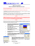
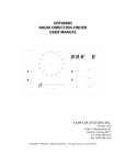
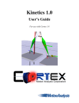
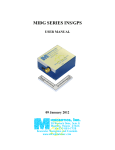
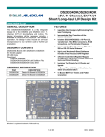
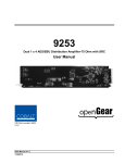
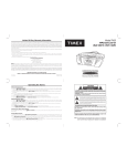
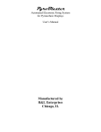
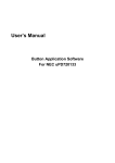
SLC10232
SINGLE-CHANNEL SERIAL
VOLTAGE LEVEL CONVERTER
USER MANUAL
(October 2008)
icrobotics, Inc.
28 Research Drive, Suite G
Hampton, Virginia 23666
+1-757-865-7728
Innovative Navigation and Controls
www.microboticsinc.com
1 Introduction. The Microbotics SLC10232 is a single-channel full-duplex serial voltage converter supporting RS-232 Ù RS-422
and RS-232 Ù TTL voltage level conversions. The board’s small size allows it to be mounted directly in the user wiring harness,
and the SLC10232 can be powered by any convenient DC source of 4 to 40 VDC, thus reducing the real estate needed to effect these
voltage level conversions. Each board has an RS-232 receiver connected to an RS-422 output driver, and an RS-422 receiver
connected to an RS-232 output driver. Each receiver-driver set is independent except for common ground and power connections.
A 1.65V reference is provided by the SLC10232 in order to bias the RS-422 receiver in order to operate the RS-422 receiver as a
TTL-level receiver. NOTE THAT THE SLC10232 IS STRICTLY A VOLTAGE LEVEL CONVERTER – THE BOARD DOES
NOT PERFORM ANY DATA RECLOCKING OR DATA FORMAT CONVERSIONS.
1.30 [33.02]
1.10 [27.94]
.10 [2.54]
.15 [3.86]
.30 [7.62]
.075 x 45 DEG
4 PLCS
.096 [2.44] DIA
2 PLCS
Figure 1. SLC10232 Physical Dimensions.
2 Wiring the SLC10232 to the User System. Connections to the SLC10232 are normally made via direct wiring to the holes on
the board. Extreme care should be taken when soldering to the board to prevent damage to the pads or adjacent components.
The RS-422 signals are grouped at one end of the board (Figure 2), while the RS-232 signals are grouped at the other end (Figure 3).
Power input and return lines are available at both groups of signals. The signal pads for the SLC10232 are:
VIN
GND
RA
RB
TA
TB
RXD
TXD
COM
VR
Board Power (4V to 40V Input) (Two pads provided)
Power Ground (negative side) (Two pads provided)
RS-422 negative data receipt into SLC10232 (MARK Low) – data passed to TXD
RS-422 positive data receipt into SLC10232 (MARK High) – data passed to TXD
RS-422 negative data transmit from SLC10232 (MARK Low) – data passed from RXD
RS-422 positive data transmit from SLC10232 (MARK High) – data passed from RXD
RS-232 data receipt into SLC10232 (MARK negative) – data passed to TA/TB
RS-232 data transmit from SLC10232 (MARK negative) – data passed from RA/RB
Ground returns for the RS-422 and RS-232 signals – Tie to Ground of User RS-232 and RS-422 Ports (Two pads provided)
Voltage supplied by SLC10232 when needed to bias RA for TTL-level receipts
Figure 2. RS-232 Signals.
Figure 3. RS-422 Signals.
SLC10232 SINGLE-CHANNEL SERIAL VOLTAGE LEVEL CONVERTER USER MANUAL
1
2.1 Power Connections. Any voltage between 4VDC and 40VDC may be used to power the SLC10232. The positive side of the
power source is connected to either of the VIN pads, while the negative side of the power source is connected to either of the GND
pads. While all GND and COM signals are electrically connected to the board Ground, the COM lines are not designed nor sized for
returning the power supply current. DO NOT USE THE COM LINES FOR POWER RETURN.
There are two pads each for VIN and GND, one set near the RS-232 signal pads, and one set near the RS-422 signal pads. Either pad
may be used for its associated power connection. The VIN and GND pad pairs can also be used to pass power from one side of the
board to the other in order to improve cable wiring (this would eliminate one pair of wires in the cable). If the VIN and GND pad pairs
are used to pass power through the board, the current must be limited to less than 100 milliamps. FAILURE TO LIMIT THE
CURRENT TO LESS THAN 100 MILLIAMPS WHEN USING THE SLC10232 TO PASS THE POWER RAILS (VIN AND GND)
MAY CAUSE ELECTRICAL FAILURE OF THE SLC10232 BOARD AND VOIDS THE BOARD WARRANTY.
2.2 RS-232 Connections. Three signal lines are used for RS-232 connections (Figure 2). The RXD line is the RS-232 signal
received by the SLC10232 from the user system, which is then passed to the TA and TB outputs. The TXD line is the RS-232 signal
transmitted by the SLC10232 to the user system, having been passed from the RA and RB inputs. The COM line is a signal Ground
return for the RS-232 signals, and must be connected to the Ground of the user RS-232 Port. Figure 4 shows a typical connection
for the RS-232 signals, while Figure 5 shows a typical connection to a user PC. FAILURE TO CONNECT THE COM LINE TO
THE USER PORT GROUND MAY CAUSE ELECTRICAL FAILURE OF THE SLC10232 AND VOIDS THE BOARD
WARRANTY.
POWER IN
(POSITIVE, 4-40 VDC)
VIN
POWER RETURN
(NEGATIVE, GROUND)
SLC10232
R b/Rpos /R+
TA
R a/Rneg /R-
RXD
DATA
IN
TXD
RB
COM
RA
COM
USER RS-232
SYSTEM
R4
120 Ω TERMINATION
(IF REQUIRED)
USER RS-422 SYSTEM
TB
DATA
OUT
GND
USER RECEIVER
120 Ω TERMINATION
(IF REQUIRED)
GND
TWISTED PAIR
DATA
IN
Tb/Tpos /T+
DATA
OUT
Ta/Tneg /T-
TWISTED PAIR
GND
Figure 4. Typical User Connections to the SLC10232 Board.
POWER RETURN
POWER IN
(POSITIVE, 4-40 VDC) (NEGATIVE, GROUND)
VIN
GND
USER RS-422 SYSTEM
Tb
RB
Ta
RA
Rb
TB
RXD
Ra
GND
TA
COM
COM
TO USER PC
TXD
SLC10232
2
DATA
IN
3
DATA
OUT
5
GND
DE9S
(FEMALE CONNECTOR)
Figure 5. Using the SLC10232 to Interface a PC to an RS-422 System.
2
SLC10232 SINGLE-CHANNEL SERIAL VOLTAGE LEVEL CONVERTER USER MANUAL
2.3 RS-422 Connections. Five signal lines are used for RS-422 connections (Figure 3). The TA and TB pair is the differential
signal transmitted from the SLC10232 to the user system, having been passed from the RXD input. The RA and RB pair is the
differential signal received by the SLC10232 from the user system, which is then passed to the TXD output. Note that, in both
transmitter and receiver signals, the ‘A’ references the negative signals, while the ‘B’ references the positive signal. The COM line is
a signal Ground return for the RS-422 signals, and must be connected to the Ground of the user RS-422 port. Figure 4 shows a
typical connection for the RS-422 signals. FAILURE TO CONNECT THE COM LINE TO THE USER PORT GROUND MAY
CAUSE ELECTRICAL FAILURE OF THE SLC10232 AND VOIDS THE BOARD WARRANTY.
RS-422 differential transmissions, when using twisted pair cabling, drastically reduces electrical noise generated by the transmitted
signals while rejecting electrical noise induced into the receiving signals. When data rates are high or the cable lengths are long,
signal reflection can become an issue in transmissions. In these cases, a 120Ω termination resistor is placed across the twisted pair
lines as close to the RS-422 receiver as possible. The SLC10232 board provides a location for installing a 0402-sized termination
resistor across the RA and RB lines (Figure 6).
Figure 6. Location of On-Board Receive Line Termination Resistor.
2.4 TTL-Level Connections Using the RS-422 Port. The RS-422 Port of the SLC10232 may be used to interface TTL-level
signals, effectively creating a TTL Ù RS-232 converter (Figure 7). In this case the TB signal is used as the TTL-level output to the
user system, while the TA signal is unused. The RB signal is used to receive the TTL-Level signal from the user system (note that, in
this case, the default state of the RB signal with no input is ‘LOW’). To force the RS-422 receiver to “see” the TTL-level signal at the
RB input as a differential signal, the RA input must be biased by connecting it to the on-board 1.65V VR output.
SLC10232
TB
DATA
IN
TA
RB
DATA
OUT
RA
USER TTL SYSTEM
VR
COM
GND
Figure 7. Using the RS-422 Port for TTL-Level Signals.
SLC10232 SINGLE-CHANNEL SERIAL VOLTAGE LEVEL CONVERTER USER MANUAL
3
4
SLC10232 SINGLE-CHANNEL SERIAL VOLTAGE LEVEL CONVERTER USER MANUAL
GENERAL SPECIFICATIONS, SLC10232
(August 2008)
All specifications subject to change without notice
Max
Typ
Power
Input Voltage
Input Current
40
4.5
3
Signal Rate
Baud Rate
250
RS-422 Signals
Differential Driver Output (No Termination)
Differential Driver Output (120Ω Termination)
Receiver Input Voltage
Receiver Differential Threshold
Receiver Input Hysteresis
Input Resistance
TTL-Level Conversions
VR Out (Connected to RA)
VIH (RB)
VIL (RB)
VOH (TB)
VOL (TB)
IOH (TB)
IOL (TB)
Environment
Operating Temperature
Storage Temperature
Vibration
Shock
4
V
ma
DC
KBaud
3.3
2.0
-7.0
-200
12.0
200
50
12
1.65
5.5
.8
3.3
.4
8
-8
RS-232 Signals
Input Range
Input Threshold High
Input Threshold Low
Input Hysteresis
Input Resistance
Output Voltage Swing
Physical
Size
Weight
Min
25
2.4
7
2.0
0
2.0
0
-25
1.5
1.2
.5
5
±5.4
.6
3
±3.7
1.3” [33.02 mm] L x .3” [7.62 mm] W x .22” [5.59 mm] T
1.2 g [.042 oz]
-40 to +85 °C
-55 to +125 °C
6 grms
100 g, 8 ms, ½ sine
SLC10232 SINGLE-CHANNEL SERIAL VOLTAGE LEVEL CONVERTER SPECIFICATIONS
V
V
V
mV
mV
KΩ
V
V
V
V
V
ma
ma
V
V
V
V
KΩ
V
Wiring of the MIDG II PC Interface Cable Using the SLC10232.
WARRANTY; DISCLAIMER AND LIMITATION OF REMEDIES: MICROBOTICS WARRANTS ITS PRODUCTS
AGAINST DEFECTS IN MATERIALS AND WORKMANSHIP UNDER NORMAL USAGE FOR A PERIOD OF ONE YEAR
AFTER DELIVERY TO THE END USER. MICROBOTICS MAKES NO ADDITIONAL WARRANTIES WHATSOEVER
WITH RESPECT TO ITS PRODUCTS, EXPRESS OR IMPLIED, INCLUDING WITHOUT LIMITATION, ANY WARRANTY
OF MERCHANTABILITY OR FITNESS FOR ANY PURPOSE, OR AGAINST INFRINGEMENTS OF PATENT OR OTHER
RIGHTS OF THIRD PARTIES IN THE PRODUCTS.
Customer will provide Microbotics the right to inspect any Products which Customer claims do not conform to the
Microbotics Warranty. THE EXCLUSIVE REMEDIES FOR NONCOMPLIANCE WITH ANY MICROBOTICS WARRANTY
SHALL BE, IN MICROBOTICS' SOLE AND ABSOLUTE DISCRETION, EITHER REPAIR OF THE NONCONFORMING
PRODUCTS, REPLACEMENT OF THE NONCONFORMING PRODUCTS, OR RETURN OF SAME FOR REPAYMENT
OF THE PURCHASE PRICE.
MISUSE: Microbotics shall have no liability or obligation to Customer with respect to any of the Products which have been
subject to abuse, misuse, improper use, negligence, accident, modification, alteration, tampering, any use of the Products
outside their normal environment, or any alteration of any literature with respect to the Products.
LIMITATION OF DAMAGES RECOVERABLE BY CUSTOMER: WITHOUT LIMITATION OF ANY OTHER PROVISION
IN THESE TERMS AND CONDITIONS LIMITING OR EXCLUDING LIABILITY OF MICROBOTICS, THE EXCLUSIVE
DAMAGES RECOVERABLE BY CUSTOMER FOR ANY CLAIM OF ANY KIND WHATSOEVER ARISING FROM OR IN
ANY WAY CONNECTED TO THE PRODUCTS, REGARDLESS OF THE LEGAL THEORY, SHALL NOT BE GREATER
THAN THE ACTUAL PURCHASE PRICE OF THE PRODUCTS PAID BY CUSTOMER WITH RESPECT TO WHICH
SUCH CLAIM IS MADE, AND IN NO EVENT SHALL MICROBOTICS BE LIABLE FOR ANY SPECIAL, INDIRECT, OR
INCIDENTAL OR CONSEQUENTIAL DAMAGES OF ANY KIND, INCLUDING WITHOUT LIMITATION ANY DAMAGES
WITH RESPECT TO LOSS OF INCOME, COMPENSATION OR PROSPECTIVE PROFITS, ANY EXPENDITURES,
INVESTMENTS OR COMMITMENTS OF CUSTOMER, ANY LOSS WITH RESPECT TO THE ESTABLISHMENT,
DEVELOPMENT OR MAINTENANCE OF BUSINESS REPUTATION OR GOOD WILL, OR ANY LOSS INCURRED IN
OBTAINING SUBSTITUTE PRODUCTS OR SERVICES, OR ARISING FROM THE CLAIMS OF THIRD PARTIES,
INCLUDING CUSTOMERS.
FORCE MAJEURE: Without limitation of any clause herein limiting or exculpating Microbotics from liability, Microbotics
shall not be responsible or liable for any failure to perform, or any delay in supplying if occasioned in whole or in part by act
of God or the public enemy, fire, explosion, perils of the sea, flood, drought, war, riots, civil insurrection, sabotage, accident,
embargo, governmental priority, requisition or allocation or any action of any governmental authority (or any refusal of such
governmental authority to provide necessary authorization), or shortage or failure of supply, materials, fuel, transportation
or labor, or strikes or other labor trouble, or any occurrence, act, cause or thing beyond the reasonable control of
Microbotics, all of which shall excuse any failure or delay on the part of Microbotics, and Microbotics shall have no
obligation or liability whatsoever arising out of or in connection with any such failure or delay.
POLICY ON RETURNS: In the event of any shortage, damage, defect or discrepancy in or to a shipment of Products,
Customer shall promptly report the same to Microbotics and furnish such written evidence or other documentation as
Microbotics may reasonably require. Except as specifically authorized in the Warranty provisions above, Microbotics shall
not be liable for any such shortage, damage, defect or discrepancy unless Microbotics has received notice and
substantiating evidence thereof from Customer within five (5) days of arrival of the Products. If the substantiating evidence
delivered by Customer demonstrates to Microbotics' reasonable satisfaction that Microbotics is responsible for such
shortage, damage, defect or discrepancy, Microbotics shall deliver additional or substitute Products to Customer in
accordance with the delivery terms otherwise set forth herein; provided, however, that in no event shall Microbotics be
liable for any additional costs, expenses or damages incurred by Customer, directly or indirectly, a result of such shortage,
damage, defect or discrepancy in or to a shipment.
All returns of Products by Customer, for whatever reason, shall be made, at Customer's sole expense, DDP Microbotics'
headquarters office in Hampton, Virginia, USA (INCOTERMS 2000). All sales to Customer are final, and Microbotics will
not accept any returns of Products unless and until prior written authorization is received by Customer from Microbotics.
Microbotics will not accept returns based upon delays in shipment by Microbotics or receipt by Customer or market
conditions (including changes in demand for or popularity of any of the Products).
WARRANTY