1
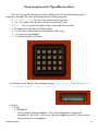
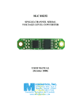
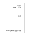
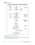
PyroBlaster
Automated Electronic Firing System
for Pyrotechnic Displays
User’s Manual
Manufactured by
R&L Enterprises
Chicago, IL
Congratulations PyroBlaster user:
All of us at R&L Enterprises would like to thank you for choosing the PyroBlaster to
fire your pyrotechnic display. The PyroBlaster is one of the industry’s most advanced
firing controls. Whether you are firing a fully automated show synchronized to a sound track or
choosing your cues and firing them one at a time, PyroBlaster is packed with features that
are sure to satisfy your expectations. After a long day of hard labor in the hot sun,
PyroBlaster puts the fun back in going to a fireworks show by allowing everyone including
the person pushing the button to watch the show because at shoot time there’s only one button
to worry about.
With security in mind, four of PyroBlaster’s six top level menus are password
protected to prevent unauthorized access. These passwords can be changed or even bypassed in
the Security menu or reset to the factory defaults in the Setup menu (a field service password is
required here).
Safety is also one of PyroBlaster’s design goals. The wiring Strips have an
individual relay for each Terminal pair. While the relay is de-energized it provides a safety
shunt for the igniter(s) connected to it and isolation from all other circuits. When the relay is
energized the Terminal pair is disconnected from its safety shunt and connected to the fire
circuit. The fire circuit is driven by an intrinsically safe power supply (about one tenth of the
guaranteed no fire current for most 1A igniters) except during firing. That means there is not
enough energy to fire any connected igniters. This is the current used to verify wiring
continuity. The only way to get enough energy to fire an igniter to the Terminal is to enter a
Fire menu (password required), insert and turn the Operator’s Key to the Armed position and
press the Fire Bush Button.
We also put some thought into ease of use. Most firing systems have a way to verify
wiring continuity and report the results at the control console. When a technician goes out to
remedy a wiring fault at a PyroBlaster Strip, he’ll be greeted by a glowing LED positively
identifying the Terminal with the fault. When the fault is remedied, the LED changes from red
to green. There’s no need to devise some weird hand signals so the console operator can
communicate the current continuity state to the technician trying to repair the fault.
Thanks again,
Dale Smith
Proprietor
R&L Enterprises
Chicago IL 60656-1406
(630) 887-7214
PyroBlaster Manual
2
PyroBlaster system components
All of the PyroBlaster system components are manufactured with heavy duty steel
enclosures and an easy to see safety orange coating that will withstand temperatures of 1000°F.
The control console for the PyroBlaster system called the ‘Head’ is 28 9/16” wide by
7 5/8” high by 15 1/4” deep. It features a sloped front with a 16 character by 2 line Vacuum
Florescent Display, a 20 button Key Pad, a Key Switch and a lighted Push Button. The power
switch and power input connectors are on the right side. On the back are 16 output connectors
and a DE9S connector for RS232 communication with a PC’s COM port. Included with every
Head are a CD with PC software for downloading cue files to the Head, power cord with a 1”
automotive type power plug, external 15V 4A power supply, serial cable and users’ manual.
The optional PyroBlaster ‘Hub’ is 28 9/16” wide by 4 7/8” high by 16 5/8” deep.
There is one input connector on the front that accepts signals from the Head and 16 output
connectors on the back that send signals to the Strips. Shows with more than 256 cues will
require at least one Hub. Up to 16 Hubs may be connected to the Head and up to 16 Strips may
be connected to each Hub to attain the 4096 cue system capability.
Igniter wires connect to the PyroBlaster system at the Strips. The Strips are 12”
wide by 6 17/32” high by 2 7/8” deep. The input connector is on the bottom and there are two
key-hole slots on the back. On the front there are 16 pairs of spring Terminals for connecting
igniter wires. Next to each Terminal pair is a Red/Green LED that indicates the continuity
status during wiring verification.
All these PyroBlaster components interconnect with Cables that R&L Enterprises
manufactures in two standard lengths, 20’ (6 meter) and 100’ (30 meter). Other lengths may be
custom ordered or longer lengths may be reached by daisy-chaining shorter cables.
PyroBlaster Manual
3
Quick start field wiring
The system will need to be powered. This can be done in one of two ways.
The most common way to power the system is to use a FULLY CHARGED 12V
automotive booster battery. This can be any 12V 10AH or larger battery, but it
MUST be fully charged (you wouldn’t want to miss the finale because the battery ran
out). Some operators prefer two batteries, one for use during setup, programming and
continuity check and the other for firing.
A 12-15 Volt 4 Amp AC or DC power supply using utility line power (the system
draws less than 15W in most modes, but may exceed 40W while firing HV cues).
After you have your guns set up, you can mount Strips on the side of the racks with a pair
of screws 6” apart with the heads protruding about ¼”.
There are keyhole slots on the back of the Strips for hanging this way. You can also lay
the Strip on the ground near an array of box items. As you load shells into the guns they can be
wired to the Strips.
PyroBlaster Manual
4
Quick start field wiring continued
There is no need to worry about those safety shunts, each Terminal pair on the
PyroBlaster Strip has a relay that shunts the Terminals and isolates them from all other
circuits. During continuity check and firing one relay at a time connects a Terminal pair to the
fire circuit. The fire circuit is connected to an intrinsically safe power source (about one tenth
of the guaranteed no fire current for most 1A igniters) except during firing.
If you wish to connect more than one igniter to a Terminal pair, they must be wired in
series like in the illustration below. Be sure the splices are twisted tight enough that they will
keep a good electrical connection and then protect them from contact with any other conductive
material. The free ends connect to a Terminal pair on a PyroBlaster Strip. If more than
four igniters are connected to a terminal pair (up to 20 may be connected to one cue) or if more
than ten feet of wire smaller than 18 AWG is used, the firing program should use the high
voltage flag for that cue.
PyroBlaster Manual
5
Quick start field wiring continued
Once all the igniters are connected to a Strip, connect a Cable to its input connector. If
there are no more than 16 Strips in the show, they can connect directly to the Head with 100’ or
longer Cables (Hubs may be used if it simplifies cable routing). Otherwise use a 20’ (or other
convenient length) Cable to a Hub. Finally connect all the Hubs to the Head with 100’ or
longer Cables.
The Cable connections determine the wiring address for each cue. Each cue has a three
letter wiring address using the letters ‘A’ through ‘P’. The connectors on the back of the Head
and Hubs as well as the Terminal pairs on the Strips are labeled ‘A’ through ‘P’. The wiring
address for each cue is the Hub, Strip and Terminal pair (HST) where that cue’s igniter is wired.
Hubs get their single letter address (H) from the letter of the connector on the Head where they
connect. Strips have a two letter (HS) address that is the address of the Hub to which they
connect followed by the letter of the connector on the Hub to which they connect. If a Strip is
connected directly to the Head, its H and S addresses are both the letter of the connector on the
Head where it is connected. The third letter of the wiring address comes from the letter next to
the Terminal pair to which the igniter connects. Wiring addresses must coordinate with the
program that is used to fire the show.
PyroBlaster Manual
6
Quick start programming
The quickest way to create a program in the Head is to ‘learn the field’ after all wiring is
completed. If you use this method, continuity check may not be meaningful because ProgramLearn uses the continuity check algorithm to determine which cues are connected and creates a
program entry for each connection. For this to be successful, you must know how many cue
points were supposed to be wired. If the number of learned cues differs from the number
expected, you may have to audit the generated program to find the missed cue(s). You can use
Program-Edit to add the missed cue(s). The learned program will have equally paced (every
00:01.46) cues starting with address AAA through PPP. If you have Strips connected directly
to the Head, they will have the same Hub and Strip address (AA, BB … OO or PP). You may
want to use Program-Edit to reorder a couple cues. When you exit Program-Edit and Save
Changes the program is automatically sorted by fire time and then stored in the nonvolatile
memory.
Suppose, for example, you have a small show with 240 shells in the open shoot, 3 box
items for the grand-opening, mid-time and pre-finale and 10 chains of shells for the finale. You
would probably want the finale wired to one strip and the boxes to another and connected
directly to the Head and 15 Strips for the open shoot wired to one Hub. Connect the Hub to the
Head between the Strip for the boxes and the Strip for the finale to minimize the editing needed
to reorder the show. The first box will be first in the program, the second and third boxes need
to have their fire times changed. If there is more than 200’ of cable from the Head to the Strip,
more than 10’ of wire less than 18 AWG connecting igniters to the Strip or more than four
igniters on a single cue, those cues should use the high voltage (V) flag.
It’s always a good idea to perform a Continuity-All check before firing your show. If
you created the program with Program-Learn, you would probably want to shoot it with FireStep. This method uses the fire time entries for firing sequence but actual fire timing is
provided by the operator’s actuation of the fire push button.
PyroBlaster Manual
7
Downloading a program from a PC to the PyroBlaster Head
If you wish to create a file on a PC for your show program, there is a utility supplied on
the CD that shipped with the PyroBlaster Head. It is called DownLoad.exe and its function
is to transmit a cue file to a COM port that connects the PC through a 9 pin RS232 serial cable
to the Head.
The cue file that DownLoad expects is a plain text file that can be exported from a
choreography program or created with a text editor like NotePad. Each cue should be on a
separate line and contain the required FireTime and WiringAddress fields and the optional
Flags and comment fields.
The FireTime field takes the form ‘MM:SS.HH’ (Minutes, colon, Seconds, point
Hundredths; important, no spaces or other punctuation) and has a range of values from
‘00:00.00’ to ‘99:59.99’. The WiringAddress field takes the form ‘HST’ (spaces permitted) and
has a range of values from ‘AAA’ to ‘PPP’ (4096 unique values). The optional flags field is
any (all or none) of the characters ‘!’ to fire the cue using High Voltage, ‘~’ to mark this cue as
part of a multiple cue ‘Wave’ effect or ‘|’ to mark the end of the finale when using the reverse
firing method. The FireTime, WiringAddress and Flags fields may appear in any order on the
line, but to aid human readability, you should remain consistent. The comment field should be
last and avoid using any of the flag characters ‘!’, ‘~’, ‘|’ or ‘*’. A comment line that doesn’t
contain any of the other cue fields may use the flag characters ‘!’, ‘~’, ‘|’ or ‘*’ but should avoid
the ‘:’ and ‘.’ characters.
PyroBlaster Manual
8
Downloading a cue script to the PyroBlaster Head continued
Once you have the cue file ready, connect the cable from the PC’s COM port to the serial
port jack on the back of the Head. Turn the Head on and navigate to Program-Download. If the
PC’s CD drive is D: and the PyroBlaster CD is in the drive, open a console box (this is
usually in the Start menu Programs-Accessories-Command Prompt) type ‘D:DownLoad
YourFile.cue COM1’ and press ‘Enter↵’.
PyroBlaster Manual
9
Menu navigation in the PyroBlaster Head
The Key Pad on the front panel of the PyroBlaster Head is used for making menu
selections, entering PIN codes and editing the stored firing program.
• 1, 2, 3, 4, 5, 6, 7, 8, 9 & 0 are used to make menu selections.
• - & + are used to alter the show clock in Automated Firing.
• ↑, ←, → & ↓ are used in Program Edit to select and alter cue data.
• M changes the sort order in Program Edit.
• C is the clear or Back Space key during PIN code entry.
• ↵ is used to accept changes.
• ∅ is used to cancel a selection.
Welcome screen displays the scrolling message 'R&L Enterprises PyroBlaster built
yyyy/mm/dd hh:mm:ss - - - Press "↵" to start. '.
Select:
1. Setup
1.1. Brightness
Select suitable display brightness. The selected brightness is displayed
immediately. Press the ↵ key to save the new brightness, or the ∅ key reverts to
the previously saved brightness.
PyroBlaster Manual
10
PyroBlaster Menus continued
1.1.1. Dim 25% (night)
1.1.2. 50% (sunset)
1.1.3. 75% (overcast or dusk)
1.1.4. Bright 100% (sunlight) (default)
1.2. Dwell Adjust
Select the approximate time that fire current (about1.5A) is applied to the electric
igniter for all HV hits and LV hits in automatic firing mode (LV hits in other
firing modes receive firing current as long as operator’s push button is held).
1.2.0. Min (10mS)
1.2.1. (20mS)
1.2.2. (30mS)
1.2.3. (40mS) (default)
1.2.4. (50mS)
1.2.5. (60mS)
1.2.6. (70mS)
1.2.7. (80mS)
1.2.8. (90mS)
1.2.9. Max (100mS)
1.3. Scroll Speed
Select the speed that Menus and other scrolling messages pass across the screen.
1.3.0. Fastest (20Hz)
1.3.1. (10Hz)
1.3.2. (6.7Hz)
1.3.3. (5Hz)
1.3.4. (4Hz) (default)
1.3.5. (3.3Hz)
1.3.6. (2.9Hz)
1.3.7. (2.5Hz)
1.3.8. (2.2Hz)
1.3.9. Slowest (2Hz)
1.4. Defaults
Enter the Field Service PIN (837367868887868↑). Resets the above settings and
the user PINs to their default values:
Maintenance PIN becomes 11111111
Operator (Fire) PIN becomes 18436572
Programming PIN becomes 13572468
Security PIN becomes 13587654
2. Continuity
PyroBlaster Manual
11
PyroBlaster Menus continued
2.1. All
Scans all HST addresses for continuity and compares to the stored program.
When finished it reports the number of mismatches ‘Done # Faults – pak ’. User
may then advance through the list of faulted HST addresses and view a live
display of the continuity state by pressing any key. The ∅ key exits at any time.
2.2. Strip
Enter the HS address for the strip to test. While testing, displays the Terminal ID
to indicate continuity or ‘–‘ for open at each of the strip’s terminals. The ∅ key
exits, any other key returns to the enter HS address screen.
2.3. Term
Enter the HST address for a terminal pair to test. Like the strip test except only
one point is tested and continuity is reported with the words ‘Open’ or ‘Short’.
3. Program
Enter the Program PIN
3.1. DownLoad
Accepts a program from the software supplied on the CD running on a PC
connected to the serial port on the back of the Head.
3.2. Edit
View and modify the stored firing program. On entry searches the program for
multiple cues with the same HST address. If any duplicates are found, the list is
sorted by HST and the initial view is the first duplicate cue. If no duplicates are
found, the list is sorted by fire time and the initial view is the first cue. The
following keys are recognized.
↵
Search for a cue by fire time or HST address. Uses CueEdit (see below) to
enter the fire time or HST address to find. If both values are entered, HST
address is used as the preferred search. Search by time may fail if the program
is sorted by HST.
∅
Exit Program View / Edit. User is prompted to:
3.2..1. Abandon Changes
Exits without saving changes. Program list reverts to last saved.
3.2..2. Continue Editing
Returns to Program View / Edit to continue editing.
3.2..3. Save Edits
Sorts edited cue list by fire time and saves to EEPROM.
+
Inserts a new cue and calls CueEdit (see below) to enter the fire time, HST
address and VWF flags for the cue.
Deletes the current cue after asking the obligatory ‘are you sure?’ Answers
other than ‘↵’ abort the deletion.
PyroBlaster Manual
12
PyroBlaster Menus continued
C
Change the current cue data (CueEdit). Recognizes these keys:
↵
Accept changes and exit.
∅
Abandon changes and exit. Passes canceled flag back to caller.
+ or ↑
Increments the value under the cursor. Units digit of two digit fields carry to
tens digit. Does not roll past maximum value for the field.
- or ↓
Decrements the value under the cursor. Units digit of two digit fields
borrow to tens digit. Does not roll past minimum value for the field.
←
Moves the cursor to the left. Wraps from the left edge to the right. Skips
over field delimiters.
→
Moves the cursor to the right. Wraps from the right edge to the left. Skips
over field delimiters.
↓
View the next cue in the list.
M
Toggle the sort order for the cue list between fire time and HST address.
↑
View the previous cue in the list.
3.3. Learn
Creates a new cue list by examining the field and making an entry for every HST
address where continuity is found. Fire time values start at 00:00.00 and
increment by 00:01.46 for each cue.
4. Fire
Enter the Operator (Fire) PIN. Operator’s key must be turned to the armed position to
continue. The ∅ key returns to the main menu.
4.1. Automated
Shoot the program using the timing specified in the stored cue list. The ∅ key
aborts back to the main menu, any other key starts the show clock. The operator’s
key must remain in the armed position and the operator’s push button must remain
pressed for the duration of the show. If the push button is released or the key is
turned to the safe position, firing will cease but the show clock continues until the
key and push button are returned to the operating positions. Firing will resume as
fast as possible until it catches up to the show clock. While firing the show clock
may be adjusted with the following keys:
PyroBlaster Manual
13
PyroBlaster Menus continued
+
Advances the show clock 60mS for each press or while held clock runs 60%
fast (160% of normal).
Retards the show clock 40mS for each press or while held clock runs 40% slow
(60% of normal).
4.2. Step
Shoot the program using the sequence specified in the stored cue list. For each
press of the operator’s push button one cue is fired. All consecutive cues with the
wave flag set will be shot with one press of the operator’s push button using the
relative timing specified in their fire time fields. The ∅ key aborts. The show
clock measures the elapsed time from the first shot until the cue list is exhausted.
4.3. Reverse
Shoot the program using the sequence specified in the stored cue list in reverse
order. For each press of the operator’s push button one cue is fired. The Wave
flag is ignored. Shooting stops when a cue with the Fence flag is encountered.
The ∅ key aborts.
4.4. Point
Enter the HST address to fire and V flag for HV/LV. Use push button to fire. The
∅ key returns to enter HST screen. The ∅ key at enter HST screen exits.
5. Maintenance
Enter the Maintenance PIN.
5.1 Fire Relay
Displays the condition of the Fire Relay; ‘like new’ if more than 65,000 cycles
remain, ‘# cycles remaining’ when less than 65,000 cycles remain or ‘Fire Relay
needs replacement soon’ if useful service life has expired. Press Any Key to bring
up Replace Relay menu (except like new condition).
5.1.1 Later
Continue using the installed relay (service life continues to count down from
present value.
5.1.2 New 2 Pole
A new 2 pole relay (recommended) has just been installed; resets service life
to 500,000 cycles.
5.1.3 New 4 Pole
A new 4 pole relay (approved alternate) has just been installed; resets
service life to 200,000 cycles.
5.2. Hub Test
Displays the ID for all connected hubs (upper case letter) and strips (lower case
letter) or a ‘-‘ place holder for unconnected ports on the back of the Head. The ∅
key exits.
PyroBlaster Manual
14
PyroBlaster Menus continued
5.3. Strip Test
Enter the HS address of a strip to test. Sequentially scans terminals A through P
on the selected strip repeatedly. If the operator’s key is in the armed position and
the push button is pressed, fire current (LV) is applied to the selected terminals.
Any key returns to enter HS screen. The ∅ key at enter HS screen exits.
5.4. Term Test
Enter the HST address and V flag of the terminal to test. When push button is
pressed (operator’s key must be in the armed position), fire current is applied to
the selected terminals. Any key returns to the enter HST screen. The ∅ key at
enter HST screen exits.
6. Security
Enter the Security PIN.
6.1. Change PIN
All of the change PIN methods ask for the old PIN and then the new PIN twice. If
the old PIN entered doesn’t match the current PIN or if the two new PIN entries
don’t match each other no change is made. PIN codes may use any combination
of the Key Pad buttons except C, ↵ & ∅.
6.1.1. Maintenance
Change the PIN required for accessing the Maintenance menu.
6.1.2. Fire
Change the PIN required for accessing the Fire menu.
6.1.3. Program
Change the PIN required for accessing the Program menu.
6.1.4. Security
Change the PIN required for accessing this Security menu.
PyroBlaster Manual
15
PyroBlaster Advanced Features
All of PyroBlaster’s internal power conversion uses high efficiency switching power
supply technology. Designed to operate in remote locations (where utility power may not be
available) using readily available 12V automotive booster batteries. PyroBlaster can
operate on AC or DC supply of 12V to 15V. A 15V 4A external power supply is provided as
an accessory with the Head and is capable of firing a show where utility power is available.
PyroBlaster can reliably fire up to four igniters through 200’ of control cable using battery
power. To reach longer control cable distances, up to 20 igniters per cue or where smaller than
18 AWG wire is used to extend igniter wiring to the Strips an internal boost converter steps up
firing voltage to 70V. Normally this converter is disabled to conserve power until the operator
enters one of the firing modes and there are cues with the High Voltage flag set. The current in
the fire circuit during firing is limited to less than 4A to insure connector reliability.
PyroBlaster has four firing methods for a variety of applications. The Automated
firing method is usually used with a program created on a PC with a choreography program like
FINALE Fireworks (www.finalefireworks.com/?pid=1002475). The choreography program
exports a cue file in the PyroBlaster format that can be downloaded into the Head. You
may still want to edit the cue file before downloading or after in the Head’s stored program to
add the Voltage (!) flag where necessary. In this method all the timing and addressing
information is in the program and the operator only needs to start the firing at the right time and
hold the button while watching the show. The Step method is usually used on smaller shows
where the program is created in the field by the Program Learn method and minimal editing is
required to reorder the sequence of some cues. In this method the FireTime field is used only to
determine the firing sequence with actual timing determined by the operator’s push of the
button. If you want a couple cues to fire with one push of the button with a definite separation
in time, set the Wave flag (~) on those cues and program their FireTimes to differ by the
desired separation time. The Reverse firing method is handy for sporting events when we want
to salute each home team score and fire any excess with the post game show’s finale. Arrange
the post game show as you would any other show with cues for the scoring salutes after the end
of the finale. Set the Fence flag (|) on the last shot of the finale. At the start of the game select
the Fire Reverse method and push the fire button when the home team scores. After the game
select either Fire Auto or Fire Step to shoot the post game show. Any extra salutes will fire at
the end of the finale. Some times the AHJ may want a test shot fired before the show. The Fire
Point method allows the operator to pick any cue by wiring address and fire it.
PyroBlaster Manual
16