1
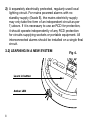
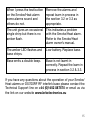
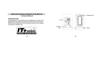
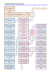
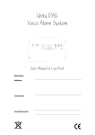
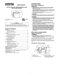
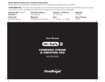
RF INTERLINK BASE
DS700RFF
IMPORTANT: Please read this manual before installation.
If installing the alarm for others please leave a copy for the
end user.
0086-CPD-517190
EN 14604: 2005
CONTENTS
1. Introduction
2. Quick installation guide
3. Installation guide
3.1 DS700RF installation and set-up
3.2 Learning in a new system
3.3 Learning in an additional unit to an
existing DS700RF system
4. Operating conditions
5. Trouble shooting
6. Disposal
7. Limited guarantee
8. Technical specification
2
1. INTRODUCTION
This DS700RF RF interlink base is designed to be used in
conjunction with any BRK mains operated Smoke and Heat
alarms in the 670, 650, 680 series ONLY.
Interlinked Smoke and Heat alarms which utilise RF
interlink technology have the benefit of being able to be
used in a Grade D or E alarm system without the need for
hardwiring connection between each alarm in the system.
This is particularly useful when refurbishing or extending
a property and allows the Grade D or E system to be wired
by way of the un-switched part of a local lighting circuit or
independent circuits at the dwelling’s main distribution board
(ref BS5839 Part 6).
The DS700RF utilises a unique system which provides in excess
of 16 million separate ID codes, one of which is automatically
selected when the system is learnt in on installation. The high
number of alternative codes helps prevent individual systems
in separate properties from interfering with one another and
resulting in unwanted nuisance alarms. Utilising the DS700RF
allows up to 50 alarms to be interlinked in each system.
3
2. QUICK INSTALLATION GUIDE
a) Install each DS700RF base in an appropriate position
at least 300mm from the nearest light fitting (ref Smoke/
Heat alarm instructions) and connect to the nearest mains
circuit. DO NOT SWITCH ON MAINS POWER.
b) Learn in each base by pressing the button (See Fig 1)
using a small screwdriver.
c) Plug in the Smoke and Heat alarms as appropriate onto
each base (See Fig 2). Switch on mains power.
d) Ensure that at least 2 minutes has elapsed before pressing
the test button on each alarm. When the test button on
one of the alarms is pressed all of the other alarms in the
system should sound within 10 seconds.
4
Fig 1.
Fig 2.
Learn in button
5
3. INSTALLATION GUIDE
Please consult the Smoke/Heat alarm owner’s manual for
details of where and where not to site your Smoke and Heat
alarms.
WARNING: Wiring should be installed by a qualified
electrician in accordance with BS7671. Permanent
connection to the fixed wiring of the building should be
made in a suitable junction box. This alarm must not be
exposed to dripping or splashing. Connect the alarm as
late as possible in an installation, particularly in new build,
to avoid contamination. Remove the dust cover before
applying power.
3.1) DS700RF INSTALLATION AND SETUP
Live = Brown
Neutral = Blue
Earth
6
Fig 3.
a) Install the DS700RF docking base on the ceiling no closer
than 300mm from the nearest light fitting. Always refer
to your Smoke/Heat alarm manual for positioning and
installation guidance.
b) Bring wires through either the YT2 trunking knockout on
the side of the base or the knockout in the base itself and
install the wires into the connector terminals marked L
(live), Neutral (N) and Earth (E). See Fig 3.
c) Install ALL bases that will be required in the system in their
appropriate positions.
IMPORTANT: The circuit used to power the alarm must be
a constant 230V AC 50Hz voltage circuit that cannot be
turned off by a switch. BS5839 Part 6 states that:
For mains powered alarms, each with an integral standby
supply (Grade D), the mains electricity supply should take
the form of either:
1) An independent circuit at the dwelling’s main circuit
board, in which case no other electrical equipment should
be connected to this circuit (other than a dedicated
monitoring device installed to indicate failure of the mains
electricity supply to the alarms); or
7
2) A separately electrically protected, regularly used local
lighting circuit. For mains powered alarms with no
standby supply (Grade E), the mains electricity supply
may only take the form of an independent circuit as per
1) above. If it is necessary to use an RCD for protection,
it should operate independently of any RCD protection
for circuits supplying sockets or portable equipment. All
interconnected alarms should be installed on a single final
circuit.
3.2) LEARNING IN A NEW SYSTEM
Learn in button
Amber LED
8
Fig 4.
NOTE: The system must be learnt in before the alarms
are installed on the base.
a) Locate the push button on an installed DS700RF and
press briefly using a small screwdriver (see Fig 1). The
amber LED will illuminate for 3 seconds to indicate that it is
activated. (See Fig 4). The buzzer will also give an audible
‘chirp’ to show that it is working.
b) Repeat this process on every remaining DS700RF required
to be in the system. As each alarm is successfully learnt in
the amber LED will start to flash once every 3 seconds.
NOTE: The DS700RF allows for a period of 15 minutes
during which all bases need to be learnt in.
c) Once all bases are learnt in, install Smoke/Heat alarms
onto each DS700RF as outlined in the owner’s manual
(See Fig 2).
d) Turn on mains power.
e) Ensure all Smoke/Heat alarms in the system display
a green power light and red operating light as per the
Smoke/Heat alarm manual.
9
f) Ensure the amber LED on every DS700RF flashes once
every three seconds.
g) Press the test button on each alarm in the system in turn
and ensure 1) the alarm sounds and 2) it links with every
other alarm in the system.
h) Installation is now complete.
NOTE: If all DS700RF bases have been learnt in before
15 minutes has elapsed, pressing the test button on any
installed Smoke/Heat alarm will cause the learn in
procedure to finish early. This will also test every alarm
in the system. The amber LED on every DS700RF will
flash twice every 3 seconds for a period of 5 minutes after
the learn in process has completed.
If after a period of 15 minutes a unit has failed to learn in, it
will sound a double beep for a period of 5 minutes.
3.3) LEARNING IN AN ADDITIONAL UNIT TO AN EXISTING
DS700RF SYSTEM
If you require an additional alarm to be added to an
existing DS700RF system:
10
a) Following section 3.1, install the new DS700RF in the
required location.
b) Restore mains power to all the installed alarms and the
new DS700RF.
c) Locate the push button on the new DS700RF and press
briefly using a small screwdriver. The amber LED will
illuminate for 3 seconds to indicate it has been activated.
The buzzer will also give an audible ‘chirp’ to show that it
is working.
NOTE: If the existing Smoke/Heat alarms in the property
are mains only powered, it is important that they remain
connected with the mains power on during step (d).
d) Press the test button on one of the alarms in the existing
system long enough to trigger the other alarm(s) in the
system. This should be carried out within 5 minutes.
e) Wait until the amber LED on the new DS700RF flashes
twice every 3 seconds. This indicates that the learn in
process has completed.
f) Before you install the new Smoke/Heat alarm, isolate the
mains power once again.
11
g) Install the new Smoke/Heat alarm onto the DS700RF as
outlined in the alarm owner’s manual (See Fig 2).
h) RESTORE MAINS POWER TO ALL ALARMS. Ensure all
Smoke/Heat alarms in the system display a green power
light and red operating light as per the user’s manuals.
i) Press the test button on the new alarm in the system to
ensure that 1) the alarm sounds and 2) it links with the
existing alarms in the system.
NOTE: The amber LED will stop flashing 5 minutes after
the learn in process has completed. Test (i) should be
carried out regardless of this.
j) Installation is now complete.
NOTE: If after a period 15 minutes the unit has failed to learn
in, it will sound a double beep for a period of 5 minutes.
12
4. OPERATING CONDITIONS
Amber operating LED: Located on the side of the DS700RF,
this LED will remain off during normal working conditions. Any
fault with the DS700RF will be indicated by a flash of the LED
and a single chirp.
Low battery warning: When a low battery condition on the
DS700RF occurs the internal buzzer will chirp along with a
single flash of the amber LED once every minute, for a period
of at least 30 days.
IMPORTANT: The DS700RF has a sealed in battery and
circuitry therefore should you encounter a fault warning
the DS700RF will need to be replaced. As with all work
involving electrical wiring always consult a qualified
electrician.
13
5. TROUBLE SHOOTING
For queries on Smoke/Heat alarm related issues refer to the
specific owner’s manual.
Fault
Action
When I press the learn in
Wait for at least 2 minutes to
button the amber LED on the allow the system to respond.
base does not flash.
If there is no response
within 5 minutes, ensure
unit is correctly positioned.
Attempt to learn in again by
pressing the button.
When I press the test button Ensure all alarms are
on the Smoke/Heat alarm no powered up (green and
other alarms sound.
red LEDS indicating as per
Smoke/Heat alarm owners
manual. Repeat learn in
process in section 3.2 or 3.3
as appropriate.
14
When I press the test button
on the Smoke/Heat alarm
some alarms sound and
others do not.
Remove the alarms and
repeat learn in process in
the section 3.2 or 3.3 as
appropriate.
The unit gives an occasional
single chirp but there is no
amber flash.
This indicates a problem
with the Smoke/Heat alarm.
Refer to the Smoke/Heat
alarm owner’s manual.
The amber LED flashes and
base chirps.
Low battery. Replace base.
Base emits a double beep.
Base is not learnt in
correctly. Repeat the learn in
process in section 3.2 & 3.3.
If you have any questions about the operation of your Smoke/
Heat alarms or DS700RF RF interlink base please contact the
Technical Support line on +44 (0)1452 887570 or email us via
the link on our website www.brkelectronics.eu
15
6. DISPOSAL
This product, the batteries and other accessories
must not be disposed of as unsorted municipal
waste and must be collected separately at the end
of the product’s life. Contact your local authority for
information about collection points in your area.
16
7. LIMITED GUARANTEE
BRK (“the BRK Brands Europe Ltd products”) as distributed by
Sprue Safety Products Ltd (“the Distributor”), are guaranteed
by the Distributor to be free from defects in materials and
workmanship under normal use and service for a period of five
years from the date of purchase.
Neither the Distributor nor BRK Brands Europe Ltd make
any other express guarantees for this product. No agent,
representative, dealer or employee from the Distributor or BRK
Brands Europe Ltd has the authority to increase or alter the
obligations or limitations of the Guarantee. The Distributor’s
obligation of this guarantee shall be limited to the repair or
replacement of any part of the DS700RF base which is found
to be defective in materials or workmanship under normal use
and service during the five year period commencing from date
of purchase. The Distributor shall not be obligated to repair
or replace DS700RF bases which are found to be in need of
repair because of damage, unreasonable use, modifications or
alterations occurring after the date of purchase. This warranty
does not affect a customer’s statutory rights in any way.
17
How to obtain guarantee service
If service is required, return the product to your supplier. The
Distributor makes no guarantee, express or implied, written or
oral, including that of merchantability or fitness for any particular
purpose with respect to battery. In the event of a problem with
your DS700RF base or you have any questions concerning its
use, care and service please consult this manual.
If you require any further help or clarification please write to:
Sprue Safety Products Ltd, Unit 6, Carter Court - Davy
Way, Waterwells Business Park, Quedgeley, Gloucester,
GL2 2DE, United Kingdom or phone our Helpline on:
+44 (0)1452 887 570
www.brkelectronics.eu
Please note that specifications may be subject to change.
18
8. TECHNICAL SPECIFICATION
Power: Independent 10 year (battery for life) lithium cell.
Temperature: (operating):- 0°C - 40°C
Humidity: 0-95% (non condensing)
Warning: Visual and audible low battery warning
Radio Frequency: 868MHz
Wireless Range: Minimum 150m open air
Dimensions: 140mm (D) x 30mm (H)
Approvals: Independently tested and compliant with EMC,
Electrical Safety and Radio Regulations to include requirements
of the R&TTE Directive.
EN300220 v2.3.2 (2010.02)
EN301489-1
EN301489-3
EN50130-4
EN60065
19
Sprue Safety Products Ltd
6 Carter Court, Davy Way
Waterwells Business Park
Gloucester GL2 2DE UK
A Sprue Safety Products Brand
GN1420R3