1
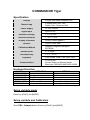
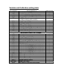
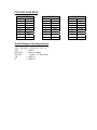
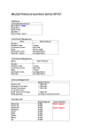
Commandor-Tiger
USER Manual
COMMANDOR Tiger
Specification
Display
Status Lamp
Power Supply
8 Digits Red Seven Segment LED
4 Status Red 3 mm. LED
Stable, Zero, Gross and Net
12 VDC 800mA
Signal Input
Up to 25 mV
Excitation Voltage
5 +/- 0.5 VDC
Internal Resolution
1 / 16,777,216
Display increment
50,000 Levels (Approx.)
Loadcell
Calibration Method
Decimal point
Increment Step
Keyboard
Communication
Up to 6 x 350 Ohm
Software, long-term storage in
EEPROM
0 – 4 Digits
1, 2, 5, 10, 20
Func, Mode, Clear, Tare, Zero, Print
2 x RS-232C
Stream Output or Demand Mode
Baud rate 1200,2400,4800,9600,19200
Keyboard function
KEY
FUNC / SKIP
MODE / ENTER
CLEAR / UP
TARE / DOWN
ZERO / LEFT
PRINT / RIGHT
OPERATION
Setup mode
Setup mode
Clear Tare and Accumulate
Set Tare weight
Set Zero weight
Print in demand mode
SETTING
Skip to next item
Confirm selection
Move up or Increte
Move down or decrete
Move left or skip back
Move right or skip forward
Setup variable mode
Press key [FUNC] and [MODE]
Setup variable and Calibration
Short CAL. Jumper before Press key [FUNC] and [MODE]
Variable and Calibration setting table
FUNCTION
AdR
SER
bAU
PAR
SR2
OUt
RtC
FIL
SPd
FRZ
SAF
bRt
PRN
DESCRIPTION
Set unit address (0-255)
Serial Com:1
Baudrate (1200,2400,4800,9600,19200)
Parity ( 0=8,None,1 1=7,Even,1 )
Serial Com:2
(1=1200,2=2400,3=4800,4=9600)
Output feature (N/A)
Real Time Clock (N/A)
Weight Filter (0-4)
ADC read Speed (0-4)
Weight Freezing (N/A)
Power Safe Mode (0=Disable, 1=Enable)
Display Brightness (0-4)
Print Interlock Weight
DEFAULT
0
3
1200
1
1
0
0
1
4
0
0
3
10
Valid when Short CAL.Jumper
dEC
CAP
StP
AZR
ZER
POZ
StI
GAN
bt1
bt2
bt3
bt4
bt5
bt6
RFP
CAL-0
CAL-1
CAL-2
CAL-3
AdC-dISP
SAVE
Decimal point
Capacity
Division Step (1,2,5,10,20)
Auto Zero Maintennance
% Zero limit ( 0,1,2,5,10 )
Power On Zero (0=Disable, 1=Enable)
Still Weight or Statble level
ADC Gain (0-4)
Lock button No.1 (FUNC) 0=Unlock,1=Lock
Lock button No.2 (MODE) 0=Unlock,1=Lock
Lock button No.3 (CLEAR) 0=Unlock,1=Lock
Lock button No.4 (TARE) 0=Unlock,1=Lock
Lock button No.5 (ZERO) 0=Unlock,1=Lock
Lock button No.6 (PRINT) 0=Unlock,1=Lock
RF Protect feature (Option)
Calibrate Zero
Calibrate Span
Calibrate Zero and Span
Calibrate Manual Setting
Display ADC value
Save setting (Press [ENTER] to save)
0
1000
1
1
10
1
3
1
0
0
0
0
0
0
0
-
CONNECTOR PINS
LOADCELL
1
2
3
4
5
6
7
8
9
Exc+
Sen+
Gnd
SenExcSig+
Sig-
COM:1
1
2
3
4
5
6
7
8
9
Serial Output Stream protocal
STX + WEIGHT + STATUS + CR + LF
STX
= CHR(2)
WEIGHT
= Numeric 8 digits
STATUS
= ‘ ‘:Stable , ‘U’:Movement
CR
= CHR(13)
LF
= CHR(10)
Rx
Tx
Gnd
-
COM:2
1
2
3
4
5
6
7
8
9
Rx
Tx
Gnd
-