1
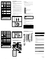
<Specification Comparison Chart> Item Digital input Analog output Q68DAVN Signed 16-bit binary normal resolution mode:-4096 to 4095 high resolution mode:-12288 to 12287,-16384 to 16383 -10 to 0 to 10V DC (External load resistance:2kΩ to 1MΩ) -10 to 10V DC (External load resistance:1kΩ to 1MΩ) Analog Normal resolution mode High resolution mode Digital input Maximum Digital input Maximum output value resolution value resolution range 0 to 5V 1.25mV 0.416mV 0 to 4000 0 to 12000 1 to 5V 1.0mV 0.333mV -10 to 10V 2.5mV -16000 to 16000 0.625mV User range -4000 to 4000 0.75mV -12000 to 12000 0.333mV setting Digital input Analog output value value 2000 10V 1000 5V 0 0V -1000 -5V -2000 -10V I/O characteristics Maximum resolution Overall accuracy Maximum conversion time Absolute maximun output Analog output points Between the output terminal and programmable controller power Insulation supply method Between channels Between external supply power and analog output No. of occupied points Connected terminal block Current consumption External supply power A1S68DAV Signed 16-bit binary -2048~2047 Voltage Current 5mV ±1.0%(±100mV) Ambient temperature 25±5℃:Within ±0.1% (±10mV) Ambient temperature 0 to 55℃:Within ±0.3%(±30mV) Maximum 4 ms/8 channels 80 μs/channel - ±12V 8 channels/module 8 channels/module Photocoupler insulation Photocoupler insulation 5.1 Installation Procedure [1] Secure the MELSEC-Q Series Base Module to the Base Adapter with the supplied attaching 4.1 Handling Instructions (1) Before attempting to install the Unit or carry out the necessary wiring, make certain that the external power supply, used in the system, is shut off on all three phases. Failure to do so may result in electric shock or damage to the product. screws (M4 x 10). (Secure it in four places.) [2] Mount a compatible module under the MELSEC-Q Series onto the MELSEC-Q Series Base Module. (2) Do not touch live terminals. There is a danger of electric shock or malfunction. Also, remove the terminal block installed to the MELSEC-Q Series Module by undoing the terminal (3) Do not modify the Conversion Adapter or take it apart. Doing so will cause failure, malfunction, personal injury, or fire. block attaching screws (one at the top and the other at the bottom). (4) Do not touch the energized part of the Conversion Adapter directly. Contact will cause malfunction or failure in the system. (5) Fasten the Conversion Adapter, and the Fittings securely with retaining screws, and tighten the screws by applying torque within specified limits. Loose screws can lead to the dropping of the converter adapter, or fittings, possibly causing breakage thereof. Excessive tightness of the screws can lead to breakage of the screws, converter adapter, fittings, or MELSEC-Q Series MELSEC-Q Series terminal block attaching screw (Secure it in two places, top and bottom.) Module, possibly causing the dropping, shorting, and malfunction thereof. (6) Use care to prevent foreign materials including cuttings and wiring debris from entering the Conversion Adapter or the MELSEC-Q Series module. These will be cause for fire, failure or malfunction. Non-insulation Non-insulation - Transformer insulation (7) Do not drop the Conversion Adapter, and Fittings, and avoid giving a strong impact to them. Otherwise, breakage will result. (8) If the existing system is installed on a DIN rail, the Base Adaptor is not necessary. The MELSEC-Q 32 points 16 points 20-points terminal block 18-points terminal block 0.65 A 0.38 A - 24V DC +20%,-15% 0.2 A POINT 1. 4. Mounting and Installation A1S68DAV and Q68DAVN differ from each other in the way input/output signals (X, Y) and buffer memory addresses are allocated. Therefore, you need make necessary changes to the sequence program that is used. Series Base Module you use can be mounted onto the DIN rail. screws (M3.5 x 6). (Secure it in two places, top and bottom.) [4] Mount the Conversion Adapter onto the mounting bracket and secure it with the Conversion Adapter attaching screws (M3 x 25). (Secure it in two places, top and bottom.) 4.2 Instructions for Use Item Width dimension of module [3] Secure the mounting bracket to a compatible module under the MELSEC-Q Series with retaining Description Because the module is reduced in width dimension (34.5mm→27.4mm) and thus in area available for wiring, check dimensional data before installing the module. < MELSEC-AnS Series > < MELSEC-Q Series > Precaution Before tightening the installation screws, check that the Conversion Adapter has been securely installed on the MELSEC-Q Series module. Tightening the screws in floating-off state or tilting state will damage the Conversion Adapter installation screws and the mounting bracket. [5] Secure the Base Adapter to the panel with the supplied attaching screws (M5 x 12). (Secure it in four places.) [6] Secure the MELSEC-AnS Series terminal block to the Conversion Adapter with the supplied 27.4 34.5 Depth dimension of module Unit : mm Because the module is increased in depth dimension, check dimensional data before installing the module. attaching screws (M4). [7] Remove the terminal block cover from the MELSEC-AnS Series terminal block and fit the terminal block cover supplied with the Conversion Adapter in place. 5.2 Tightening Torque Tighten the module attaching screws by applying torque listed in the table blow. Application of improper tightening torque will cause dropping, short-circuit, failure, or malfunction. Component attached with screw Base Adapter attaching screw (M5) Q Series module attaching screw (M4) Mounting bracket securing screw (M3.5) Conversion Adaptor attaching screw (M3) MELSEC-AnS Series terminal block attaching screw (M4) 5 Item Digital input Analog output I/O characteristics Maximum resolution Overall accuracy Between external supply power and analog output No. of occupied points Q68DAIN Signed 16-bit binary normal resolution mode:-4096 to 4095 high resolution mode:-12288 to 12287,-16384 to 16383 4 to 20mA DC (External load resistance 0 to 600Ω) 0 to 20mA DC (External load resistance 0 to 600Ω) Digital input Analog output value value 4000 20mA 2000 12mA 0 4mA 4μA Description The terminal block cover for MELSEC-AnS Series is bigger than the width of the MELSEC-Q Series Module. Therefore, it is necessary to replace it with the terminal block cover supplied with the converter adapter. 6. Dimensional Outline Drawing Product Warranty Details Please confirm the following product warranty details prior to product use. Gratis Warranty Terms and Gratis Warranty Range If any fault or defect (hereinafter referred to as “Failure”) attributable to Mitsubishi Electric Engineering Company Limited (hereinafter referred to as “MEE”) should occur within the gratis warranty period, MEE shall repair the product free of charge via the distributor from whom you made your purchase. Ambient temperature 25±5℃:Within ±0.1%(±20μA) Ambient temperature 0 to 55℃:Within ±0.3%(±60μA) Maximum 4 ms/8 channels 80 μs/channel - 21mA 8 channels/module 8 channels/module 4.3 Installation Environment Photocoupler insulation Photocoupler insulation Non-insulation Non-insulation - Transformer insulation 16 points 18-points terminal block 0.85 A 0.38 A Voltage - 24V DC +20%,-15% Current - 0.27A Gratis Warranty Period The gratis warranty period of this product shall be one (1) year from the date of purchase or delivery to the designated place. Note that after manufacture and shipment from MEE, the maximum distribution period shall be six (6) months, and the gratis warranty period after manufacturing shall be limited to eighteen (18) months. In addition, the gratis warranty period for repaired products shall not exceed the gratis warranty period established prior to repair. For detail information, see the user's manual furnished with the MELSEC-Q Series CPU module you use. 32 points Current consumption Item Terminal block cover 9 Analog Normal resolution mode High resolution mode Digital input Maximum Digital input Maximum output value resolution value resolution range 0 to 20mA 5μA 1.66μA 0 to 4000 0 to 12000 4 to 20mA 4μA 1.33μA User range -4000 to 4000 1.5μA -12000 to 12000 0.83μA setting 20-points terminal block Connected terminal block External supply power A1S68DAI Signed 16-bit binary 0~4096 ±1.0%(±200μA) Maximum conversion time Absolute maximun output Analog output points Between the output terminal and programmable Insulation controller power method Between channels 7 Range of tightening torque 2.75 to 3.63N·m 1.39 to 1.89N·m 0.68 to 0.92N·m 0.43 to 0.57N·m 0.78 to 1.18N·m 5. Part Names and Installation Procedure Gratis Warranty Range The gratis warranty range shall be limited to normal use based on the usage conditions, methods and environment, etc., defined by the terms and precautions, etc., given in the instruction manual, user’s manual and caution labels on the product. Warranty Period after Discontinuation of Production POINT 1. (1) A1S68DAI and Q68DAIN differ from each other in the way input/output signals (X, Y) and buffer memory addresses are allocated. Therefore, you need make necessary changes to the sequence program that is used. (2) MEE shall offer product repair services (fee applied) for seven (7) years after production of the product has been discontinued. Discontinuation of production shall be reported via distributors. Product supply (including spare parts) is not possible after production has been discontinued. Exclusion of Opportunity Loss and Secondary Loss from Warranty Liability Regardless of the gratis warranty period, MEE shall not be liable for compensation for damages arising from causes not attributable to MEE, opportunity losses or lost profits incurred by the user due to Failures of MEE products, damages or secondary damages arising from special circumstances, whether foreseen or unforeseen by MEE, compensation for accidents, compensation for damages to products other than MEE products, or compensation for other work carried out by the user. If the existing system is installed on a DIN rail, the Base Adaptor is not necessary. The MELSEC-Q Series Base Module you use can be mounted onto the DIN rail. Take note that a DIN rail installation adaptor made by Mitsubishi is required to mount MELSEC-Q Series Base Module onto a DIN rail. The separately-sold Conversion Adapter DIN rail Mounting Bracket (ERNT-ASQDIN□□) is required to use the Conversion Adapter with a fixture on this Base module. Changes in Product Specifications The specifications given in the catalogs, manuals and technical documents are subject to change without notice. This document is a new publication, effective September 2014. Specifications are subject to change without notice. Developed September 2014 50CM-D180090-C 6 8 10