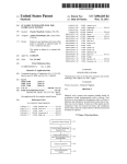
Download Graphical user interface system for steam turbine operating conditions
Transcript
USOO5838588A
Ulllted States Patent [19]
[11] Patent Number:
Sant0s0 et al.
[45]
[54]
GRAPHICAL USER INTERFACE SYSTEM
FOR STEAM TURBINE OPERATING
Date of Patent:
Nov. 17, 1998
5,479,358 12/1995 Shimoda et al. ...................... .. 364/492
5,640,176
6/1997 Mundt et al. ......................... .. 345/146
CONDITIONS
[75]
5,838,588
FOREIGN PATENT DOCUMENTS
Inventors: Nugroho IWan Santoso, Cranbury,
0 389 132 of 0000
N.J.; Walter Zorner, Baiersdorf,
Germany
European Pat. Off. .
OTHER PUBLICATIONS
Patent Abstracts of Japan, vol. 004, No. 072 (M—013), 27
[73] Assignee: Siemens Corporate Research, Inc.,
Princeton, NJ[21]
May 1980 & JP 55 035112 (Toshiba)
“Comparing Display Integration Strategies for Control of a
Simple Steam Plant”, Edlund et al., 2 Oct. 1994, Proceed
ings of the Int’l Conference on Systems, Man and Cyber
Appl. No.: 768,047
_
[22] Flled:
netics, San Antonio, pp. 2686—2691.
Dec‘ 13’ 1996
Omega Engineering Inc., The Data Acquisition Systems,
[51]
Int. Cl.6 ................................................... .. G05B 15/00
vol- 29,11 B—1 to b—18, 1995-_
[52]
US. Cl. .............................. .. 304/528.22; 364/468.03,
“Turbme Back Pressure Idenn?canon And OPtlmlZatlOn
36 4/46801; 36 452825
With Learning Neural Networks”, Mathur et al. Advances in
[58]
Field Of Search ............................. .. 364/557, 468.03,
Instrumentation And Control’ VOL 45’ NO' Pa“ 01’ 1 Jan'
364/46804, 468.01, 528.22, 528.25; 345/145,
146, 340, 428, 915, 919, 920, 921, 970,
_
_
_
_
1990’ PP' 229_236~
Primary Examiner—Louis M. Arana
339
Assistant Examiner—Hien Vo
Attorney, Agent, or Firm—Adel A. Ahmed
[56]
References Cited
[57]
ABSTRACT
U.S. PATENT DOCUMENTS
_
3,873,817
A graphical user interface provides a real-time information
3/1975 Llang .................................... .. 364/492
display for a Supervising engineer in Charge of turbine
4,576,007
272932; 8128881111;
3/1986 Arakawa 61 al...................
.......................
.;;-.23;;a7121
.. 60/660
C°mb1na_“9nS
so of Operatmg Commons are readlly_obser‘_’ed
476797399
7/1987
477647025
8/1988 Jensen _____ __
Smolder _ _ _ _ _ _ _ _
4,827,429 5/1989 silvestri, Jr,
4,891,948 1/1990 Kure-Jensen et al.
4,970,670 11/1990 Twerdochlib
572677435 12/1993 Frenkel et al
573057230
4/1994 Matsumoto et a1‘
5’333’240
7/1994 Matsumoto et i'?j'"
_ _ _ _ __ 60/646
and deviations are made apparent so'that correctlve actlon
374/144
can be lnltlated rapldly. An overvleW of the operatlng
364/494
60/645
364/571-03
60/204
364/495
situation is made more readily apparent by representing the
operating expansion and compression processes by lines on
a Mollier enthalpy/entropy chart. In combination, real-time
parameter values and parameter trends are also presented.
Using the Mollier chart information in conjunction With
395/23
can more qulckly ldentlfy and correct undeslrable and
5:161;
trend and real-time ‘information, the supervising engineer
5,353,628 10/1994 Bellows .......... ..
73/2501
5,386,689
2/1995 BoZich et al.
5,439,160
8/1995 Marcantonio ......................... .. 228/102
Potentially troublesome Operation Conditions
.. 60/39.33
ACRUISIIIUN LEVEL
8 Claims, 14 Drawing Sheets
MEASURED SIGNALS
I
l l l SIMAIIC 55 l
I
CUMMUNICAIIDN LEVEL ‘
EIHERNEI
DMNI~SERVER, REC/let PHASE V
ADMINISIRAIIVE
LEVEL
IELEGRAN
DISIRIBUIUR
TIME’
CONTROL
DELUG
IELEGRAR
RECEIVER
RRTS
RERUIREMENI IELEBRAR
WATCH
DOG
RDIS
RAN DATA TELEBRAM
ACTION
PRUDESS DDNIRUL MANAGER
i
F " *"n.
'i" 7
F
TRAINING ‘
Lung/110m P“?
ESTIMATOR 1 RESULT
PARAMETERS bid
DATA
SCHEME ;
L "i113
FITTED‘
‘FREE’?
DATA 2"‘? MODEL 1
RA N N6 1
5
1 RA R MA
% m
.ELEVEL
PRESENTATION 1 ‘—‘
l
]
FREE
GRAPHICS
RINDABE GUI
A I
L ...... "3
SHARED
MENURV
U.S. Patent
Nov. 17,1998
Sheet 2 0f 14
5,838,588
FIG. 2A
!____________________________
i
Pms—+O
Tms—+O
LAYER (3]
INPUT
CONNECTIONS
I
OUTPUT
CONNECTIONS O-T-v-Tblads
OF
HIDDEN
UNITS
FIG. 2B
3
.L
E.CMA_
_
_
NP
_
_PC
_
C
_N
.I.NPD.mB. 5SX
1w
1r.--I
0
A.
tDm_
!\ SN
m_
mH ETIU
_IN _TI _?u
NE UT
_
S
E1UV. OMD_NHE0ID_
C
ML_
C MA_N
H0E'UL0N
TCTl-I WIMN“
__
UATEL PT10
_
_
ITi3l]:1.
.D 1 AU
MCAALTICHUELMAATTI IOMNL2 Tl~
a E
_
m
1
|_
_l
.I
n
0
U.S. Patent
Nov. 17,1998
Sheet 3 0f 14
FI G . 3
HATER/STEAM CYCLE
EXPEBEENTAL
ANALYSIS
PROGRAM:
GENERATE DATA
/
COMBINE DATA
I
REFDRMAT AND ORGA
NIZE TRAINING AND
TESTING DATAFILE
I
ANN MODULE
TRAINING AND
VALIDATIDN
MDDIFY TRAINING
ANN STRUCTURE
PARAMETERS OR THE
CONVERSE
9
SATISFACTORILY.
I
ANN MDDULE
TESTING
SATISFACTORY?
5,838,588
U.S. Patent
Nov. 17,1998
Sheet 4 0f 14
5,838,588
FIG. 4A
MAIN MENU
FRONT PAGE
MOLLIER
TREND
TURBINE IMAGE
SHARED MEMORY MANAGEMENT
FREE GRAPHICS
L """" "I """" "J
I
SHARED MEMORY
DATA SERVER
DATA BASE
FIG. 4B
FRONT PAGE
HP
PARAMETER LABELS
LP1
LP2
HP DRAWING ROUTINE
T
SIMILAR STRUCTURE
FOR LP1, LP2, . . .
~-—+ -----------------------------
!i_________________.__________________________-_____
GLOBAL LABELS
SHARED MEMORY MANAGEMENT}
U.S. Patent
Nov. 17,1998
Sheet 5 0f 14
5,838,588
FI 6 . 4C
MOLLIER DIAGRAM
HP
LPI
LRRNT'
/\
MDLLIER GRAPH
SIMILAR STRUCTURE
A
FDR LPI, LPE, . . .
PARAMETER LABELS
BACKGROUND
ROUTINE
DATA
DRAWING
l ROUTINE
!L.__._.___._..______________________.__.__________.___.__.
GLOBAL LABELS
GRAPH DATA
SHARED MEMDRY MANAGEMENTJ!
|
FIG. 40
TREND DIAGRAM
HP
LPA
PARAMETER LABELS
LP2
TREND GRAPH
/\
DATA
T_
_
_
_
_
_
_
_ _
i GLOBAL LABELS
-
_
_
_
_
__
I‘
SIMILAR STRUCTURE
FDR LPI, LP2, . . .
DRAWING
ROUTINE
._.—.....__-___._____—.__.—___________.lI
GRAPH DATA
i
SHARED MEMORY MANAGEMENT :
|_ ____________________________________ ___1
U.S. Patent
H5
$2
NH
“8
Mom
2.;
2
@53m20:2
m5
mEI SZ
#31:GE ;
mzE m
5m5 :25
Nov. 17,1998
Sheet 6 0f 14
5,838,588
U.S. Patent
Nov. 17,1998
Sheet 8 0f 14
FIG. 50
Pin=410.30bar
Peh=160.58r‘p|||
Teh 403.06bar
5,838,588
U.S. Patent
5EFIG.
Nov. 17,1998
Sheet 9 0f 14
5,838,588
U.S. Patent
H¢¢
UMQ
m“
we
00
@@
mam“
Nov. 17,1998
Sheet 14 0f 14
5,838,588
m1op4Hzmc
wofp3&2mamE_8&208ogm1.w0za2%é
@mz:
..802
mg?
m
5%
a:
we:
Hi
mzH mnH
£25m.Wo0Os2?
n..os
as"
.02
‘02
‘[02
“o2
.52
H02
womm"
.lomm
m
1%
“am0
.ém
g
isan
8%E $2..0%-3‘-5‘0%. ©“Ham OHam
“
“am
5%
O
“8m
“
6%“OW02
.103
.52
“2m
“am
ém
“
M
w
E
z
a
Q
Z
s
E
@
w
“
5
e
ém
5%
Ham
1
;
n~05~03MOEHOEEO é“_5am .532u5:we:We:5&2
0was?as-02_
m
‘.3
.2
é
é"é“a
“a
"
.lcw
wow
" mom
_
4
325E5a:
5,838,588
1
2
GRAPHICAL USER INTERFACE SYSTEM
FOR STEAM TURBINE OPERATING
CONDITIONS
In a accordance With another aspect of the invention, a
hybrid approach, 5 measured values are utiliZed. Asubset of,
for example, 4 parameter values is used for training the ANN
and another subset of, for example, 3 values is used for
performing a calculation for another intermediate parameter.
Using the intermediate parameter and one of the 5 measured
values, a blade temperature is calculated.
In accordance With still another aspect of the invention,
In the operation of steam turbines, as for turbo
generators, it is important that operating parameters be kept
Within de?ned limits for proper and safe operation, includ
ing start-up and shut-doWn phases. Unsafe operation can
have grave consequences for personal injury and material
damage.
the user interface provides a real-time information display
10
Reference is hereby made to an application by the
present inventors being ?led concurrently hereWith and
for a supervising engineer in charge of turbine operation so
that critical parameter values and undesirable combinations
of operating conditions are readily observed and deviations
entitledAMETHOD FOR BLADE TEMPERATURE ESTI
are made apparent so that corrective action can be initiated
MATION IN A STEAM TURBINE (Ser. No. 08/764,381)
rapidly. While graph plots of parameters can be readily
presented, such a format generally does not readily provide
Whereof the disclosure is incorporated herein to the extent it
does not con?ict With the present application.
15
an overall picture of the state of the turbine With regard to
the distribution and combination of temperature, pressure,
Typically, in steam turbo-generator operations, the tur
bine Was operated around full poWer or, When the demand
for poWer Was insuf?cient, it Was shut doWn. Particularly in
steam Wetness or superheat, and turbulence effects.
operation as part of a large poWer grid, operation at less than
full load may be required. Under such conditions, complex
patterns of temperature, pressure, steam Wetness, reheating,
the operating situation is made more readily apparent by
expansion and compression, may occur, possibly resulting in
combination, real-time parameter values and parameter
In accordance With the present invention, an overvieW of
representing the operating expansion and compression pro
cesses by lines on a Mollier enthalpy/entropy chart. In
excessive turbine blade temperature. Such conditions may
spell blade failure With possibly disastrous consequences.
Thus, monitoring operation under conditions Where the
25
trends are also presented. Using the Mollier chart informa
tion in conjunction With trend and real-time information, the
supervising engineer can more quickly identify and correct
intake steam pressure is at or loWer than the output pressure
undesirable and potentially troublesome operation condi
are of practical importance. Background material is avail
tions.
In accordance With an aspect of the present invention, a
able in books such as W. W. Bathie, “Fundamentals of gas
turbines”, John Wiley and Sons, 1996; and H. Herlock,
“Axial ?oW turbines: Fluid mechanics and
system utiliZes a hybrid ANN (arti?cial neural network)
algorithmic based scheme for estimating the blade tempera
thermodynamics”, ButterWorth, London, 1960.
ture from other measurements Which are commonly avail
Good mathematical models for simulating the steam
able. The commonly available measurement values are
herein utiliZed. The training data for the ANN includes both
behavior in a turbine in its entire operating domain are not
readily available, especially concerning periods in Which the
35
ing detailed description in conjunction With the draWing, in
pressure. During such periods, the ?uid ?oW behavior is
very complex because the radial component of velocity
become signi?cant as compared With the axial velocity
component. The available simpli?ed mathematical models
for simulating the steam behavior during normal loading
typically do not perform properly When the intake pressure
Which
FIG. 1 shoWs a Windage module architecture in accor
dance With the invention;
FIG. 2 shoWs an arti?cial neural netWork based scheme
for blade temperature estimation in accordance With the
invention;
is near or loWer than the output pressure.
In neW large steam turbines, temperature measuring
devices are installed at the respective stages of the HP and
LP casings. These measurements provides an indication to
45
applicable in conjunction With the invention; and
FIG. 5a to 5j shoWs graphical interface vieWs applicable
blade temperature exceeds its limit. The need for blade
temperature monitoring for smaller and older turbine, as
in conjunction With the invention.
During the operation of the steam turbine, heating due to
Windage must be maintained Within alloWable limits by the
operating mode. The Windage modules for HP and LP
turbines in accordance With the present invention Will pro
Well as a more practical and cost effective Ways than
installing temperature probes, has led to a need, herein
recogniZed, for a practical system for estimating in real time
and monitoring turbine blade temperature during operation.
55
In accordance With an aspect of the invention, a method
for blade temperature estimation in a steam turbine utiliZes
deduced from the estimation and other available measure
ment values.
input and output stages. Initially, blade temperature is simu
In the folloWing, examples of the Windage phenomenon
lated by using a Water/steam cycle analysis program as Well
as by directed experiments. An arti?cial neural netWork
(ANN) is trained by presenting the measurement values and
the blade temp values. In a present exemplary embodiment,
method the ANN is used directly to derive operating blade
temp values.
vide the operator With an estimation of the blade temperature
at the respective turbine stages. The interactive user inter
face herein disclosed displays the real-time value, a trend
graph of these values, and the respective states Within the
Mollier diagram. Supervisory recommendation may be
measurement values including pressure and temperature at
locations other than directly at the blades, principally at the
it is found that 4 values provide a satisfactory result. In one
FIG. 3 shoWs a training procedure for an arti?cial neural
netWork in accordance With the invention;
FIG. 4a to 4a' shows graphical user interface structures
the operator or supervising engineer in charge Whenever the
The present invention is intended to be practiced prefer
rably With the application of a programmable computer.
data generated by mathematical model and by experiment.
The invention Will be better understood from the folloW
main-steam pressure is near or loWer than the exhaust
are given. In the HP turbine, as there is no steam ?oW
65
through the turbine folloWing a trip, the extent of energy
transfer depends on the pressure and the steam density in the
turbine. At a full load trip, the corresponding high cold
reheater pressure Will initially be present. In order to avoid
impermissible heating by Windage losses, an adequate pres
5,838,588
4
3
managing the buffer capacity (de-log), 16, self check
ing process (Watch-dog), 18, and several timers/clocks
for interrupt purposes (time-control), 20. Self checking
sure decay or a certain cooling steam How is required. The
expansion lines in the Mollier diagram indicate the advan
tage of a sufficient HP turbine ?oW after full load rejection
to Zero load. The operator is much better informed by such
a ?gure.
process is mainly to check the status of all processes
Within the system, and re-boot the system if necessary.
4. Action level. The action level controls the continuous
On-line visualization of the expansion/compression lines
is especially bene?cial for other parts of the turbine Which
are subject to overheating, due, in the present particular case,
to the Windage phenomenon. For heating steam turbines
When the control valves, for example, in the cross over line
for the tWo loWer heaters are closed, the LP turbine requires
background process and computation. These include
the initiation of data request (sending RQTs), manage
10
description of this level can be found in the next
section. This level may also include the output man
cooling steam to hold Within permissible limits the tempera
ture rise caused by Windage in the last stage. In this
operating mode, the steam in the LP turbine absorbs energy
resulting from the Windage losses Which predominate sig
ni?cantly Within the last stages.
In general the Windage module Will folloW the system
ment of incoming data (RDTs), data storage, all com
putation processes, and storage of results. Amore detail
agement Which test the validity of the computation
result. In this scheme the results of the hybrid arti?cial
15
neural netWork (ANN) estimator are alWays compared
to the result of the analytical module. This veri?cation
is required to detect possible bad results Which are
usually caused by input values Which are far aWay from
architecture used in a system knoWn as the DIGEST system.
DIGEST is a modular monitoring system for poWer system
all samples that had been presented during the ANN
plant developed by the KWU-FTP activity of Siemens
Aktiengesellschaft, (Simens AG), a corporation of Germany.
training period. Large discrepancies may indicate that
further re-training is in order.
DIGEST features a modular system architecture Which can
be divided into six different levels Which Will be explain
brie?y beloW. The module components are Written in C, With
much ?exibility in building any structure of choice.
The proposed Windage module system architecture is
5. Data level. The data level handles all processes con
cerning data storage and access. It includes the data
server 22 and data base 24. All access to the data base
25
shoWn in FIG. 1. The ?rst tWo levels are already available
be accessed easily by all levels.
as part of DIGEST. Modi?cations Were done to the admin
istrative and data levels. Modi?cations in both the commu
nication and data levels include parameter speci?cation
Which is needed for requesting the module-speci?c data
through the data bus,and for creating the data server and data
base. The main Windage module development is done
mainly at the action and presentation levels.
As indicated in FIG. 1, the six levels in the Windage
must be done through the data server 22. Once the data
is stored in the right format into the database 24, it can
6. Presentation level. The presentation level provides a
graphical user interface Which alloW the users to vieW
all the necessary information in several different
fashions, that is, current values, trend diagram and
Mollier diagram. It consist of the Windage Graphical
User Inteface 26, Free Graphics 28, and shared memory
30 for storing the intermediate parameter values needed
35
module are:
for the user interface. The free graphics is an indepen
dent graphical tool for plotting any parameter values
1. Acquisition level. This level manages the data acqui
sition process, Which comoprises several program
mable logic controllers (PLC) 2 of the type Siemens
of the original DIGEST system.
The information is presented in several layers starting
stored in the data base. This tool is developed as a part
Simatic 5. Documentation on Simatic 5 is available
With the main Windage screen Which Will mainly shoW the
from Siemens Industrial Automation. Its capabilities
blade temperatures. The subsequent layers Will shoW the
include signal sampling, A/D conversion, limited
computation, executing sequence process action, cycle
provide information on all parameter values Which are
timing, and open communication functions. It is used in
relevant to the operator for making appropriate decisions
detail conditions for each turbine section. These layers Will
this context as a data acquisition device Where it 45 concerning the turbine operation. Further detail on the
samples the measurement data at a predetermined rate,
process Within this level is provided in the folloWing sec
tions. detail in the next section. A development screen is
optionally provided for accessing some internal module and
digitiZes it and transfers the data through the ethernet
netWork asynchronously.
2. Communication level. This level basically is the com
munication server 6 Which manages the transfer of
system parameters or processes; hoWever, principally
because of security reasons, this feature may preferrably be
information betWeen the netWork and the DEC (Digital
omitted in an actual Working version.
The monitoring process may not alWays be necessary to
cycle at the same rate at all times; it should depend on the
turbine operating conditions. Several scenarios can be pre
Equipment Corporation) digital Workstation machine
(s). The standard DEC module that handles the com
munication issue is called Omni-Server/DECnet
PhaseV. The processes Within the DEC Which manage
the the data transfer are indicated by DEC-S5, 8, and
S5-DEC, 10. DEC-S5 manages the data transfer from
the adminstrative level to the S5, and S5-DEC manages
data transfer from the S5 to the adminstrative level.
3. Adimistration level. An administration level of control
handles the data request from the Windage process
control by propagating the request in the right format to
a communication level, Which is done by a telegram
distributor module 12. It also manages the incoming
55
determined for each speci?c turbine. For example, no load,
full load, and loW load during sloW shutdoWn, start-up, and
load rejection. The monitoring cycle should be adjusted
automatically for different conditions, depending on their
criticalities, and the respective display may be arranged to
pop-up to assist the operator.
The Windage module basically has tWo main processes,
the background process and the interactive display process.
The background process is responsible for obtaining the
necessary parameter values, calculating the blade tempera
data in a certain format and forWards the data back to 65 ture at a prede?ne rate, and recording the relevant informa
the process control for storage. This is done by a
telegram receiver module 14. Other functions include
tion into the appropriate shared memory and data base. The
interactive display process Will shoW the necessary or
5,838,588
5
6
requested information graphically at any point of time. The
One approach directly estimates the blade temperature
using a straightforWard 3 layer ANN, FIG. 2 (a). The second
approach uses a hybrid technique, FIG. 2(b) by decompo
process rate is limited by the minimum amount of time
required before all measurements stabilize, and Will vary
based on the severity of the turbine condition. Operation
near the critical blade temperature may require faster pro
sition of the intermediate parameters, Where:
a. One intermediate parameter
is calculated analyti
cally using
cess rate.
Before the monitoring process, the ANN must be trained.
The training sub-structure is responsible for producing the
appropriate Weights and parameters that Will be used in the
Tms
monitoring module. This process is done off-line and is not
controllable through the GUI interface. The netWork is
Pm.
Where n0 is a given constant related to a speci?c turbine
siZe.
from ?eld experiments. The experiments concentrate on
generating data in speci?c loW steam ?oW conditions, such
as shutdoWns, loss of loads, and start-ups. This arrangement
b. Another intermediate constant (n) Will be calculated by
the trained ANN based on the current input values.
c. Using the tWo intermediate values, the current blade
is expected to be able to estimate the blade temperature for
the entire turbine operating ranges. Minimal inputs to the
temperature is then calculated using the equation Equa
estimator are the real-time measurement values of the pres
20
tion 2 beloW.
inputs can be optionally provided and evaluated.
The background process Will obtain measurement data,
calculate the blade temperature and other necessary values,
T3
Tblude =
Eqn. 2
nil
P3
Pex
and store those values in appropriate locations. The process
sequences are as folloWs:
In this manner, a separation is maintained betWeen the
Request the necessary measurement data to Acquisition
(mathematically) unknoWn model from the knoWn model. In
this manner, the complexity and nonlinearity Within the
“black box” ANN model is reduced. Moveover, this also
helps in reducing the ANN model dependence on speci?c
turbine parameters. This improves the accuracy and robust
ness of the overall estimation scheme, including generali
Level through the Communication (using DEC-S5
protocol) and Administrative Levels (telegram
distributor).
Receive measurement data from data acquisition system
Simatic 5 (Siemens PLC). The request is propagated
through the ethernet netWork, communicated using the
SS-DEC protocol, and managed by the tele-capture
Within the admistrative level. The list of the measure
ment parameters include:
"0
P3
trained using the simulated data obtained by computing the
estimated temperature using the analytical means for the
expected normal operating domain, and actual data obtain
sure of the main steam, temperature of the main steam,
pressure of the third stage and exhaust pressure. Additional
Eqn. 1
ngil
35
Zation betWeen different turbines. This alloWs the method to
retain ?exibility such as in the alteration of intermediate
parameters in the light of neW knowledge, Which also
applies to input parameters. Such adaptability is herein
Pms=Pressure of main steam (bar),
contemplated.
Tms=Temperature of main steam (°C.),
P1=Steam pressure before blading (bar),
The blade temperature estimation and other measurement
parameters are then stored in tWo different places: the Data
Base and intermediate Shared Memory.
T1=Steam temperature before blading (°C.),
a. All values are stored in the Data Base through the Data
Server
b. Values needed for display Within the GUI are also
P3=Pressure at the third stage
Pex=Exhaust pressure after reheater (bar)
Peh=Exhaust pressure before reheater (bar),
Teh=Exhaust temperature before reheater (°C.),
45
Tcb=Bottom casing temperature (°C.),
process.
FIG. 3 shoWs the general traning process Which appli
Tcu=Upper casing temperature (°C.),
cable to the ANN-module either in the direct approach or the
Tci=Inside casing temperature (°C.),
Tco=Outside casing temperature (°C.),
N=Rotational speed (RPM)
Pout=Output poWer
Preprocess incoming data into the desired format
(interpreter). This process basically reads the incoming data
hybrid approach. The only difference is in the input
parameters as indicated in the background process. The
process can be described as folloWs:
The ?rst step is data construction Which basically com
bines the data obtained from simulation using Water/steam
55
string and reformat it to a standard ASCII format.
Store data in the intermediate ?les for futher processing.
The estimator Will calculate the blade temperature value
using the measurement values. The input measurment values
used for estimating the blade temperature, at least for the HP
4. Exhaust pressure (Pex).
5. Rotational speed.
cycle analysis and data obtained from the experiments. Such
analysis is for example included in thermodynamics mod
ules Within the DIGEST system. The Water/steam cycle
analysis is used inside the themodynamic module in the
DIGEST system. As has been explained, the DIGEST moni
toring system is currently available in the market through
SIEMENS AG.
turbine, are:
1. Pressure of the main steam (Pms),
2. Temperture of the main steam (Tms),
3. Pressure at the third stage (P3rd), and
stored in a temporary Shared Memory.
These values are then available for reading by the GUI
65
Next, the data is re-formatted such it matches the input
format of the ANN. The data is then reorganiZed by sepa
rating the data into tWo separate data ?les Where one is used
for training and validation purposes, and one for testing
purposes. Although there is no certain rule for regrouping
the available data, data should be reorganiZed such that all
5,838,588
8
7
operating regions should be Well represented. In accordance
With the present exemplary embodiment, 80% of the avail
or any other turbines (of applicable).
For each turbine, there are three vieW WindoWs that can be
selected through the ‘DIAGRAM’ menu:
able data is utilized for training and validation and the rest
for testing.
The ANN structure is a standard multilayer, With 1 hidden
layer. The number of hidden units may vary from 4 to 10
turbine overvieW (FIGS. 5(b)—5(a),
mollier diagram (FIGS. 5(e)—5(g), or
Without signi?cant improvement in performance: a longer
traning period is needed for larger number of hidden units,
trend diagram WindoW (FIGS. 5(h)—5(]').
The ‘turbine overvieW WindoW’ gives the current value of
and it may run the risk of over?tting.
In reference to FIG. 3, starting With an initial set of traning
parameters, including type of optimiZation algorithm, type
10
of activation function, number of hidden units, error
thresholds, the training process is started. The optimiZation
algorithm used is a standard technique available in various
optimiZation or Neural Network textbooks. See, for
example, HertZ, A. Krogh, and R. G. Palmer, “Introduction
grid. For example, such a routine is available from Siemens
AG in VISUM, a user manual, Version 3, October 1992.
1991; and D. Rumelhart, J. L. McClelland, and the PDP
Several features Which built into the Mollier diagram
WindoW include:
1. Capability to Zoom Within the enthalpy-entropy graph
Reseach Group, “Parallel distributed processing: Explora
tion in the mocrostructure of cognition, Volume 1:
Foundations”, MIT Press, Cambridge 1987.
Several techniques Were investigated in conjunction With
just by creating a box With the mouse enclosing the
the present exemplary embodiment, including gradient
desired region.
25
vergence is obtained by applying the one variation of
If the system satisfactorily converges such that the vali
the vieWing parameters to the user preferences. It also
provide temperature thresholding Which alloW the user
dation error thresholds are satis?ed then the ANN param
35
increase the possibility ?nding the global optimal solution
The solutions are then tested using the data test ?le. The
solution With the smallest error Will be used in the estimation
process during the background processl.
Will give the user access to the complete data base. This
component is provided Within the DIGEST system.
The GUI display process Will access the necessary data
45
diagram, or a total heat/entropy diagram, serves as a familier
from the Shared Memory, With the exception of the FREE
GRAPHICS routines Which Will access data from the data
base through the data server.
While the invention has been described by Way of exem
environment for any thermodynamics engineer and a better
representation of the turbine condition With respect to all
knoWn critical operating boundaries. Therefore, this on-line
plary embodiments, various changes and modi?cations Will
turbine condition visualiZation Will better help a user in
suggest themselves to one skilled in the art Who becomes
taking appropriate control actions.
familiar With the invention. For example, the choice of
Generally the GUI process must be initiated by the user.
It Will access values stored by the background process as
parameters made herein can be changed as a matter of choice
or convenience. These, and like changes are contemplated to
be Within the scope and spirit of the invention Which is
55
The Windage Graphical User Interface Module can be
initiated independently or from Within DIGEST. This Will
automatically initiate the connection to the Shared Memory
unit. The shared memory unit is basically a routine Which
de?ned by the claims folloWing.
What is claimed is:
1. In a system for monitoring steam turbine blade tem
perature utiliZing measurement parameter values, a graphi
cal user interface utiliZing a computer for displaying a menu
so as to alloW selection for vieWing of any of the folloWing
manages the access and transfer of data betWeen the GUI
and any process outside it, Which mainly includes a buffer.
From the front page, FIG. 5(a), the user can select,
through the ‘TURBINE’ menu, so as to vieW any of the
folloWing turbine WindoWs:
HP turbine,
LP1 turbine,
LP2 turbine,
to set a certain threshold for activating the Warning
label and sending an alarm signal to the operator.
The trend diagram alloWs the selection of up to ten
parameters to be shoWn at the same time. The maximum
number of parameters that can be shoWn is essentially
unlimited; hoWever, any number larger than ten Will cause
dif?culties in vieWing the graph itself. It has the same feature
as feature #2 in the Mollier diagram. The exact value Within
a graph can be found by clicking on the desired point. The
exact value Will be displayed under the corresponding axis.
From the trend diagram WindoW, the user can further
analyZe the data by selecting the ‘FREE GRAPHICS’ Which
In addition to the current values and trend diagrams, the
graphical user interface Will also able to shoW the turbine
conditions Within the steam behavior Mollier diagram. This
required. The GUI process folloWs the folloWing steps (see
the correponding illustration in FIG. 4).
2. Instant mini trend diagram, Which can be activated by
clicking at the correponding parameter value table/box.
3. Mollier option interface, provide Ways to personaliZe
conjugate gradient techniques.
diagram, also called a Mollier chart, entropy/enthalpy
herein used Which Will generate the background Mollier
grid, and then overlay the expansion data Which are calcu
lated from the current measurement values on top of the
Complexity, Addison-Wesley Publishing Company, July
eters (connection Weights and unit’s threshold values) are
stored for testing. If the system does not converge, then the
training parameters must be modi?ed until a solution is
obtained.
The processes above may be done repeatedly since it is
generally knoWn that the system may converge to different
solution With different initial condition and training param
eters. Obtaining sigini?cant number of solution may
cerning the control of the turbine.
The Mollier diagram is generated based on the standard
thermodynamic calculation available on any thermodynamic
text book such as the afore-mentioned books. A routine is
15
to the theory of neural computation”, Alecture notes volume
in the Santa Fe Institute Studies in The Sciences of
descent, and feW conjugate gradient techniques. Faster con
the blade temperature, as Well as other information Which
may be important for the user to make any decision con
65
turbine diagram WindoWs:
turbine overvieW;
HP turbine;
LP1 turbine;
LP2 turbine;
any other turbine included Within the system;
5,838,588
9
10
further analyZe data by selecting ‘FREE GRAPHICS’ Which
wherein for each turbine, vieW WindoWs selectable
through said menu are provided, including: turbine
Will give access to the complete data base.
7. A graphical user interface in accordance With claim 4,
Wherein said Mollier diagram vieW WindoW has the capa
bility for any and all of:
overview, actual on-line turbine condition on a Mollier
diagram, and a trend diagram WindoW;
said turbine overvieW WindoW displaying a current value
Zooming Within the enthalpy-entropy graph just by cre
of blade temperature; and
said Mollier diagram and said actual turbine condition on
ating a boX With the mouse enclosing the desired
region;
said Mollier diagram being generated automatically by
said computer based on thermodynamic calculations
and blade temperature estimation by a hybrid arti?cial
neural netWork.
2. A graphical user interface in accordance With claim 1,
Wherein said turbine overvieW vieW WindoW displays other
displaying an instant mini trend diagram, Which can be
10
by Way of a Mollier option interface, providing user
options to personaliZe vieWing parameters; and
information deemed important for a user in making a
decision concerning the control of said turbine.
3. A graphical user interface in accordance With claim 1,
Wherein said trend diagram vieW WindoW alloWs the selec
tion of up to ten diagrams.
4. A graphical user interface in accordance With claim 2,
activated by clicking at the corresponding parameter
value table/box;
15
providing temperature thresholding Which alloWs a user to
set a certain threshold for activating a Warning label
and sending an alarm signal to an operator.
8. A graphical user interface for providing a real-time
information display for a supervising engineer in charge of
Wherein said Mollier diagram is generated by said computer
turbine operation so that critical parameter values and unde
sirable combinations of operating conditions are readily
utiliZing a routine Which Will generate a background Mollier
observed and deviations are made apparent so that corrective
grid, and then automatically overlay real time data derived
action can be initiated rapidly, said interface providing an
overvieW of an operating situation, made more readily
from measurement parameter values and blade temperature
utiliZing said estimation by a hybrid arti?cial neural net
Work.
5. A graphical user interface in accordance With claim 2,
Wherein said trend diagram vieW WindoW alloWs the display
25
apparent by representing operating expansion and compres
sion processes in real time by lines automatically generated
on an automatically generated Mollier enthalpy/entropy
chart based on thermodynamic calculations and blade tem
clicking on said desired point, Whereby said eXact value Will
perature estimation by a hybrid arti?cial neural netWork,
together With real-time parameter values and parameter
be displayed under the corresponding aXis.
trends.
of an eXact value at a desired point Within a graph by
6. A graphical user interface in accordance With claim 2,
Wherein said trend diagram vieW WindoW alloWs a user to


