1
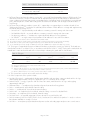
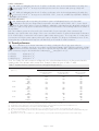
Table 5 Sto external wall insulation systems — example wind loading calculations (1)
Characteristic
Resistance to wind loads (Pa)(1)
StoTherm Classic
Rotofix Plus
Mechanical insulation
systems (4 fixings)
StoTherm Classic Rotofix
Plus Mechanical
insulation systems
(6 fixings)
StoTherm Classic
Mechanical insulation
systems
(M)
StoTherm Classic Adhesive
insulation
systems
(K)
2300
3900
3900
—
Material factor
1.5
1.5
3
—
1533
2600
1300
—
800
800
650
10000
2
2
2
9
Design pull out resistance or design
adhesive bond strength (N)
400
400
325
1111
Design pull out resistance multiplied
by the number of fixings (N)
1600
2400
1950
—
Limiting resistance (Pa)(4)
1533
2400
1300
2222
(2)
Design resistance to wind loads(Pa)
Characteristic anchor pull-out
resistance per anchor or adhesive
bond strength (N)(3)
Factor of safety
(1)
(2)
(3)
(4)
From test results (see section 5.11).
Based upon the EPS used and the manufacturing controls in place.
From site tests (see section 5.12).
The lesser of the board design pull out resistance and the resistance to wind loads for the system. This value must be higher than the value calculated from
section 5.8 (see section 5.12).
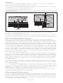
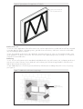
5.12 An appropriate number of site-specific pull-out tests shall be conducted on the substrate of the building (masonry,
concrete or plain sheathing board) to determine the minimum resistance to failure of the fixings. The characteristic pullout resistance should be determined in accordance with the guidance given in ETAG 014 : 2002, Annex D, using
60% of the mean value of the five smallest measured values at the ultimate load. The design pull-out resistance per
square metre is the mean pull-out resistance multiplied by the number of fixings (minimum of either 4 or 6) and divided
by a factor of safety of 2. This value must be higher than the resistances given in section 5.11.
5.13 For the StoTherm Classic Adhesive insulation systems (K), an appropriate number of site-specific bond strength
tests should be conducted on the substrate of the building to determine the minimum resistance to failure of the
adhesive. The design bond strength is the average of the five smallest measured values at the ultimate load divided by
a factor of safety of 9.
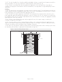
5.14 The mechanical insulation systems are not affected by the maximum deflections permitted in the design of
steel-frame structures to BS EN 1993-1-1 : 2005 and BS 5950-5 : 1998, ie span/300. Mid span deflections
should not be greater than span/300. Deflection should be limited where possible to minimise damage to the
insulation systems.
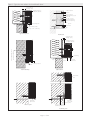
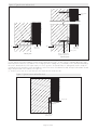
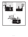
5.15 It is essential that the appropriate movement joints are incorporated into the construction to accommodate the
differential movement, for example, movement and contraction due to variation of temperature and moisture content.
This is to ensure substrate movement does not damage the insulation system.
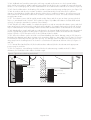
5.16 The designer should ensure that firebreaks used with the system are fixed adequately to resist the anticipated
wind loading.
Impact loading
5.17 The systems are suitable for use 1.5 m above pedestrian or floor level in areas accessible primarily to those
with a high incentive to exercise care or areas with only a small chance of accidents or misuse occurring (location
category C as defined in BS 8200 : 1985, Table 2). For areas likely to be prone to greater impacts, the advice of the
Certificate holder should be sought.
6 Behaviour in relation to fire
General
6.1 The surface spread of flame classification of the external surface of the system is given in Table 6.
Table 6 Surface spread of flame performance (1)
Maximum declared organic content of the
rendering system(2)
Reinforcement coat: 16%
Finishing coat: 14.75%
Minimum declared flame retardant of the
rendering system(2)
Euroclass according to
BS EN 13501-1 : 2007
Reinforcement coat: 20%
Finishing coats: 7.5%
B-s2,d0
(1) The effects of primer and paint need to be taken into account by the building designer.
(2) Percentage relative to the initial weight after drying.
Page 9 of 24