1
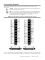
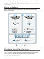
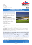
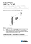
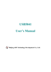
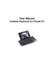
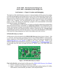
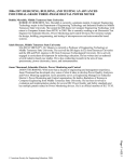
GETTING STARTED GUIDE
NI USB-7846R
R Series for USB Multifunction RIO with Kintex-7 160T FPGA
Français
日本語
Deutsch
한국어
简体中文
ni.com/manuals
This document explains how to install and configure National Instruments USB-7846R.
Safety Guidelines
Caution Do not operate the NI USB-7846R in a manner not specified in this user
manual. Product misuse can result in a hazard. You can compromise the safety
protection built into the product if the product is damaged in any way. If the product
is damaged, return it to National Instruments for repair.
Electromagnetic Compatibility Guidelines
This product was tested and complies with the regulatory requirements and limits for
electromagnetic compatibility (EMC) as stated in the product specifications. These
requirements and limits are designed to provide reasonable protection against harmful
interference when the product is operated in its intended operational electromagnetic
environment.
This product is intended for use in residential, commercial, and industrial locations. However,
harmful interference may occur in some installations or when the product is connected to a
peripheral device or a test object. To minimize interference with radio and television reception
and prevent unacceptable performance degradation, install and use this product in strict
accordance with the instructions in the product documentation.
Furthermore, any changes or modifications to the product not expressly approved by National
Instruments could void your authority to operate it under your local regulatory rules.
Caution To ensure the specified EMC performance, you must install the included
snap-on ferrite bead onto the DC power cord of the power supply as described in this
document.
Caution To ensure the specified EMC performance, operate this product only with
shielded cables and accessories.
Unpacking the Kit
Caution To prevent electrostatic discharge from damaging the device, ground
yourself using a grounding strap or by holding a grounded object, such as your
computer chassis.
Touch the antistatic package to a metal part of the computer chassis.
1.
2.
Remove the device from the package and inspect the device for loose components or any
other sign of damage.
Caution Never touch the exposed pins of connectors.
Notify NI if the device appears damaged in any way. Do not install a damaged device.
3.
Unpack any other items and documentation from the kit.
Store the device in the antistatic package when the device is not in use.
Verifying the Kit Contents
Verify that the following components are in your kit.
Figure 1. Kit Contents for the NI USB-7846R
1
2
3
4
5
6
1. Module
2. USB Cable
3. Ferrite Bead
2
|
ni.com |
NI USB-7846R Getting Started Guide
4. NI-RIO Media
5. Power Supply
6. Getting Started Guide
Installing Software
You must be an Administrator to install NI software and devices on your computer. Before
connecting the hardware, install the software in the following order.
1. Install the driver software using either the media included in your kit or by downloading
the latest version from ni.com/downloads.
2.
Follow the instructions in the installation prompts.
a) Windows 8/7/Vista users may see access and security messages during installation.
Accept the prompts to complete the installation.
3.
When the installer completes, a dialog box asks if you want to restart, shut down, or
restart later. Select Restart .
Installing the Hardware
Connecting the USB Cable
USB modules can be connected directly to the host PC, to a powered USB hub, or to an NI
PXI or PXI Express chassis featuring a USB port.
1. Connect the USB cable to the NI USB-7846R using the cable device port.
2.
Connect the other end of the USB cable to the host PC, powered hub, or chassis.
3.
Use the jackscrew on the locking USB cable to securely attach the cable to the NI
USB-7846R.
Powering the Module
Caution To ensure the specified EMC performance, install the included snap-on
1.
ferrite bead onto the DC power cord of the power supply in accordance with the
instructions provided.
Install the ferrite bead by opening the housing and looping the power supply once through
the center of the bead. Ensure the ferrite bead is as close to the end of the cable as
practical.
2.
Close the ferrite bead until the locking tabs engage securely.
NI USB-7846R Getting Started Guide |
© National Instruments |
3
Figure 2. Installing the Ferrite Bead
9-3
20 0 V
W
MA
X
2
C
V
1
x1
1. Power Supply
2. Ferrite
3.
Connect the power supply to the NI USB-7846R.
4.
Connect the other end of the power supply to a user-supplied power cord.
5.
Connect the user-supplied power cord to the appropriate power source.
6.
Turn the power switch on the NI USB-7846R to the on position.
USB Device Security Cable Slot
The security cable slot allows you to attach an optional laptop lock to your NI USB-7846R.
Note The security cable is designed to act as a deterrent, but might not prevent the
device from being mishandled or stolen. For more information, refer to the
documentation that accompanied the security cable.
Note The security cable slot on the USB device might not be compatible with all
laptop lock cables.
Refer to the documentation that accompanied the security cable for installation
instructions.
Verifying Hardware Installation
You can verify that the system recognizes the USB device by using Measurement &
Automation Explorer (MAX).
1. Launch MAX by navigating to Start»All Programs»National Instruments»MAX or by
clicking the MAX desktop icon.
2.
Expand Devices and Interfaces.
3.
Verify that the device appears under USB Devices.
If the device does not appear, press <F5> to refresh the view in MAX. If the device does
not appear after refreshing the view, visit ni.com/support for troubleshooting
information.
4
|
ni.com |
NI USB-7846R Getting Started Guide
Connecting Signals
The following figure shows the I/O connector pin assignments and locations for the NI
USB-7846R.
Caution To ensure the specified EMC performance, operate this product only
with shielded cables and accessories.
Note NI is not liable for connections that exceed any of the maximum ratings
of input or output signals on the NI USB-7846R and on the computer chassis.
For the maximum input and output ratings for each signal, refer to the NI
USB-7846R Specifications, available at ni.com/manuals.
Figure 3. NI USB-7846R Connector Pin Assignments and Locations
GND
GND
GND
DIO0
GND
DIO2
GND
DIO4
GND
DIO6
GND
DIO8
GND
DIO10
GND
DIO12
GND
DIO14
GND
DIO16
GND
DIO18
GND
DIO20
GND
DIO22
GND
DIO24
GND
DIO26
GND
DIO28
GND
DIO30
68
67
66
65
64
63
62
61
60
59
58
57
56
55
54
53
52
51
50
49
48
47
46
45
44
43
42
41
40
39
38
37
36
35
34
33
32
31
30
29
28
27
26
25
24
23
22
21
20
19
18
17
16
15
14
13
12
11
10
9
8
7
6
5
4
3
2
1
GND
AI0+
AIGND0
AI1+
DIO1
AI2+
GND
AIGND2
AI3+
GND
GND
DIO3
AI4+
AIGND4
GND
DIO5
AI5+
AI6+
GND
DIO7
AIGND6
AI7+
GND
DIO9
AISENSE
AO0
GND
DIO11
GND
AO1
AO2
AO3
DIO15
AO4
GND
AO5
AO6
AO7
GND
DIO13
DIO17
GND
DIO15
DIO13
DIO11
DIO9
DIO19
GND
DIO21
GND
DIO7
DIO6
DIO23
GND
DIO5
DIO4
DIO3
DIO25
GND
DIO27
GND
DIO2
DIO1
DIO0
DIO31
+5V
GND
DIO29
CONNECTOR 0
(DIO)
68
67
66
65
64
63
62
61
60
59
58
57
56
55
54
53
52
51
50
49
48
47
46
45
44
43
42
41
40
39
38
37
36
35
34
33
32
31
30
29
28
27
26
25
24
23
22
21
20
19
18
17
16
15
14
13
12
11
10
9
8
7
6
5
4
3
2
1
AI0–
AIGND1
AI1–
AI2–
AIGND3
AI3–
AI4–
AIGND5
AI5–
AI6–
AIGND7
AI7–
NC
AOGND0
AOGND1
AOGND2
AOGND3
AOGND4
AOGND5
AOGND6
AOGND7
DIO14
DIO12
DIO10
DIO8
DGND
DGND
DGND
DGND
DGND
DGND
DGND
DGND
+5V
CONNECTOR 1
(MIO)
TERMINAL 34
TERMINAL 1
TERMINAL 34
TERMINAL 1
TERMINAL 68
TERMINAL 35
TERMINAL 68
TERMINAL 35
The +5 V terminals on the I/O connector supply +5 V referenced to GND. Use these terminals
to power external circuitry. The NI USB-7846R is protected from overvoltage and overcurrent
NI USB-7846R Getting Started Guide |
© National Instruments |
5
conditions. Refer to the NI USB-7846R User Manual, available at ni.com/manuals, for
more information.
Where to Go Next
Refer to the following figure for information about other product tasks and associated
resources for those tasks.
Worldwide Support and Services
The National Instruments website is your complete resource for technical support. At ni.com/
support, you have access to everything from troubleshooting and application development
self-help resources to email and phone assistance from NI Application Engineers.
6
|
ni.com |
NI USB-7846R Getting Started Guide
Visit ni.com/services for NI Factory Installation Services, repairs, extended warranty, and
other services.
Visit ni.com/register to register your National Instruments product. Product registration
facilitates technical support and ensures that you receive important information updates from
NI.
National Instruments corporate headquarters is located at 11500 North Mopac Expressway,
Austin, Texas, 78759-3504. National Instruments also has offices located around the world.
For telephone support in the United States, create your service request at ni.com/support or
dial 1 866 ASK MYNI (275 6964). For telephone support outside the United States, visit the
Worldwide Offices section of ni.com/niglobal to access the branch office websites, which
provide up-to-date contact information, support phone numbers, email addresses, and current
events.
NI USB-7846R Getting Started Guide
|
© National Instruments |
7
Refer to the NI Trademarks and Logo Guidelines at ni.com/trademarks for information on National Instruments trademarks.
Other product and company names mentioned herein are trademarks or trade names of their respective companies. For patents
covering National Instruments products/technology, refer to the appropriate location: Help»Patents in your software, the
patents.txt file on your media, or the National Instruments Patent Notice at ni.com/patents. You can find information about
end-user license agreements (EULAs) and third-party legal notices in the readme file for your NI product. Refer to the Export
Compliance Information at ni.com/legal/export-compliance for the National Instruments global trade compliance policy and
how to obtain relevant HTS codes, ECCNs, and other import/export data.
© 2014 National Instruments. All rights reserved.
376846A-01
Mar14