1
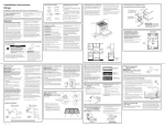
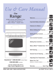
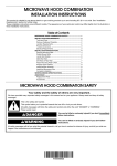
USER MANUAL & INSTALLATION INSTRUCTIONS GOURMET FREESTANDING RANGE VITROCERAMIC COOKTOP ELECTRIC OVEN IMPORTANT SAFETY INSTRUCTIONS Carefully read the following important information regarding installation safety and maintenance. Keep these instructions for future reference. 2014-04-13 MAAN2201-10 Table of Contents Table of Contents .................................................................................................................... 2 Safety Requirements ............................................................................................................... 3 Parts Supplied ......................................................................................................................... 9 Ventilation Requirements....................................................................................................... 10 Electrical Requirements ......................................................................................................... 13 Advance Preparation ............................................................................................................. 14 Tools and Parts .................................................................................................................. 14 Range Dimensions ............................................................................................................. 14 Unpack Range ................................................................................................................... 16 Install Leveling Feet and Back Panel ................................................................................. 16 Install Anti-Tip Bracket ....................................................................................................... 17 Installation Instructions .......................................................................................................... 19 Electrical Connection ......................................................................................................... 19 Surface Cooking .................................................................................................................... 22 Location of the Burners ...................................................................................................... 22 Description of Symbols ...................................................................................................... 22 Setting Surface Controls .................................................................................................... 23 Surface Cooking Utensils ................................................................................................... 24 Oven Cooking ........................................................................................................................ 25 Setting Oven Clock and Timer ........................................................................................... 25 Setting Oven Controls ........................................................................................................ 26 Cooking Instructions........................................................................................................... 29 Care and Cleaning ................................................................................................................. 30 Solutions to Common Problems ............................................................................................ 33 Warranty ................................................................................................................................ 35 2 Safety Requirements IMPORTANT SAFETY NOTICE READ ALL INSTRUCTION BEFORE INSTALLING AND OPERATING THIS APPLIANCE We have provided many important safety messages in this manual and on your appliance. Always read and obey all safety messages. This is the safety alert symbol. This symbol alerts you to potential hazards that can kill or hurt you and others. All safety messages will follow the safety alert symbol and either the word “DANGER” or “WARNING.” These words mean: You can be killed or seriously injured if you don't immediately follow instructions. You can be killed or seriously injured if you don't follow instructions. All safety messages will tell you what the potential hazard is, how to reduce the chance of injury, and what can happen if the instructions are not followed. • Remove all tape and packaging before using the appliance. Never allow children to play with packaging material. Do not remove the model/serial plate attached to the appliance. • Be sure your appliance is properly installed and grounded by a QUALIFIED TECHNICIAN in accordance with the National Fuel Gas Code ANSI Z223.1—latest edition in the United States, or in Canada CAN/CGA B149.1, and CAN/CGA B149.2, and the National Electrical Code ANSI/NFPA No. 70—latest edition in United States, or in Canada CSA Standard C22.1, Canadian Electrical Code, Part 1, and local code requirements. Install only as per installation instructions provided in the literature package for this appliance. 3 If the information in this manual is not followed exactly, a fire or explosion may result causing property damage, personal injury or death. • FOR YOUR SAFETY: - Do not store or use gasoline or other flammable vapors and liquids in the vicinity of this or any other appliance. • Installation and service must be performed by a qualified installer. Ask your dealer to recommend a qualified technician and an authorized repair service. Know how to disconnect the electrical power to the appliance at the circuit breaker or fuse box in case of an emergency. • Do not repair or replace any part of the appliance unless specifically recommended in the manuals. All other servicing should be done only by a qualified technician. This may reduce the risk of personal injury and damage to the appliance. • Proper Installation – The range, when installed, must be electrically grounded in accordance with local codes or, in the absence of local codes, with the National Electrical Code, ANSI/NFPA 70. In Canada, the range must be electrically grounded in accordance with Canadian Electrical Code. Be sure the range is properly installed and grounded by a qualified technician. • Disconnect power before servicing. • Never modify or alter the construction of the appliance by removing panels, wire covers or any other part of the product. • Injuries may result from the misuse of appliance doors or drawers such as stepping, leaning, or sitting on the doors or drawers. 4 • Overhead range hoods, which operate by blowing a downward air flow on to a range, shall not be used in conjunction with gas ranges other than when the hood and range have been designed, tested and listed by an independent test laboratory for use in combination with each other. • Ensure that the room is well ventilated by keeping the air intakes open and in good working order or by installing an extractor hood with discharge pipe. If the appliance is used intensively for a long time the effectiveness of the ventilation will have to be increased, for example by opening a window or increasing the power of any electric extractor fan. • Flammable materials should not be stored on the appliance or near surface units. This includes paper, plastic and cloth items, such as cookbooks, plastic ware and towels, as well as flammable liquids. Do not store explosives, such as aerosol cans, on or near the appliance. Flammable materials may explode and result in fire or property damage. • Maintenance – Keep range area clear and free from combustible materials, gasoline, and other flammable vapors and liquids. • Storage in or on the Range – Flammable materials should not be stored in an oven or near surface units. Do not store items of interest to children in the cabinets above the appliance or on the backguard of a range. Children should not be left alone or unattended in the area where appliance is in use. Do not allow children to climb or play around the appliance. They should never be allowed to sit or stand on any part of the appliance. Children climbing on the appliance to reach items could be seriously injured. • DO NOT TOUCH THE COOKING SURFACE, THE BURNERS, GRATES OR ANY AREAS NEAR THEM. Surface burners or appliance may be hot even though flames are not visible. Areas near surface burners or appliance may become hot enough to cause burns. During and after use, do not touch, or let clothing or other flammable materials touch these areas until they have had sufficient time to cool. 5 • Do not wear loose-fitting or hanging garments while using the appliance. Do not let clothing or other flammable materials contact hot surfaces. • Smother grease fires with a pan lid, or use baking soda, a dry chemical or foam-type extinguisher. • • Use an extinguisher ONLY if: - You know you have a Class A, B, C extinguisher, and you already know how to operate it. - The fire is small and contained in the area where it is started. - The fire department is being called. - You can fight the fire with your back to an exit. When heating fat or grease, watch it closely. Fat or grease may catch fire if allowed to become too hot. • Use only dry potholders. Moist or damp potholders on hot surfaces may result in burns from steam. Do not let potholders touch hot heating elements, the flame or burners. Do not use a towel or other bulky cloth instead of a potholder. • Do not heat unopened food containers. Buildup of pressure may cause the container to burst and result in injury. • Stepping, leaning or sitting on this appliance can result in serious injuries and also cause damage to the appliance. • Never use this appliance as a space heater to heat or warm the room. Doing so may result in carbon monoxide poisoning and overheating of the oven. • Know which knob controls which surface burner. Visually check that the burner has lit. Then adjust the flame so it does not extend beyond the edge of the utensil. 6 • Clean the appliance regularly to keep all parts free of grease that could catch fire. Exhaust fan ventilation hoods and grease filters should be kept clean. Do not allow grease to accumulate on hood or filter. Greasy deposits in the fan could catch fire. When cooking food turn the hood, fan on. Refer to hood manufacturer’s instructions for cleaning. • Utensil handles should be turned inward and not extend over adjacent surface burners. To reduce the risk of burns, ignition of flammable materials, and spillage due to unintentional contact with the utensil, the handle of the utensil should be positioned so that it is turned inward, and does not extend over adjacent surface burners. • Never leave surface burners unattended at high heat settings. Boil overs cause smoke and greasy spillovers that may ignite, or a pan that has boiled dry may melt. • Do not use aluminum foil to line any part of the appliance. Use aluminum foil only to cover food during cooking. Improper installation of these liners may result in risk of electric shock or fire. • Only certain types of glass, glass/ceramic, ceramic, earthenware, or other glazed utensils are suitable for appliance service without breaking due to the sudden change in temperature. Check the manufacturer’s recommendations for appliance use. • Do not use decorative surface burner covers. If a burner is accidentally turned on, the decorative cover will become hot and possibly melt. You will not be able to see that the burner is on. Burns will occur if the hot covers are touched. Damage may also be done to the range or burners because the covers may cause overheating. Air will be blocked from the burner and cause combustion problems. • Use the proper pan sizes. This appliance is equipped with surface units of different sizes. Select utensils having flat bottoms large enough to cover the surface unit. The use of undersized utensils will expose a portion of the surface heating unit to direct contact and may result in ignition of clothing. Proper relationship of utensil to the surface unit will also improve efficiency. 7 TO REDUCE THE RISK OF TIPPING OF THE RANGE, THE RANGE MUST BE SECURED BY PROPERLY INSTALLED ANTI-TIP DEVICES. TO CHECK IF THE DEVICES ARE INSTALLED PROPERLY, SLIDE RANGE FORWARD, LOOK FOR ANTI-TIP BRACKET SECURELY ATTACHED TO FLOOR OR WALL, AND SLIDE RANGE BACK SO REAR RANGE FOOT IS UNDER ANTI-TIP BRACKET. • The range will not tip during normal use. However, the range can tip if you apply too much force or weight to the open door without having the anti-tip bracket fastened down properly. TIP OVER HAZARD A child or adult can tip the range and be killed. Connect anti-tip bracket to rear range foot. Reconnect the anti-tip bracket, if the range is moved. See the installation instructions for details. Failure to follow these instructions can result in death or serious burns to children and adults. 8 Parts Supplied 7 x Knobs 1 x Optional Backsplash 4 x Feet 2 x Oven Racks 1 x Grill Set (Basin + Anti-Splash) 1 x Rack Puller 1 x Anti-Tip Bracket 2 x Screws and Anchors 9 Ventilation Requirements The range should have proper ventilation in order to keep the unit operating properly and maintain the temperature of immediate surroundings within safe limits. Check your local building codes as they may vary from the general rules outlined in this guide. It is recommended that a hood be installed above the range that is rated no less than 400 CFM. This will provide adequate ventilation for this range. Mounting distance of your ventilation is outlined by the manufacturer of your hood. • Observe all governing codes and ordinances. Do not obstruct flow of combustion and ventilation air. • It is the installer’s responsibility to comply with installation clearances specified on the model/serial rating plate. • The range should be located for convenient use in the kitchen. • Recessed installations must provide complete enclosure of the sides and rear of the range. • To eliminate the risk of burns or fire by reaching over heated surface units, cabinet storage space located above the surface units should be avoided. If cabinet storage is to be provided, the risk can be reduced by installing a range hood or microwave hood combination with minimum 400 CFM that projects horizontally a minimum of 5" (12.7 cm) beyond the bottom of the cabinets. (See Figure 1) • If a range hood is installed above the appliance, maintain a 30” minimum clearance between cooking surface and bottom of range hood. The range hood must be connected directly to flues or to the outside. (See Figure 1) • Avoid placing cabinetry directly above the appliance when possible. If cabinetry is used above the cooking surface, use cabinets no more than 13″ deep. Make sure the wall coverings, countertop 10 and cabinets around the appliance can withstand heat up to 200º F (93°C) generated by the appliance. (See Figure 1) • Cabinet opening dimensions that are shown must be used. Given dimensions are minimum clearances. (See Figure 1) • Working areas adjacent to the range should have 18″ minimum clearance between countertop and cabinet bottom. (See Figure 1) • All openings in the wall or floor where range is to be installed must be sealed. • Contact a qualified floor covering installer to check that the floor covering can withstand at least 200°F (93°C). • Use an insulated pad or ¼" (0.64 cm) plywood under range if installing range over carpeting. • The floor anti-tip bracket must be installed. To install the anti-tip bracket shipped with the range, see “Install Anti-Tip Bracket” section. • Grounded electrical supply is required. See “Electrical Requirements” section. 11 MOBILE HOME – ADDITIONAL INSTALLATION REQUIREMENTS • The installation of this range must conform to the Manufactured Home Construction and Safety Standard, Title 24 CFR, Part 3280 (formerly the Federal Standard for Mobile Home Construction and Safety, Title 24, HUD Part 280). When such standard is not applicable, use the Standard for Manufactured Home Installations, ANSI A225.1/NFPA 501A or with local codes. In Canada, the installation of this range must Figure 1 conform with the current standards CAN/CSAA240-latest edition, or with local codes. To avoid damage to your cabinets, check with MOBILE HOME INSTALLATIONS REQUIRE: your builder or cabinet supplier to make sure • that the materials used will not discolor, home, it must be secured to the floor during delaminate or sustain other damage. This oven transit. Any method of securing the range is has been designed in accordance with the adequate as long as it conforms to the requirements of UL and CSA International and standards listed above. complies with the maximum allowable wood cabinet temperatures of 194°F (90°C). 12 When this range is installed in a mobile Electrical Requirements instructions in the “Electrical Connection” section. If you wish to install this appliance directly to the main (without a plug), it must be installed by a qualified service technician. Electrical Shock Hazard • Do not use an extension cord. 2-prong adapter or an extension cord. If a 2- Failure to follow these instructions can prong wall receptacle is the only available result in death, fire, or electrical shock. outlet, it is the personal responsibility of the DO NOT operate this appliance using a consumer to have it replaced with a properly • grounded 4-prong wall receptacle installed by Any additions, changes or conversions a qualified electrician. required in order for this appliance to satisfactorily meet the application needs must • be made by a qualified service technician in Severe shock, or damage to the range may occur if the range is not installed by a accordance with the manufacturer’s qualified installer or electrician. instructions and all codes and requirements of the authority having jurisdiction. Failure to follow the instructions could result in serious • injury or property damage. The qualified recommendation to connect to a 50 Amp agency performing this work assumes power supply. It is 220-240V/50-60Hz. With responsibility for the conversion. • • Total Input Power is 11.7kw (48.75A). A dedicated circuit, protected by a minimum 50 This appliance is not supplied with a plug. amp time delay fuse or circuit breaker is If you wish to install this appliance with a plug, required. it must installed by a qualified service technician. The plug must be a 4-prong, 3- • phase plug that is designed specifically for be properly grounded. freestanding ranges. • For personal safety, the appliance must • This appliance can be installed directly to See the “Installation Instructions” packaged with this appliance for complete the main (without a plug). To do so, follow installation and grounding instructions. 13 Advance Preparation Tools and Parts Gather the required tools and parts before starting installation. Read and follow the instructions provided with any tools listed here. ■ Tape measure PARTS SUPPLIED: ■ Phillips screwdriver Check that all parts are included. ■ Flat blade screwdriver ■ 3 - Oven racks ■ 1/8” flat blade screwdriver ■ 1 Anti-tip brackets ■ Level ■ 2 plastic anchors ■ Hand or electric drill ■ 2 screws ■ Wrench or pliers ■ 1/8” (3.2 mm) drill bit (for wood floors) The anti-tip bracket must be securely mounted ■ Marker or pencil to the floor. Thickness of flooring may require ■ 3/16” (4.8 mm) carbide-tipped masonry drill longer screws to anchor bracket to subfloor. bit (for concrete/ceramic floors) PARTS NEEDED Check local codes. Check existing electrical supply. See “Electrical Requirements” section. Range Dimensions • Avoid placing cabinetry directly above the appliance when possible. If cabinetry is used above the cooking surface, use cabinets no more than 13″ deep. Make sure the wall coverings, countertop and cabinets around the appliance can withstand heat up to 200º F (93°C) generated by the appliance. (See Figures 1 and 2) • Cabinet opening dimensions that are shown must be used. Given dimensions are minimum clearances. (See Figures 1 and 2) 14 • Working areas adjacent to the range should have 18″ minimum clearance between countertop and cabinet bottom. (See Figures 1 and 2) Figure 2 Note: This height measurement does not include leveling feet. 15 Unpack Range Install Leveling Feet and Back Panel Excessive Weight Hazard Tip Over Hazard A child or adult can tip the range and be killed. Use two or more people to move and install range. Failure to follow these instructions can result in death or serious burns to children and adults. 1. Remove shipping materials from the 6. Install the leveling feet one at a time. range. DO NOT remove protective film The leveling feet can be found in one of covering the appliance. DO NOT the boxes that was inside the oven. remove tape securing the drawer. 7. Place cardboard or hardboard in front 2. Remove oven racks and parts package of range. Using 2 or more people, from inside oven. stand range back up onto cardboard or hardboard. 3. Place range on its back; take four (4) Lshaped cardboard corners from the 8. Remove the protective film covering the carton. Stack one cardboard corner on appliance. Remove tape securing the top of another. Repeat with the other 2 drawer. corners. 9. The stainless steel back panel can now be installed. Place panel into the 4. Place the four (4) L-shaped cardboard corners lengthwise on the floor behind grooves on the top rear of the range. the range to support the range when it Then affix the panel to the range using is laid on its back. the screws provided. 5. Using 2 or more people firmly grasp the range and gently lay it on its back on the cardboard corners. 16 Install Anti-Tip Bracket Tip Over Hazard A child or adult can tip the range and be killed. Connect anti-tip bracket to rear range foot. Reconnect the anti-tip bracket, if the range is moved. Failure to follow these instructions can result in death or serious burns to children and adults. Contact a qualified floor covering installer for the procedure of drilling mounting holes through your type of floor covering. Assemble the required tools and parts before starting installation. Read and follow the instructions provided with any tools listed here. Anti-tip bracket concrete / ceramic floors: 3/16" ( 4.6 2 plastic anchors mm) masonry drill bit 2 screws Tools needed for installation: wood floors: 1/8" (3.2 mm) drill bit hand or electric drill flat-blade screwdriver hammer measuring tape masking tape Parts supplied for installation (See Figure 3): Figure 3 Install the anti-tip bracket to hold the left rear leg of the slide-in range. Follow these steps to secure the range to the floor before moving the range into final operating position. 17 1. Before moving range, slide range onto 10. Align anti-tip bracket holes with holes in shipping base cardboard or hardboard. floor. Fasten anti-tip bracket with screws provided. (See Figure 6) 2. Place this template on floor in cabinet 11. Move range close to opening. Remove opening so that the left edge is against shipping base, cardboard or hardboard cabinet and top edge is against rear from under range. Connect power wall, molding or cabinet. (See Figure 4) supply cord as described in Installation Instructions. Move range into final 3. Tape template in place. position making sure rear leveling leg slides into anti-tip bracket. (See Figure 4. If countertop is deeper than 25" (63.5 7) cm), measure and mark a distance of 25" (63.5 cm) in from front of 12. Continue installing your range following countertop and align template with the installation Instructions. mark. (See Figure 4) 5. If countertop is not flush with cabinet Figure 4 opening edge, align template with overhang. 6. If cabinet opening is wider than Figure 5 specified in Installation Instructions, adjust template so range will be centered in cabinet opening. 7. To mount anti-tip bracket to wood floor, drill two 1/8" (3.2 mm) holes at the positions marked on the bracket template. (See Figure 5) 8. Remove template from floor. 9. Tap plastic anchors into holes with a hammer. Figure 6 18 Figure 7 Installation Instructions Electrical Connection Electrical Shock Hazard Do not use an adapter. Do not use an extension cord. Failure to follow these instructions can result in death, fire, or electrical shock. Electrical connection must be performed by a qualified service technician in accordance with the kit instructions and all local codes and requirements. • This appliance is not supplied with a plug and needs to be connected directly to the electrical mains. • If you wish to install this appliance with a plug, it must installed by a qualified service technician. The plug must be a 4-prong, 3-phase power plug that is designed specifically for ranges and ovens. Electrical Requirements: 220-240V/50-60Hz. With recommendation to connect to a 50 Amp power supply. ELECTRICAL SPECIFICATIONS SYSTEM WATTAGE Oven Light 3 x 25W Upper Heating Element 2395W Bottom Heating Element 1960W Grill Heating Element 3158W Convection Heating Element 2 x 1250W Ventilator Motor 2 x 20W Cooling Fan 18W 19 BEFORE MAKING THE ELECTRICAL CONNECTION, MAKE SURE THAT: • The safety circuit-breaker and the electrical system are able to with stand the load of the appliance. See rating label on back of range. • Rating plate is located on back of range should you need to verify any of the electrical requirements. • The power supply system has a ground connection in good working order in accordance with the regulations in force. • The electrical socket is easily accessible with the appliance installed. In all cases, the power supply lead must be positioned so that it does not reach a temperature of 50oC above the room temperature at any point. • The manufacturer is not liable for any direct or indirect damage caused by faulty installation or connection. It is therefore necessary that all installation and connection operations are carried out by qualified personnel complying with the local and general regulations in force. CONNECTION OF THE RANGE WIRES TO THE MAINS 1) This appliance is equipped with the following wires: One black wire (L1 - Live) and one red wire (L2 - Live) One yellow /green (Ground) 2) Follow the diagram below to know how to connect the freestanding range wires to the electrical main wires of the home. (See Figure 8) 3) The black and red wires can be connected to the electrical main wires of the home in one of the following three configurations: 20 Configuration 1: L1 to L1 and L2 to L2 Configuration 2: L1 to L1 and L2 to L3 Configuration 3: L1 to L2 and L2 to L3 Figure 8 4) Never use reductions, shunts, or adaptors which can cause overheating or burning. 5) After carrying out the connection to the mains, check that the supplying cable does not come into contact with parts subject to heating. 21 Surface Cooking Location of the Burners A. Single cooking zone - 1200W B. Single cooking zone - 2200W C. Single cooking zone - 1800W D. Power & Residual Heat Warning Lights Figure 9 Description of Symbols Figure 10 BEFORE FIRST USE: 1. Before cooking for the first time the ceramic glass has to be cleaned. Remove any labels and protective sheeting. 2. Place a saucepan of water on each of the front burners and switch them on the high for at least 30 minutes. 3. After 30 minutes switch the front burners off, place a saucepan of water on each of the rear and the center burners. Switch them on high for at least 30 minutes. 4. This procedure is necessary in order to evaporate any protective oils and humidity that may have collected during the manufacturing process and it will enable the electronic control circuits to operate properly. 22 Setting Surface Controls Figure 11 1. Turn the control knob to the desired position (low to high). (See Figure 11) 2. Adjustment is continuous so the cooking zone will operate at any intermediate setting between low and high. 3. Once the cooking zone is hot, the LED corresponding to the zone illuminates. 4. To switch off the cooking zone by turn the knob, in either direction to the “OFF” position. 5. The residual heat warning light remains illuminated when the temperature of the ceramic glass surface is hot and will switch off once the surface temperature has cooled. 23 Surface Cooking Utensils Do not place plastic items such as salt and pepper shakers, spoon holders or plastic wrappings on top of the appliance when it is in use. These items could melt or ignite. Potholders, towels or wood spoons could catch fire if placed too close to a heat. Note: Always use a utensil for its intended purpose. Follow manufacturer’s instructions. Some utensils were not made to be used in the oven or on the cooking surface. For best results and energy savings, only use pans suitable for electric cooking. The bottom of the pan must be very thick and perfectly flat. Before placing on the burner, make sure that the pan and burner, are perfectly clean and dry. To avoid scratching of the ceramic glass surface, never use cast-iron pans or pans with a rough bottom. POT SIZES: To avoid wasting energy, make sure that the diameter of the pan bottom is 20mm bigger than the circle marked on the hotplate. The pot sizes stated in the table below are suitable for your ceramic surface. Solids pots and pans with flat bottoms are recommended for efficient cooking. (See Figure 9) BURNER ZONE ZONE DIAMETER MINIMUM DIAMETER OF PAN Cooking Zone A 140 mm (5 1/2 inches) 160 mm (6 1/4 inches) Cooking Zone B 220 mm (8 5/8 inches) 240 mm (9 3/8 inches) Cooking Zone C 180 mm (7 1/8 inches) 200 mm (7 7/8 inches) 24 Oven Cooking Setting Oven Clock and Timer Figure 12 DIGITAL CLOCK COOKING WITH THE TIMER This model has a digital display 24 hour clock By selecting the desired end time, cooking with 3 control buttons. When first connected to time, temperature and cooking mode you can power (or after a power outage) the screen will set the oven to cook your dish automatically. display ’12:00’ and the bar above the (See Figure 12) symbol will flash. (See Figure 12) 1) Press the function button until the bar ADJUSTING THE CLOCK above the To set the correct time, press the + or – button symbol flashes, then press + or – to set the cooking time. to advance forward or backward until the 2) Press the function button until the bar correct time is displayed. When finished you above the can press the function button, otherwise wait 5 press + or – to set the desired end time. seconds it will stay at the set time. (See symbol flashes, then 3) Set the temperature and cooking mode Figure 12) using the thermostat and selector knobs. MANUAL OPERATION Press the function button to select manual operation. 25 Setting Oven Controls Figure 13 Figure 14 Selection of cooking temperature is carried out by turning the knob clockwise to the required temperature. The warning light will illuminate during the heating process. Once the oven reaches desired temperature, the light will go out. Regular flashing means that the oven temperature is being maintained at the programmed level. OVEN LIGHT INDICATOR The lamp of the oven is on. During oven operation the lamp will always remain on. TRADITIONAL COOKING (Upper and Lower element) THERMOSTAT SELECTOR SWITCH FROM 60° C (140° F) TO MAX The heat is provided from the top and bottom elements. The oven must be preheated before the food is placed inside. Static cooking provides optimum results with: cakes, pizzas, bread and for gentle slow cooking of casseroles. Characteristics of static cooking: heat provided from above and below, cooking is possible only on middle shelf and should be centrally located in the oven. 26 DELICATE COOKING (Lower element and Fan) THERMOSTAT SELECTOR SWITCH FROM 60° C (140° F) TO MAX Ideal for pastries and cakes with wet covering and little sugar and damp desserts in moulds. Excellent results can also be achieved in completing cooking at the bottom and with dishes requiring heat in the lower area in particular. The plate is best inserted at bottom level. UPPER ELEMENT COOKING THERMOSTAT SELECTOR SWITCH FROM 60° C (140° F) TO MAX This is best used to brown select dishes at the end of cooking. GRILL COOKING (Grill element) THERMOSTAT SELECTOR SWITCH FROM 60° C (140° F) TO MAX The use of the grill element is best reserved for: melting cheese, toasting, and browning. The cooking time should be no longer than 5 minutes. To operate, please select Full Grill Function along with the temperature. FAN ASSISTED GRILL COOKING (Grill element and Fan) THERMOSTAT SELECTOR SWITCH FROM 60° C (140° F) TO 200° C (392° F) Best used for grilling meats, vegetables, and poultry. Preheat the oven, place food on a grilling rack or backing tray and place in the middle of the oven. Other racks can be used simultaneously using this method. CONVECTION COOKING (Cooking element & Fan) THERMOSTAT SELECTOR SWITCH FROM 60° C (140° F) TO MAX This method allows even-heat multi-rack cooking for various types of foods with the appropriate cooking times for each dish. The oven must be preheated before the foods are placed inside. Use the ‘Fan Forced’ function to operate. 27 DEFROST (Bottom fan) All types of food can be defrosted by circulating air at room temperature: cakes, cream, fruit, etc. For foods such as: meat, fish, and bread you will want to set the fan temperature to 175-200° C (347-392° F). 28 Cooking Instructions Setting: Traditional Cooking (add time for preheat) Convection Cooking (add time for preheat) Setting: Grill Cooking Food: Rack Level (See Figure 33) 2-3 2-3 Temperature (Fahrenheit): 410-450 410-450 Time (mins): 2 2 2 2 2 1 2 1-2 350-400 410-460 340-400 340-400 340-400 280-340 340-400 340-400 Pizza Short Pastry Fruit Cake Browning Lasagna Oven-Baked Pasta Roast Veal Beef Pork Chicken Duck Goose/Turkey Lamb Fish 1-2 1-2 1-2 3-4 2-3 2 410-450 340-400 340-400 140 375-410 375-410 30-40/lb 30-40/lb 30-40/lb 45-60 45-60 45-60 15/lb Depends on dimension 40-45 15-20 20-30 5 20-25 25-30 2 2 2 2 2 2 2 2-3 300-350 350-375 300-325 350 325-350 300-325 300-350 300-350 Pizza Sponge Cake Fruit Cake Bread Food: 2-3 2-3 2-3 1-2 Rack Level (See Figure 33) 4 3 3 4 4 3 4 4 4 4 410-475 375-425 350-375 425-475 1st Side Cook Time (mins): 7-9 9-11 9-11 2-3 7-9 9-14 7-9 7-9 5-6 2-4 Lasagna Oven-Baked Pasta Roast Veal Beef Pork Chicken Duck Goose/Turkey Lamb Fish Pork Chops Fillet (Pork) Fillet (Beef) Liver Veal Chicken Sausages Meatballs Fish Fillet Toast 29 30 40 65-90 65-90 70-100 70-90 100-160 160-240 100-130 Depends on dimension 30-50 25-35 40-50 7 2nd Side Cook Time (mins): 5-7 5-9 9-11 2-3 5-7 9-11 5-6 5-6 3-4 2-3 Care and Cleaning ELECTRICAL SHOCK HAZARD BURN HAZARD To avoid possible burns use care when cleaning the appliance. DO NOT attempt to clean the appliance whenever the oven or burner heads are still hot. To avoid possible burns DO NOT attempt any of the following cleaning instructions before turning OFF ALL of the surface burners and allowing them to cool. IMPORTANT: Always follow label instructions on cleaning products. • Control Knobs For general cleaning, use hot, soapy water and a cloth. For more difficult soils and built-up grease, apply a liquid detergent directly onto the soil. Rinse with a damp cloth and dry. DO NOT use steel wool or acidic cleaners on the knobs as they can scratch. • Stainless Steel Clean stainless steel with hot, soapy water and a dishcloth. Rinse with clean water and a cloth. Do not use cleaners with high concentrations of chlorides or chlorines. Do not use harsh scrubbing cleaners. Only use kitchen cleaners that are especially made for cleaning stainless steel. • Inside Oven This appliance does NOT have a self-cleaning feature. DO NOT attempt to clean the appliance whenever the oven is still hot. Use an appropriate cleaning product designed specifically to clean the inside of ovens. IMPORTANT: Always follow label instructions on cleaning products. 30 • Cleaning Interior Lower Grill Element To remove the element, support one side with your hand while removing the retainer with the other. When cleaning, make sure not to apply excessive force on the element as it is fragile. Reposition the element and secure the retainer back in place. DO NOT use the oven with the grill element hanging down – it must be repositioned after cleaning. • Storage Drawer Make sure drawer is cool and empty before cleaning. Use a mild detergent. • Oven Door Exterior Use a glass cleaner and a soft cloth or sponge. Apply glass cleaner to soft cloth or sponge, not directly on panel. • Removing and Cleaning the Oven Door For normal range use, it is not suggested to remove the oven door. However, if removal is necessary, make sure the oven is off and cool. The oven door is heavy. Follow these instructions. Open the door fully. Lift up and push the small levers located on the two hinges all the way back. While holding the door on each side, shut the door until it touches the levers. Then continue closing the door until it is about 4 inches (10cm) from being fully closed. Pull the door towards you, pulling it out of its seat. Door will gently come away from the oven. (See Figure 15) To replace the door, perform the reverse of the above procedure. Please note: If door does not come away from oven easily, do not force it. Figure 15 31 • Changing the Interior Oven Light Bulb ELECTRICAL SHOCK HAZARD Ensure that the appliance is switched off before replacing the lamp to avoid possible electric shock. Remove the glass cover by turning counter clockwise. (See Figure 16) Replace bulb with a high temperature bulb able to withstand 600 degrees and that meets the following criteria: 240V 25W Type: E-14 Figure 16 32 Solutions to Common Problems IMPORTANT Before calling for service, review this list. It may save you both time and expense. This list includes common experiences that are not the result of defective workmanship or material in your appliance. Electrical Shock Hazard Plug into a grounded 3 prong outlet. Do not remove ground prong. Do not use an adapter. Do not use an extension cord. Failure to follow these instructions can result in death, fire, or electrical shock. NOTHING WILL OPERATE ■ Is the electrical supply disconnected? Verify that electrical wires are connected to the mains properly. See “Electrical Connection” section. If the problem continues, contact a qualified technician. ■ Household fuse blown or circuit breaker tripped? Replace the fuse or reset the circuit breaker. If the problem continues, contact a qualified technician. SURFACE BURNERS WILL NOT OPERATE ■ Is the control knob set correctly? Push in knob before turning to a setting. EXCESS HEAT AROUND COOKWARE ON COOKING SURFACE ■ Is the cookware the proper size? Use cookware about the same size as the surface cooking area, element or surface burner. Cookware should extend 20mm outside the cooking area. 33 COOKTOP COOKING RESULTS NOT WHAT EXPECTED ■ Is the proper cookware being used? See “Surface Cooking Utensils” section. ■ Is the control knob set to the proper heat level? See “Setting Surface Controls” section. ■ Is the range level? Level the range. See the “Unpack Range / Install Leveling Feet and Back Panel” section. OVEN WILL NOT OPERATE ■ Are the oven controls set correctly? See “Setting Oven Controls” section. COOLING FAN RUNS DURING BAKING AND BROILING ■ It is normal for the fan to automatically run while the oven is in use and for some time after to cool. OVEN TEMPERATURE TOO HIGH OR TOO LOW ■ Was the oven preheated? See “Cooking Instructions” section. ■ Are the racks positioned properly? See “Cooking Instructions” section. ■ Is there proper air circulation around bakeware? See “Cooking Instructions” section. ■ Is the batter evenly distributed in the pan? Check that batter is level in the pan. ■ Is the proper length of time being used? Adjust cooking time. ■ Has the oven door been opened while cooking? Oven peeking releases oven heat and can result in longer cooking times. ■ Are baked items too brown on the bottom? Move rack to higher position in the oven. ■ Are pie crust edges browning early? Use aluminum foil to cover the edge of the crust and/or reduce baking temperature. 34 Warranty Subject to the limitations, exclusions and disclaimers hereof, AMS warrants exclusively to the original purchaser (the “Purchaser”) of this Ancona product (the “Product”) that it shall be free from defects in material or workmanship (the “Limited Product Warranty”). The duration of the Limited Product Warranty is 12 months from the date of original purchase (the “Warranty Period”). The Limited Product Warranty does not extend to commercial or institutional use or installation and to residential or domestic use or installation outside of Canada and the USA. It is not transferable or assignable to any person. Any failure of the Product that is not traceable to a defect in material or workmanship is not covered by the Limited Product Warranty. These non-warrantable items include, but are not limited to: (i) consumable and accessory parts; such as light bulbs; (ii) service outside of Canada and the USA; (iii) damage caused during shipping, handling or installation; (iv) labour costs related to installation, removal, reinstallation costs or other contingent expense; or (v) routine replacement of parts due to normal wear and tear of the Product. If the Purchaser discovers within the Warranty Period a defect in material or workmanship, the Purchaser shall promptly notify AMS in accordance with the Warranty Claim Procedure set forth below. Within a reasonable time after such notification, AMS shall, at no charge to the Purchaser: (i) perform any repair or replacement of parts that it determines is necessary or useful to correct any defect in material or workmanship; or (ii) replace the original Product with a new Product, the whole at AMS’ sole and absolute discretion. The remedy provided above shall be the Purchaser’s sole and exclusive remedy and AMS' sole and exclusive obligation under the Limited Product Warranty. Products or parts that are new or reconditioned to perform as new, shall be exchanged by AMS upon receipt of the original Product or parts from the Purchaser and, upon the completion of such exchange, the original Product or parts shall become AMS’ property. The Warranty Period shall not be extended due to suspension of the use of the Product because of repair, replacement, examination or for any other reason. Subject to the Purchaser’s compliance with the Warranty Claim Procedure set forth below, transportation and installation of warranty replacements shall be performed at AMS’ cost, and AMS shall bear the risk of loss or damage to returned Product or parts while in transit. AMS’ Limited Product Warranty shall be automatically void if: (i) any repair, alteration, modification, customization, disassembling, addition or any other work is performed on the Product by any person not authorized by AMS to do so; (ii) any alleged material defect, including deterioration or wear, is a result of failure to observe the manufacturer’s instructions or guidelines, abuse, misuse, improper operation, care or maintenance, unusual physical or electrical stress and/or power surges, brown-out, chemical abrasion or improper chemical or environmental conditions, leaking, fire, lightning, force majeure or superior force, accident, error, negligence, or is a result of use for non-domestic or non-residential purposes or for any purpose other than the Product’s intended purpose; (iii) the Product is operated in conjunction with accessories, other products, ancillaries or peripheral equipments or substances that have not been previously approved in writing or validated by AMS; or (iv) Purchaser fails to comply with the Warranty Claim Procedure set forth below. THE LIMITED PRODUCT WARRANTY IS EXCLUSIVE AND IN LIEU OF ALL OTHER WARRANTIES OR CONDITIONS INCLUDING, BUT NOT LIMITED TO, IMPLIED 35 WARRANTIES OR CONDITIONS OF MERCHANTABILITY, FITNESS FOR A PARTICULAR PURPOSE AND NON-INFRINGEMENT OF THIRD PARTY RIGHTS OF ANY KIND, MADE OR INTENDED BY AMS OR ITS AUTHORIZED DISTRIBUTORS. IN NO EVENT SHALL AMS BE LIABLE FOR DAMAGES IN EXCESS OF THE PURCHASE PRICE PAID BY THE PURCHASER FOR THE PRODUCT, OR FOR ANY INDIRECT, INCIDENTAL, SPECIAL, CONSEQUENTIAL, PUNITIVE, EXEMPLARY OR OTHER SIMILAR DAMAGES, WHETHER FORESEEABLE OR UNFORESEEABLE, ARISING OUT OF OR IN CONNECTION WITH THE USE OF THE PRODUCT, INCLUDING THE ABILITY OR THE INABILITY TO USE THE PRODUCT. The terms hereof and any action in connection therewith, regardless of form, shall be interpreted and construed in accordance with the laws of the Province of Québec and the laws of Canada applicable therein, without giving effect to principles of conflicts of laws. If a provision of this Limited Product Warranty is determined to be invalid, illegal or unenforceable, all other provisions will remain in full force and effect. WARRANTY CLAIM PROCEDURE In the event a claimable defect occurs, the Purchaser shall call AMS’ customer service department at 1-800-350-4562 in order to obtain a return authorization number and shipping instructions (the “Authorized Shipping Instructions”). The Purchaser shall then promptly ship the Product, in accordance with the Authorized Shipping Instructions with the following documentation/information: the name and address of the Purchaser; the Product model number; the date and location of the purchase of the Product; the original sales receipt of the Product; the complete description of the problem; the name and address of the installer of the Product. Claims must be filled out in writing and received by AMS within six months of the appearance of the claimable defect. For service and assistance, please call: 1-800-350-4562, or email us at: [email protected] 36