1
MTS/MDA Sensor Board User’s Manual
Wireless Sensor Networks
3 MTS300CA / MTS310CA
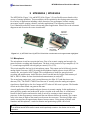
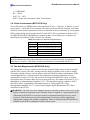
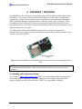
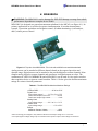
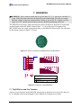
The MTS300CA (Figure 3-1a) and MTS310CA (Figure 3-1b) are flexible sensor boards with a
variety of sensing modalities. These modalities can be exploited in developing sensor networks
for a variety of applications including vehicle detection, low-performance seismic sensing,
movement, acoustic ranging, robotics, and other applications. The following section of the
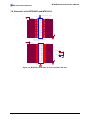
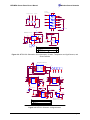
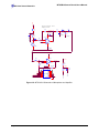
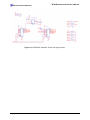
User’s Manual describes the sensor circuits and general application. Please refer to the schematic
diagram at end of section for exact circuit details.
Honeywell
HMC1002
Magnetometer
(a)
(b)
Analog Devices
ADXL202JE
Accelerometer
Figure 3-1. (a) MTS300CA and (b) MTS310CA with the accelerometer and magnetometer highlighted
3.1 Microphone
The microphone circuit has two principal uses: First is for acoustic ranging and second is for
general acoustic recording and measurement. The basic circuit consists of a pre-amplifier (U1A1), second-stage amplified with a digital-pot control (U1A, PT2).
This circuit amplifies the low-level microphone output. This output can be fed directly into the
analog-digital converter (ADC2) by using the Microphone Output selector circuit (MX1) to
connect mic_out signal to ADC2 signal. This configuration is useful for general acoustic
recording and measurement. Audio files have been recorded into the Logger Flash memory of
MICA, MICA2 Motes for later download and entertainment (or analysis!).
The second stage output (mic_out) is routed thru an active filter (U2) and then into a tone
detector (TD1). The LM567 CMOS Tone Detector IC actually turns the analog microphone
signal into a digital high or low level output at INT3 when a 4 kHz tone is present. The Sounder
circuit on the sensor board can generate this tone.
A novel application of the sounder and tone detector is acoustic ranging. In this application, a
mote pulses the sounder and sends an RF packet via radio at the same time. A second mote
listens for the RF packet and notes the time of arrival by resetting a timer/counter on its
processor. It then increments a counter until the tone detector detects the sounder. The counter
value is the time-of-flight of the sound wave between the two motes. The time-of-flight value
can be converted into an approximate distance between motes. Using groups of Motes with
Sounders and Microphones, a crude localization and positioning system can be built
; NOTE: Motes are designed for power efficiency. Hence all the sensors are disconnected from power
on the MTS300 and MTS310 sensor boards unless specifically turned on. See Section 3.6 for more
information.
Page 8
Doc. # 7430-0020-03 Rev.A