1
MTS/MDA Sensor Board User’s Manual
Wireless Sensor Networks
6 MDA300CA
0 WARNING: The MDA300CA can be damaged by ESD. ESD damage can range from subtle
performance degradation to complete device failure.
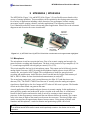
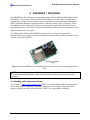
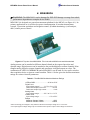
MDA300CA is designed as a general measurement platform for the MICA2 (see Figure 6-1). Its
primary applications are a) wireless low-power instrumentation, b) weather measurement
systems, c) precision agriculture and irrigation control, d) habitat monitoring, e) soil analysis,
and f) remote process control.
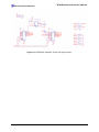
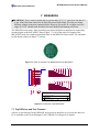
Figure 6-1. Top view of an MDA300CA. This is the side a MICA2 mote would be attached.
Analog sensors can be attached to different channels based on the expected precision and
dynamic range. Digital sensors can be attached to the provided digital or counter channels. Mote
samples analog, digital or counter channels and can actuate via digital outputs or relays. The
combination of a MICA2 (MPR400CB) and a MDA300CA can be used as a low-power wireless
data acquisition device or process control machine. Table 6-1 below gives the absolute maximum
ratings for various electrical parameters.
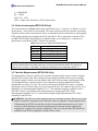
Table 6-1. The MDA300CAs Absolute Maximum Ratings
+VDD to GND*..............................–0.3V to +5.5V
Digital Lines:
Input voltage range**..…….-0.5 V to VDD+ 0.5 V
Continuous output low current…..……….50 mA
Continuous output high current………..…–4 mA
Analog Lines:
Input voltage range.………-0.2 V to VCC + 0.5 V
Counter Line:
Input voltage range ………………….0 V to 5.5V
Relays:
Maximum Contact Voltage……………..….100V
Maximum Contact Current…..…………..150mA
*Users are strongly encouraged to stay within the MICA2 nominal input voltage of 2.7 to 3.3 VDC
**The input negative-voltage ratings may be exceeded if the input and output current ratings are observed.
Doc. # 7430-0020-03 Rev.A
Page 23