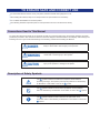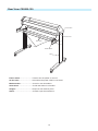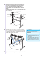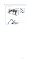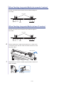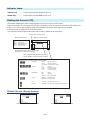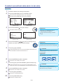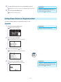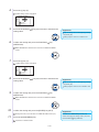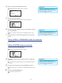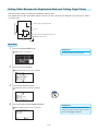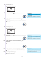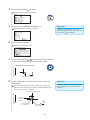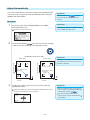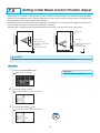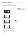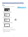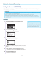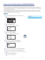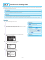
1
CE6000 SERIES
CUTTING PLOTTER
USER’S MANUAL
MANUAL NO.CE6000U-UM-152
TO ENSURE SAFE AND CORRECT USE
• To ensure the safe and correct use of your plotter, read this manual thoroughly prior to use.
• After reading this manual, keep it in a handy location for quick reference as necessary.
• Do not allow small children to touch the plotter.
• The following describes important points for safe operation. Be sure to observe them strictly.
Conventions Used in This Manual
To ensure the safe and accurate use of the plotter as well as to prevent human injury and property damage, the safety
precautions provided in this manual are ranked in the three categories described below. Their display and meaning is as
following. Be sure to gain a full understanding of the meaning of them before reading the Manual.
This category provides information that, if ignored, is highly
likely to cause fatal or serious injury to the operator.
DANGER
WARNING
This category provides information that, if ignored, is likely to
cause fatal or serious injury to the operator.
This category provides information that, if ignored, could cause
injury to the operator or damage to the plotter.
CAUTION
Description of Safety Symbols
The
symbol indicates information that requires careful attention
(including warnings). The specific point requiring attention is described by
an illustration or text within or next to the
symbol.
The
symbol indicates an action that is prohibited. Such prohibited
action is described by an illustration or text within or next to the
symbol.
The
symbol indicates an action that must be performed. Such
imperative action is described by an illustration or text within or next to the
symbol.
Safety Precautions
WARNING
Be sure to ground the earth terminal.
Do not touch the rollers or moving parts such as the
carriage while cutting or plotting is in progress.
•
Such action may result in injury.
f the plotter is not grounded, the operator could suffer an
•Ielectric
shock in the event of current leakage.
No touching
Ground the Plotter
Keep your hands, hair, etc., away from the rollers or
moving parts such as the carriage even if the plotter is
stopped, as it may suddenly start moving when data is
received.
Do not disassemble, repair, or remodel the plotter.
uch action may cause electric shock or a fire hazard due to
•Scurrent
leakage.
C
ontact
with the high-voltage parts within the plotter may
•cause electric
shock.
f the plotter requires repairs, contact your sales
•Irepresentative
or nearest Graphtec vendor.
•Such action may result in injury.
No disassembly
No touching
Do not connect the plotter to a non-rated power
supply.
Do not use the plotter in a location where it will be
exposed to water, rain, or snow.
uch action may cause electric shock or a fire hazard due to
•Scurrent
leakage.
uch action may cause electric shock or a fire hazard due to
•Scurrent
leakage.
Avoid water
Prohibited
If the plotter generates smoke, overheats, emits a
strange odor, or otherwise functions abnormally, do
not continue using it. Turn off the power and unplug
the power cord from the electrical socket.
Beware of
electrical shock
Do not allow dust or metal scraps to adhere to the
power plug.
uch action may cause electric shock or a fire hazard due to
•Scurrent
leakage.
se of the plotter in such a condition may result in a fire
•Uhazard
or electric shock.
A
fter
confirming
smoke is no longer being emitted,
•contact your salesthatrepresentative
or nearest Graphtec vendor
for repairs.
ever attempt to perform repairs yourself.
•NRepair
work by inexperienced
personnel is extremely dangerous.
Prohibited
Prohibited
ii
Beware of
electrical shock
Safety Precautions
WARNING
Do not use the power cord if it is damaged.
•
•
Be careful when handling the cutter blade.
•Touching the blade with your bare hand may cause injury.
•Do not touch the cutter blade while cutting is in progress.
Use of a damaged cord may result in electric shock or a fire
hazard due to current leakage.
Replace the power cord with a new one.
Unplug the power
cord from the socket
No touching
CAUTION
Do not use or store the plotter in a location exposed
to direct sunlight or the direct draft of an air
conditioner or heater.
Do not use the plotter in an excessively dusty or
humid location.
•Such locations may impair the performance of the plotter.
uch locations may impair the
•Sperformance
of the plotter.
Prohibited
Prohibited
Do not place any receptacle containing water or
other fluid on top of the plotter.
Do not use the plotter in a location subject to
excessive mechanical vibration or electrical noise.
falling inside the plotter may cause electric shock or a
•Ffireluidhazard
due to current leakage.
Avoid water
•Such locations may impair the performance of the plotter.
Beware of
electrical shock
Prohibited
When disconnecting the power cord or interface
cable, do not pull on the cord/cable.
If water or foreign matter enters the plotter,
discontinue use. Turn off the power and unplug the
power cord from the electrical socket.
uch action will damage the cord/cable, resulting in a fire
•Shazard
or electric shock.
se of a damaged cord may result in electric shock or a fire
•Uhazard
due to current leakage.
your sales representative or nearest Graphtec vendor
•Contact
for repairs.
Unplug the power
cord from the socket
Prohibited
iii
Safety Precautions
CAUTION
Do not attempt to lubricate the cutting-plotter
mechanisms.
Do not clean the plotter using volatile solvents such
as thinner or benzene.
•Such action may cause it to break down.
•Such action may impair its performance.
Prohibited
Prohibited
Provide sufficient space around the plotter so that
it does not strike any objects in its vicinity during
cutting.
When using indoor lighting such as fluorescent or
other electrical lamps, provide a distance of at least
one meter between the plotter and the light source.
•Such contact may cause misalignment in cutting or plotting.
proximity of such a light source may cause the sensor
•Ctolose
malfunction and prevent proper size detection of the media.
No touching
When using the cutter, take care not to extend the
blade more than necessary.
Move the tool carriage slowly when moving it
manually in order to load the medium or for other
reasons.
n overly extended blade will damage the cutting mat and
•Aadversely
affect the cutting quality.
•Moving it quickly may damage the plotter.
Do not place the plotter on an incline, areas subject
to many vibrations, or other unstable locations.
Do not place magnetic cards, diskettes or similar
items in the vicinity of the tool carriage.
•If the plotter falls, it may sustain damage.
he magnetic force may destroy the data on the magnetic
•Tcards
or diskettes.
Prohibited
Prohibited
Run a test cut when cutting media with unknown
condition settings.
unning a cut operation with incorrect setting values may
•Rcause
a large overload to the blades and device or a system
breakdown.
iv
Preface
Thank you for choosing a Graphtec CE6000 Series plotter. The CE6000 Series plotters employ a digital
servo drive system to achieve high-speed and high-precision cutting. In addition to cutting marking film and
other media, an CE6000 series plotter can also be used as a pen plotter. To ensure high cutting quality and
optimal productivity, be sure to read this User's Manual thoroughly prior to use.
This product is manufactured and sold pursuant to a license under Gerber Scientific International, Inc.'s U.S.
Patent No. 5,537,135 and its foreign counterparts.
Notes on this Manual
(1) No part of this publication may be reproduced, stored in a retrieval system, or transmitted, in any form or
by any means, without the prior written permission of Graphtec Corporation.
(2) The product specifications and other information in this manual are subject to change without notice.
(3) While every effort has been made to provide complete and accurate information, please contact your
sales representative or nearest Graphtec vendor if you find any unclear or erroneous information or wish
to make other comments or suggestions.
(4) Not with standing the stipulations in the preceding paragraph, Graphtec Corporation assumes no liability
for damages resulting from either the use of the information contained herein or the use of the product.
Registered Trademarks
All names of companies, brands, logotypes, and products appearing in this manual are the trademarks or
registered trademarks of their respective companies.
Copyright
This User's Manual is copyrighted by Graphtec Corporation.
Special Precautions on Handling Blades
Sharp cutter blades are used with this plotter. Handle the cutter blades and holders with care to prevent
bodily injury.
Cutter Blades
Cutter blades are very sharp. While handling a cutter blade or cutter pen, be careful to avoid cutting your
fingers or other parts of your body. Promptly return used blades to the cutter case provided.
Blade tip
When the case is completely filled, discard the used blades together with the case.
Cutter Pens
The tip consists of a sharp blade. Be sure not to extend it too far. Moreover, when you are not using the
cutter pen, make sure that the blade is fully retracted.
Cutter blade
After Mounting the Cutter Pen
After the power has been turned on, and during operation, do not touch the pen tip. It is dangerous.
II
After Turning on the Plotter
During the course of turning on the plotter, be sure to observe the following precautions. The tool carriage
and loaded media may suddenly move during the cutting operation, immediately afterward and when setting
the plotter's functions. Keep hands, hair, clothing and other objects out of the vicinity of the tool carriage, grit
rollers and loaded media. To prevent operator injury and poor cutting results, be careful not to allow hands,
hair, clothing or other foreign objects to become entangled with the tool carriage or loaded media while the
plotter is operating.
Machine Caution Label
The machine's Caution Label is located on the top cover. Be sure to observe all the cautions on the label.
Notes on the Stand
Be sure to use only the stand designed for the CE6000 Series with your CE6000 Series plotter. The use of a
different stand may cause a plotter malfunction or bodily injury.
III
About the words and phrases in this text
•In this instruction manual, the word "plot" refers to operating the machine and using either the plotting pen
or the cutter pen to cut.
•In this instruction manual, the word "media" refers to paper, roll media, sheet media, or marking film.
Prior to use
•Be sure to read the attached TO ENSURE SAFE AND CORRECT USE prior to use. Otherwise, it may
cause an unexpected accident or fire.
Attention of the curled media
•The media jamming occurs when strongly curling media is used.
•Please use uncurling media or remove the curling from the media before installing such kind of media.
WARNING
The United States Federal Communications Commission has specified that the following notice must be
brought to the attention of users of this product.
FEDERAL COMMUNICATIONS COMMISSION RADIO FREQUENCY INTERFERENCE STATEMENT
NOTE: This equipment has been tested and found to comply with the limits for a Class A digital device,
pursuant to part 15 of the FCC Rules. These limits are designed to provide reasonable protection against
harmful interference when the equipment is operated in a commercial environment.
This equipment generates, uses, and can radiate radio frequency energy and, if not installed and used in
accordance with the instruction manual, may cause harmful interference to radio communications. Operation
of this equipment in a residential area is likely to cause harmful interference in which case the user will be
required to correct the interference at his own expense.
USE SHIELDED CABLES
To comply with FCC Class A requirements, all external data interface cables and connectors must be
properly shielded and grounded. Proper cables and connectors are available from GRAPHTEC’s authorized
dealers or manufacturers of computers or peripherals. GRAPHTEC is not responsible for any interference
caused by using cables and connectors other than those recommended or by unauthorized changes or
modifications to this equipment. Unauthorized changes or modifications could void the user’s authority to
operate the equipment.
IV
Selecting a Power Cable
Be sure to refer to the following tables if you wish to use a cable other than the one supplied as an
accessory.
Table 1. 100 V to 120 V Power Supply Voltage Range
Plug Configuration
Plug Type
Supply Voltage
Selector Settings
Reference
Standards
100/120 V
ANSI C73.11
NEMA 5-15
UL498/817/62
CSA22.2
NO.42/21/49
Supply Voltage
Selector Settings
Reference
Standards
North America
125 V
10 A
Power Cable
UL Listed
Type SJT
No.18AWG × 3
300 V, 10 A
Table 2. 200 V to 240 V Power Supply Voltage Range
Plug Configuration
Plug Type
Europe
250 V
10 A
Power Cable
200 V
CEE(7)VII
IEC320
CEE13
TYPE: H05VV-F
3 × 1.0 mm2
UK
250 V
5A
200 V
BS1363
BS4491
BS6500
TYPE: H05VV-F
3 × 1.0 mm2
Australia
250 V
10 A
200 V
AS3112
AS3109
AS3191
TYPE: OD3CFC
3 × 1.0 mm2
North America
250 V
15 A
200 V
ANSI C73.20
NEMA 6-15
UL 198.6
Switzerland
250 V
6A
200 V
SEV1011
SEV1004
SEV1012
TYPE: H05VV-F
3 × 0.75 mm2
200 V
GB15934
GB2099.1
GB1002
GB/T 5023.5
TYPE: H05VV-F
3 × 1.0 mm2
China
250 V
6A
UL Listed
Type SJT
No.18AWG × 3
300 V, 10 A
CONTENTS
TO ENSURE SAFE AND CORRECT USE . . . . . . . . . . . . . . . . . . . . . . . . . . . . . . . . . . . . . . . . . . . i
Preface . . . . . . . . . . . . . . . . . . . . . . . . . . . . . . . . . . . . . . . . . . . . . . . . . . . . . . . . . . . . . . . . . . . . . . I
Special Precautions on Handling Blades . . . . . . . . . . . . . . . . . . . . . . . . . . . . . . . . . . . . . . . . . . . II
After Turning on the Plotter . . . . . . . . . . . . . . . . . . . . . . . . . . . . . . . . . . . . . . . . . . . . . . . . . . . . . . III
Machine Caution Label . . . . . . . . . . . . . . . . . . . . . . . . . . . . . . . . . . . . . . . . . . . . . . . . . . . . . . . . . III
Notes on the Stand . . . . . . . . . . . . . . . . . . . . . . . . . . . . . . . . . . . . . . . . . . . . . . . . . . . . . . . . . . . . III
About the words and phrases in this text . . . . . . . . . . . . . . . . . . . . . . . . . . . . . . . . . . . . . . . . . . IV
Prior to use . . . . . . . . . . . . . . . . . . . . . . . . . . . . . . . . . . . . . . . . . . . . . . . . . . . . . . . . . . . . . . . . . IV
Attention of the curled media . . . . . . . . . . . . . . . . . . . . . . . . . . . . . . . . . . . . . . . . . . . . . . . . . . . IV
Selecting a Power Cable . . . . . . . . . . . . . . . . . . . . . . . . . . . . . . . . . . . . . . . . . . . . . . . . . . . . . . . . V
Chapter 1 Product Summary
1.1
1.2
1.3
1.4
Checking the Accessories . . . . . . . . . . . . . . . . . . . . . . . . . . . . . . . . . . . . . . . . . . . . . . . 1-2
Nomenclature . . . . . . . . . . . . . . . . . . . . . . . . . . . . . . . . . . . . . . . . . . . . . . . . . . . . . . . . 1-3
Front View: CE6000-40 . . . . . . . . . . . . . . . . . . . . . . . . . . . . . . . . . . . . . . . . . . . . . . . 1-3
Rear View: CE6000-40 . . . . . . . . . . . . . . . . . . . . . . . . . . . . . . . . . . . . . . . . . . . . . . . . 1-4
Front View: CE6000-60 . . . . . . . . . . . . . . . . . . . . . . . . . . . . . . . . . . . . . . . . . . . . . . . 1-5
Rear View: CE6000-60 . . . . . . . . . . . . . . . . . . . . . . . . . . . . . . . . . . . . . . . . . . . . . . . 1-6
Front View: CE6000-120 . . . . . . . . . . . . . . . . . . . . . . . . . . . . . . . . . . . . . . . . . . . . . . . . 1-7
Rear View: CE6000-120 . . . . . . . . . . . . . . . . . . . . . . . . . . . . . . . . . . . . . . . . . . . . . . . 1-8
Assembling . . . . . . . . . . . . . . . . . . . . . . . . . . . . . . . . . . . . . . . . . . . . . . . . . . . . . . . . . . 1-9
Mounting the Roll-medium tray . . . . . . . . . . . . . . . . . . . . . . . . . . . . . . . . . . . . . . . . . 1-14
Mounting the Stock shafts . . . . . . . . . . . . . . . . . . . . . . . . . . . . . . . . . . . . . . . . . . . . . 1-14
Connecting to the Computer . . . . . . . . . . . . . . . . . . . . . . . . . . . . . . . . . . . . . . . . . . . . . 1-16
Chapter 2: Preparing to Cut
2.1
2.2
2.3
2.4
2.5
2.6
2.7
Preparation of Cutter Plunger . . . . . . . . . . . . . . . . . . . . . . . . . . . . . . . . . . . . . . . . . . . . 2-2
Cutter Plunger Nomenclature . . . . . . . . . . . . . . . . . . . . . . . . . . . . . . . . . . . . . . . . . . . 2-2
Structure of Cutter Plunger . . . . . . . . . . . . . . . . . . . . . . . . . . . . . . . . . . . . . . . . . . . . . 2-2
Blade Application and Features . . . . . . . . . . . . . . . . . . . . . . . . . . . . . . . . . . . . . . . . . 2-3
Attaching a Tool . . . . . . . . . . . . . . . . . . . . . . . . . . . . . . . . . . . . . . . . . . . . . . . . . . . . . . 2-4
Attaching a Tool . . . . . . . . . . . . . . . . . . . . . . . . . . . . . . . . . . . . . . . . . . . . . . . . . . . . . 2-4
Removing the tool . . . . . . . . . . . . . . . . . . . . . . . . . . . . . . . . . . . . . . . . . . . . . . . . . . . 2-5
Loading Media (Paper or Marking Film) . . . . . . . . . . . . . . . . . . . . . . . . . . . . . . . . . . . . 2-6
Loading Roll Media (CE6000-40) . . . . . . . . . . . . . . . . . . . . . . . . . . . . . . . . . . . . . . . . 2-6
Loading Roll Media (CE6000-60/120) . . . . . . . . . . . . . . . . . . . . . . . . . . . . . . . . . . . . 2-9
Loading Sheet Media (CE6000-40/60) . . . . . . . . . . . . . . . . . . . . . . . . . . . . . . . . . . . . 2-14
Loading Sheet Media (CE6000-120) . . . . . . . . . . . . . . . . . . . . . . . . . . . . . . . . . . . . . 2-16
Carrier Sheet (for Affixing Media for Cutting) . . . . . . . . . . . . . . . . . . . . . . . . . . . . . . . 2-19
Aligning the Push Rollers . . . . . . . . . . . . . . . . . . . . . . . . . . . . . . . . . . . . . . . . . . . . . . 2-22
Aligning the Push Roller . . . . . . . . . . . . . . . . . . . . . . . . . . . . . . . . . . . . . . . . . . . . . . 2-22
Changing the Hold-down Force . . . . . . . . . . . . . . . . . . . . . . . . . . . . . . . . . . . . . . . . 2-24
About the Default Screen . . . . . . . . . . . . . . . . . . . . . . . . . . . . . . . . . . . . . . . . . . . . . . 2-25
Connecting to the Power . . . . . . . . . . . . . . . . . . . . . . . . . . . . . . . . . . . . . . . . . . . . . . . 2-26
How to Use Control Panel . . . . . . . . . . . . . . . . . . . . . . . . . . . . . . . . . . . . . . . . . . . . . . 2-27
Control Keys . . . . . . . . . . . . . . . . . . . . . . . . . . . . . . . . . . . . . . . . . . . . . . . . . . . . . . . 2-27
Menu Keys . . . . . . . . . . . . . . . . . . . . . . . . . . . . . . . . . . . . . . . . . . . . . . . . . . . . . . . . 2-27
Indicator Lamp . . . . . . . . . . . . . . . . . . . . . . . . . . . . . . . . . . . . . . . . . . . . . . . . . . . . . 2-28
C-1
2.8
2.9
2.10
2.11
2.12
Reading the Screen (LCD) . . . . . . . . . . . . . . . . . . . . . . . . . . . . . . . . . . . . . . . . . . . 2-28
Contents of Operation from Menu Screen . . . . . . . . . . . . . . . . . . . . . . . . . . . . . . . . 2-30
Contents of Operation from [COND/TEST] Key . . . . . . . . . . . . . . . . . . . . . . . . . . . . 2-31
Setting Feeding Method . . . . . . . . . . . . . . . . . . . . . . . . . . . . . . . . . . . . . . . . . . . . . . . 2-32
Pre Feed of Media (Paper or Marking Film) . . . . . . . . . . . . . . . . . . . . . . . . . . . . . . . . 2-34
Selecting Tool Condition . . . . . . . . . . . . . . . . . . . . . . . . . . . . . . . . . . . . . . . . . . . . . . . 2-35
Setting the Tool Condition . . . . . . . . . . . . . . . . . . . . . . . . . . . . . . . . . . . . . . . . . . . . 2-37
Setting the Speed and Force (Simple mode) . . . . . . . . . . . . . . . . . . . . . . . . . . . . . . 2-39
Setting the Tool . . . . . . . . . . . . . . . . . . . . . . . . . . . . . . . . . . . . . . . . . . . . . . . . . . . . 2-41
Setting the Speed . . . . . . . . . . . . . . . . . . . . . . . . . . . . . . . . . . . . . . . . . . . . . . . . . . . 2-43
Setting the Force . . . . . . . . . . . . . . . . . . . . . . . . . . . . . . . . . . . . . . . . . . . . . . . . . . . 2-44
Setting the Acceleration . . . . . . . . . . . . . . . . . . . . . . . . . . . . . . . . . . . . . . . . . . . . . . 2-45
Adjust the Blade Length Manually . . . . . . . . . . . . . . . . . . . . . . . . . . . . . . . . . . . . . . 2-47
Running Cutting Tests . . . . . . . . . . . . . . . . . . . . . . . . . . . . . . . . . . . . . . . . . . . . . . . . . 2-48
Cutting Test . . . . . . . . . . . . . . . . . . . . . . . . . . . . . . . . . . . . . . . . . . . . . . . . . . . . . . . 2-48
Confirm the Results of the Cutting Test . . . . . . . . . . . . . . . . . . . . . . . . . . . . . . . . . . 2-50
Adjust the Blade Length (Automatic Height Adjust) . . . . . . . . . . . . . . . . . . . . . . . . . 2-51
About Simple mode . . . . . . . . . . . . . . . . . . . . . . . . . . . . . . . . . . . . . . . . . . . . . . . . . . . 2-54
Chapter 3: Basic Operations
3.1
3.2
3.3
3.4
3.5
Raise or Lower the Tool . . . . . . . . . . . . . . . . . . . . . . . . . . . . . . . . . . . . . . . . . . . . . . . . 3-2
Move the Tool Carriage and Media . . . . . . . . . . . . . . . . . . . . . . . . . . . . . . . . . . . . . . . . 3-3
Move in Steps Manually . . . . . . . . . . . . . . . . . . . . . . . . . . . . . . . . . . . . . . . . . . . . . . . 3-3
Continuously Move Manually . . . . . . . . . . . . . . . . . . . . . . . . . . . . . . . . . . . . . . . . . . . 3-3
Setting of Step Movement Distance . . . . . . . . . . . . . . . . . . . . . . . . . . . . . . . . . . . . . . 3-4
Move Away the Tool Carriage . . . . . . . . . . . . . . . . . . . . . . . . . . . . . . . . . . . . . . . . . . . 3-5
Change the Cutting Condition (Condition No.) . . . . . . . . . . . . . . . . . . . . . . . . . . . . . . 3-6
Reset (Revert to the initial state when the power was turned on.) . . . . . . . . . . . . . . . 3-6
Setting the Origin Point . . . . . . . . . . . . . . . . . . . . . . . . . . . . . . . . . . . . . . . . . . . . . . . . . 3-7
When Coordinate Axes Rotation are Set . . . . . . . . . . . . . . . . . . . . . . . . . . . . . . . . . . 3-8
When Coordinate Axes are Rotated After Origin Point is Set . . . . . . . . . . . . . . . . . . 3-8
Setting Origin Point When HP-GL is Set . . . . . . . . . . . . . . . . . . . . . . . . . . . . . . . . . . 3-9
Setting the Cutting Direction . . . . . . . . . . . . . . . . . . . . . . . . . . . . . . . . . . . . . . . . . . . . . 3-10
Stop Cutting . . . . . . . . . . . . . . . . . . . . . . . . . . . . . . . . . . . . . . . . . . . . . . . . . . . . . . . . . 3-12
Pause and Resume Cutting . . . . . . . . . . . . . . . . . . . . . . . . . . . . . . . . . . . . . . . . . . . . 3-12
Stop Cutting . . . . . . . . . . . . . . . . . . . . . . . . . . . . . . . . . . . . . . . . . . . . . . . . . . . . . . . . 3-13
Chapter 4: Convenient Functions
4.1
4.2
4.3
Settings for Cutting . . . . . . . . . . . . . . . . . . . . . . . . . . . . . . . . . . . . . . . . . . . . . . . . . . . . 4-2
Setting Cutting Area . . . . . . . . . . . . . . . . . . . . . . . . . . . . . . . . . . . . . . . . . . . . . . . . . . 4-2
Setting Cutting Width (EXPAND) . . . . . . . . . . . . . . . . . . . . . . . . . . . . . . . . . . . . . . . . 4-4
Setting Length of the Page . . . . . . . . . . . . . . . . . . . . . . . . . . . . . . . . . . . . . . . . . . . . . 4-5
Setting Mirror . . . . . . . . . . . . . . . . . . . . . . . . . . . . . . . . . . . . . . . . . . . . . . . . . . . . . . . 4-7
Set the enlarge/shrink scale (Scale) . . . . . . . . . . . . . . . . . . . . . . . . . . . . . . . . . . . . . . 4-8
Copy (Duplicate Cutting) . . . . . . . . . . . . . . . . . . . . . . . . . . . . . . . . . . . . . . . . . . . . . . . . 4-10
Panel Cutting . . . . . . . . . . . . . . . . . . . . . . . . . . . . . . . . . . . . . . . . . . . . . . . . . . . . . . . . . 4-15
Chapter 5: ARMS (Advanced Registration Mark Sensing System)
5.1
Outline of ARMS . . . . . . . . . . . . . . . . . . . . . . . . . . . . . . . . . . . . . . . . . . . . . . . . . . . . . . 5-2
Shape (Pattern) of the Registration Mark . . . . . . . . . . . . . . . . . . . . . . . . . . . . . . . . . . 5-2
Scan Range Necessary to Detect the Registration Mark . . . . . . . . . . . . . . . . . . . . . . 5-3
C-2
5.2
5.3
Positioning of the Media and the Registration Mark . . . . . . . . . . . . . . . . . . . . . . . . . . 5-4
Position of the Origin Point and the Registration Mark . . . . . . . . . . . . . . . . . . . . . . . . 5-5
Cutting area when adjusting the regisitaration mark . . . . . . . . . . . . . . . . . . . . . . . . . 5-6
Automatic detection of registration mark position . . . . . . . . . . . . . . . . . . . . . . . . . . . . 5-6
Media That Registration Mark Cannot be Detected . . . . . . . . . . . . . . . . . . . . . . . . . . 5-6
Setting and Adjustment of ARMS . . . . . . . . . . . . . . . . . . . . . . . . . . . . . . . . . . . . . . . . . 5-7
Setting MARK SCAN Mode and Numbers . . . . . . . . . . . . . . . . . . . . . . . . . . . . . . . . . 5-7
Setting Shape (Pattern) of Registration Mark . . . . . . . . . . . . . . . . . . . . . . . . . . . . . . . 5-11
Setting Registration Mark Size . . . . . . . . . . . . . . . . . . . . . . . . . . . . . . . . . . . . . . . . . . 5-12
Setting Mark Distance . . . . . . . . . . . . . . . . . . . . . . . . . . . . . . . . . . . . . . . . . . . . . . . . 5-14
Setting Distance Adjustment Between the Registration Mark . . . . . . . . . . . . . . . . . 5-16
Setting Offset Between the Registration Mark and Cutting Origin Points . . . . . . . . 5-18
Adjusting the Sensor Level . . . . . . . . . . . . . . . . . . . . . . . . . . . . . . . . . . . . . . . . . . . . 5-20
Manually Adjusting the Sensor Level (Threshold Value) . . . . . . . . . . . . . . . . . . . . . 5-22
Test the Registration Mark Sensor . . . . . . . . . . . . . . . . . . . . . . . . . . . . . . . . . . . . . . 5-24
Setting Speed of the Registration Mark Scan . . . . . . . . . . . . . . . . . . . . . . . . . . . . . 5-26
Adjusting for the Registration Mark Scan Position . . . . . . . . . . . . . . . . . . . . . . . . . . 5-27
Detect the Registration Mark for Adjustment on the Media and Enter the Value . . . 5-30
Setting the registration mark automatic detection . . . . . . . . . . . . . . . . . . . . . . . . . . 5-33
Setting the Position Using ARMS . . . . . . . . . . . . . . . . . . . . . . . . . . . . . . . . . . . . . . . . 5-35
Adjust with 2POINTS . . . . . . . . . . . . . . . . . . . . . . . . . . . . . . . . . . . . . . . . . . . . . . . . 5-35
Adjust with 3POINTS . . . . . . . . . . . . . . . . . . . . . . . . . . . . . . . . . . . . . . . . . . . . . . . . 5-37
Adjust with 4POINTS . . . . . . . . . . . . . . . . . . . . . . . . . . . . . . . . . . . . . . . . . . . . . . . . 5-38
Adjust Automatically . . . . . . . . . . . . . . . . . . . . . . . . . . . . . . . . . . . . . . . . . . . . . . . . . 5-40
Adjust Manually . . . . . . . . . . . . . . . . . . . . . . . . . . . . . . . . . . . . . . . . . . . . . . . . . . . . 5-41
Chapter 6: Manual Position Adjust
6.1
6.2
Outline of Manual Position Adjust . . . . . . . . . . . . . . . . . . . . . . . . . . . . . . . . . . . . . . . . . 6-2
Setting of Mark Scan Mode and Number of Adjustment Marks . . . . . . . . . . . . . . . . . 6-2
Manual Position Adjust . . . . . . . . . . . . . . . . . . . . . . . . . . . . . . . . . . . . . . . . . . . . . . . . . 6-3
Chapter 7: Setting Regarding Cutting Quality
7.2
7.3
7.4
7.5
7.6
7.7
To cut the corner of thick media sharply . . . . . . . . . . . . . . . . . . . . . . . . . . . . . . . . . . . . . 7-2
Outline of Tangential Mode . . . . . . . . . . . . . . . . . . . . . . . . . . . . . . . . . . . . . . . . . . . . . 7-2
Setting the Tangential Mode . . . . . . . . . . . . . . . . . . . . . . . . . . . . . . . . . . . . . . . . . . . . 7-3
Setting Length of the Overcut . . . . . . . . . . . . . . . . . . . . . . . . . . . . . . . . . . . . . . . . . . . 7-4
Setting of the Initial Down Force . . . . . . . . . . . . . . . . . . . . . . . . . . . . . . . . . . . . . . . . 7-6
Setting the Step Pass . . . . . . . . . . . . . . . . . . . . . . . . . . . . . . . . . . . . . . . . . . . . . . . . . . . 7-7
Setting the Offset Angle . . . . . . . . . . . . . . . . . . . . . . . . . . . . . . . . . . . . . . . . . . . . . . . . 7-8
Setting the Distance Adjust . . . . . . . . . . . . . . . . . . . . . . . . . . . . . . . . . . . . . . . . . . . . . . 7-9
Setting Initial Blade Control Position Adjust . . . . . . . . . . . . . . . . . . . . . . . . . . . . . . . . . 7-11
Settings for OFFSET FORCE . . . . . . . . . . . . . . . . . . . . . . . . . . . . . . . . . . . . . . . . . . . . 7-13
Setting Paper-Weight . . . . . . . . . . . . . . . . . . . . . . . . . . . . . . . . . . . . . . . . . . . . . . . . . . 7-14
8.1
8.2
8.3
8.4
8.5
8.6
Sorting the Cutting Data . . . . . . . . . . . . . . . . . . . . . . . . . . . . . . . . . . . . . . . . . . . . . . . . 8-2
Perform Automatic Pre Feed When Cut Data is Received . . . . . . . . . . . . . . . . . . . . . . 8-4
Perform Automatic Pre Feed When Media is Set (Initial Feed) . . . . . . . . . . . . . . . . . . . 8-6
Setting Feed Speed for Pre Feed . . . . . . . . . . . . . . . . . . . . . . . . . . . . . . . . . . . . . . . . . 8-7
Setting the Tool Up Speed . . . . . . . . . . . . . . . . . . . . . . . . . . . . . . . . . . . . . . . . . . . . . . 8-9
Setting the Tool Up Move . . . . . . . . . . . . . . . . . . . . . . . . . . . . . . . . . . . . . . . . . . . . . . . 8-11
7.1
Chapter 8: Settings Regarding Cutting Time
C-3
Chapter 9: Setting Regarding Interface
9.1
Setting Interface . . . . . . . . . . . . . . . . . . . . . . . . . . . . . . . . . . . . . . . . . . . . . . . . . . . . . . 9-2
USB Interface . . . . . . . . . . . . . . . . . . . . . . . . . . . . . . . . . . . . . . . . . . . . . . . . . . . . . . . 9-2
RS-232C Interface . . . . . . . . . . . . . . . . . . . . . . . . . . . . . . . . . . . . . . . . . . . . . . . . . . . 9-2
Interface Setting Menu . . . . . . . . . . . . . . . . . . . . . . . . . . . . . . . . . . . . . . . . . . . . . . . . 9-2
Connecting with RS-232C . . . . . . . . . . . . . . . . . . . . . . . . . . . . . . . . . . . . . . . . . . . . . 9-3
Chapter 10: Settings Regarding Operation Environment
Related to Menu Display . . . . . . . . . . . . . . . . . . . . . . . . . . . . . . . . . . . . . . . . . . . . . 10-2
Related to Sensor . . . . . . . . . . . . . . . . . . . . . . . . . . . . . . . . . . . . . . . . . . . . . . . . . . . 10-4
Related to Plotter Environment . . . . . . . . . . . . . . . . . . . . . . . . . . . . . . . . . . . . . . . . . 10-6
Chapter 11: Settings of Controls from Computer
Related to Command Processing . . . . . . . . . . . . . . . . . . . . . . . . . . . . . . . . . . . . . . . . 11-2
Related to GP-GL Command . . . . . . . . . . . . . . . . . . . . . . . . . . . . . . . . . . . . . . . . . . . 11-4
Related to HP-GL Command . . . . . . . . . . . . . . . . . . . . . . . . . . . . . . . . . . . . . . . . . . . 11-7
Chapter 12: Maintenance
12.1
12.2
12.3
12.4
Daily Maintenance . . . . . . . . . . . . . . . . . . . . . . . . . . . . . . . . . . . . . . . . . . . . . . . . . . . . 12-2
Daily Maintenance . . . . . . . . . . . . . . . . . . . . . . . . . . . . . . . . . . . . . . . . . . . . . . . . . . 12-2
Storing the Plotter . . . . . . . . . . . . . . . . . . . . . . . . . . . . . . . . . . . . . . . . . . . . . . . . . . . 12-2
Replacing Cutter Blade . . . . . . . . . . . . . . . . . . . . . . . . . . . . . . . . . . . . . . . . . . . . . . . . 12-3
Cleaning the Cutter Pen . . . . . . . . . . . . . . . . . . . . . . . . . . . . . . . . . . . . . . . . . . . . . . . 12-4
Cutter Plunger Exchange . . . . . . . . . . . . . . . . . . . . . . . . . . . . . . . . . . . . . . . . . . . . . . 12-5
Chapter 13: Troubleshooting
13.1
13.2
13.3
13.4
13.5
13.6
Troubleshooting . . . . . . . . . . . . . . . . . . . . . . . . . . . . . . . . . . . . . . . . . . . . . . . . . . . . . . 13-2
When the Plotter Does Not Operate After Turning the Power On . . . . . . . . . . . . . . 13-2
When It Does Not Work Right . . . . . . . . . . . . . . . . . . . . . . . . . . . . . . . . . . . . . . . . . 13-3
When the Cutting Result is Not Good . . . . . . . . . . . . . . . . . . . . . . . . . . . . . . . . . . . 13-5
Error Messages in GP-GL Command Mode . . . . . . . . . . . . . . . . . . . . . . . . . . . . . . 13-6
Error Messages in HP-GL Command Mode . . . . . . . . . . . . . . . . . . . . . . . . . . . . . . . 13-7
ARMS Error Messages . . . . . . . . . . . . . . . . . . . . . . . . . . . . . . . . . . . . . . . . . . . . . . . 13-9
Other Error Messages . . . . . . . . . . . . . . . . . . . . . . . . . . . . . . . . . . . . . . . . . . . . . . . 13-11
Caution Message . . . . . . . . . . . . . . . . . . . . . . . . . . . . . . . . . . . . . . . . . . . . . . . . . . . 13-13
Printing the Setting of the Plotter . . . . . . . . . . . . . . . . . . . . . . . . . . . . . . . . . . . . . . . . 13-14
Creating Test Pattern . . . . . . . . . . . . . . . . . . . . . . . . . . . . . . . . . . . . . . . . . . . . . . . . . 13-16
Creating CUTTING PRO . . . . . . . . . . . . . . . . . . . . . . . . . . . . . . . . . . . . . . . . . . . . . . . 13-18
Confirm the Cutting Data . . . . . . . . . . . . . . . . . . . . . . . . . . . . . . . . . . . . . . . . . . . . . . 13-20
Self Diagnostic Test . . . . . . . . . . . . . . . . . . . . . . . . . . . . . . . . . . . . . . . . . . . . . . . . . . 13-22
Reading the Error Message . . . . . . . . . . . . . . . . . . . . . . . . . . . . . . . . . . . . . . . . . . 13-23
Appendix
A.1
A.2
A.3
A.4
A.5
Main Specifications . . . . . . . . . . . . . . . . . . . . . . . . . . . . . . . . . . . . . . . . . . . . . . . . . . . . A-2
Options and Supplies . . . . . . . . . . . . . . . . . . . . . . . . . . . . . . . . . . . . . . . . . . . . . . . . . . A-3
External Dimensions . . . . . . . . . . . . . . . . . . . . . . . . . . . . . . . . . . . . . . . . . . . . . . . . . . . A-4
Menu Tree . . . . . . . . . . . . . . . . . . . . . . . . . . . . . . . . . . . . . . . . . . . . . . . . . . . . . . . . . . . A-7
Initial Setting . . . . . . . . . . . . . . . . . . . . . . . . . . . . . . . . . . . . . . . . . . . . . . . . . . . . . . . . A-13
INDEX . . . . . . . . . . . . . . . . . . . . . . . . . . . . . . . . . . . . . . . . . . . . . . . . . . . . . . . . . . . . . . . . . . . . . I-1
C-4
Chapter 1 Product Summary
This chapter explains how to connect this device your computer.
PRODUCT SUMMARY
1.1
1.2
1.3
1.4
Checking the Accessories
Nomenclature
Assembling
Connecting to the Computer
1-1
1.1
Checking the Accessories
Accessories
Item
Q'ty
Item
Q'ty
Power cable
1 pc
USB cable
1 pc
DVD
2 pcs
SETUP MANUAL,
TO ENSURE SAFE AND CORRECT USE
Cutter Blade Manual
1 of
each
Cutter holder (PHP33-CB09N-HS)
1 pc
Cutter blades
1 pc
Water-based fiber pen adapter (PHP31-FIBER)
1 set
Water-based fiber pen (KF700-BK [1P])
1 pc
1 pc
Carrier Sheet (CR09300-A3)
1 set
• Various software
• User's Manual (pdf)
* Plunger/Height adjustment tool.
Media Cutter
(CE6000-40 only).
*Other software data may be added later.
Dedicated Accessories
CE6000-40
Item
Roll-medium tray
Q'ty
1 set
CE6000-60
Item
Q'ty
Stand
1 set
or Roll-medium tray*
* The roll medium tray is standard accessories
for the CE6000-60 without stands.
1-2
CE6000-120
Stand
Item
Q'ty
1 set
1.2
Nomenclature
Front View: CE6000-40
Tool carriage
Control panel
Tool holder
Grit roller position guide
Media set lever
Cutting mat
USB interface connector
Cutting groove
Push roller
Media sensor
RS-232C interface connector
Grit roller
Control panel............................Used to access various plotter functions.
Push rollers..............................Rollers that push the media against the grit rollers.
Grit rollers.................................Metallic rollers with a file-like surface that feed the media back and forth.
Media sensors..........................The front sensor is used to sense the leading edge of the media. The rear
sensor is used to sense the trailing edge of the media.
Tool carriage.............................Moves the cutter-pen or plotting pen across the media during cutting or
plotting.
Tool holder................................Holds the cutter-pen or plotting pen and moves it up or down.
Grit roller position guide.........Stickers on the front of the Y rail and the rear side of the top cover that show
the position of each grit roller. Use these alignment marks as an aid in locating
the Push rollers.
Cutting mat...............................Cutter blade moved on this mat, preventing wears of the blade.
Cutting groove..........................Use this groove when using the media cutter.
Media set lever.........................Used to raise or lower the Push rollers during the loading or unloading of
media.
USB interface connector.........Used to connect the plotter to the computer with a USB interface cable.
RS-232C interface connector...Used to connect the plotter to the computer with a RS-232C interface cable.
1-3
Rear View: CE6000-40
Power switch
Roll-medium tray
Roll-medium tray
guide rail
AC line inlet
Roll-medium tray......................A tray to set media in.
Roll-medium tray guide rail.....A rail to set the roll media tray in.
Power switch............................Used to turn the plotter on and off.
AC line inlet...............................Inlet where the power cable is connected.
1-4
Front View: CE6000-60
Tool holder
Tool carriage
Grit roller position guide
Control panel
Cutting mat
Media set lever
Cutting groove
Media stopper
Push roller
USB interface connector
Media sensor
Grit roller
RS-232C interface connector
Control panel............................Used to access various plotter functions.
Push rollers..............................Rollers that push the media against the grit rollers.)
Grit rollers.................................Metallic rollers with a file-like surface that feed the media back and forth.
Media sensors..........................The front sensor is used to sense the leading edge of the media. The rear
sensor is used to sense the trailing edge of the media.
Tool carriage.............................Moves the cutter-pen or plotting pen across the media during cutting or
plotting.
Tool holder................................Holds the cutter-pen or plotting pen and moves it up or down.
Grit roller position guide.........Stickers on the front of the Y rail and the rear side of the top cover that show
the position of each grit roller. Use these alignment marks as an aid in locating
the Push rollers.
Cutting mat...............................Cutter blade moved on this mat, preventing wears of the blade.
Cutting groove..........................Use this groove when using the media cutter.
Media set lever.........................Used to raise or lower the Push rollers during the loading or unloading of
media.
USB interface connector.........Used to connect the plotter to the computer with a USB interface cable.
RS-232C interface connector...Used to connect the plotter to the computer with a RS-232C interface cable.
Media stopper...........................This stops the stock shaft from spinning when setting in media. It is utilized
when pulling roll media straight out.
1-5
Rear View: CE6000-60
Power switch
Stopper
AC line inlet
Stock shaft
Stopper
Media stocker
Stand
Power switch............................Used to turn the plotter on and off.
AC line inlet...............................Inlet where the power cable is connected.
Media stocker...........................A stock to set roll media in.
Stock shaft................................A roller that takes in roll media.
Stopper......................................Keeps set roll media in place.
Stand.........................................A stand to put the machine on.
1-6
Front View: CE6000-120
Grit roller position guide
Tool carriage
Cutting mat
Tool holder
Control panel
Cutting groove
Media set lever
Media stopper
Grit roller
Push roller
USB interface connector
Media sensor
Media guide bar
RS-232C interface connector
Control panel............................Used to access various plotter functions.
Push rollers..............................Rollers that push the media against the grit rollers. (Number may vary
depending on the model)
Grit rollers.................................Metallic rollers with a file-like surface that feed the media back and forth.
Media sensors..........................The front sensor is used to sense the leading edge of the media. The rear
sensor is used to sense the trailing edge of the media.
Tool carriage.............................Moves the cutter-pen or plotting pen across the media during cutting or
plotting.
Tool holder................................Holds the cutter-pen or plotting pen and moves it up or down.
Grit roller position guide.........Stickers on the front of the Y rail and the rear side of the top cover that show
the position of each grit roller. Use these alignment marks as an aid in locating
the Push rollers.
Cutting mat...............................Cutter blade moved on this mat, preventing wears of the blade.
Cutting groove..........................Use this groove when using the media cutter.
Media set lever.........................Used to raise or lower the Push rollers during the loading or unloading of
media.
USB interface connector.........Used to connect the plotter to the computer with a USB interface cable.
RS-232C interface connector...Used to connect the plotter to the computer with a RS-232C interface cable.
Media stopper...........................This stops the stock shaft from spinning when setting in media.
It is also utilized when pulling roll media straight out.
Media guide bar........................Used to keep media straight when setting it in.
1-7
Rear View: CE6000-120
Power switch
AC line inlet
Stock shaft
Stopper
Media stocker
Stand
Power switch............................Used to turn the plotter on and off.
AC line inlet...............................Inlet where the power cable is connected.
Media stocker...........................A stock to set roll media in.
Stock shaft................................A roller that takes in roll media.
Stopper......................................Keeps set roll media in place.
Stand.........................................A stand to put the machine on.
1-8
1.3
Assembling
Assemble the stand.
The stand is made up of the following parts.
CE6000-60
Stand side bar × 2
Stand foot × 2
Center bar × 1
Allen wrench (for M5
screws) × 1
Socket head cap screw
(M5) × 12
Stopper × 2
Media stocker × 2
Coin screw × 4
Stock shaft × 2
CE6000-120
Stand side bar × 2
Media stocker × 2
Stand foot × 2
Center bar × 1
Stopper × 2
Stock shaft × 2
1-9
Allen wrench (for M5
screws) × 1
Socket head cap screw
(M5) × 30
Media guide bar × 1
Assembly (CE6000-60)
CAUTION
Please assemble with two or more people.
People can be accidentally injured by the machine's edges. Please be very careful.
Please be careful not to get your hands pinched or stuck when you secure the machine.
1
Assemble the left and right stand sides. Fasten a stand foot
to each of the stand side bars with two socket head cap
screws using the Allen wrench.
Socket head
cap screw
Supplement
Set the stand side bar in properly so that it
matches the cutout in the stand foot.
Assemble the stand so that the front and rear
lengths of the stand foot are the same for
both the left and right stand sides.
Stand foot
Cutout
Stand side bar
Attach the center bar to each of the left and right stand sides
temporarily with two socket head cap screws, using the Allen
wrench. Mount the center bar so that each one of stand feet
of short side to be front side.
Stand sides
Socket head
cap screw
Socket head
cap screw
Lo
ng
Center bar
or
t
Cutout
Sh
2
Stand side bar
1-10
3
Attach a media stocker to each of the left and right stand
side bars with two socket head cap screws, using the Allen
wrench. Mount the media stockers so that each one of media
stockers of long side to be rear side.
Socket head cap screw
Media stocker
Media stocker
Long
Leveler frame
Stand sides
4
Place the CE6000 on to the stand so that the positioning pins
match up with the holes on the CE6000, and then fasten with
the four coin screws.
CAUTION
Please be careful not to get your hands pinched
or stuck when you secure the machine.
Supplement
Check that all of the screws used for
fastening have been tightened. The media
may not be fed correctly if even one of the
screws is loose.
Coin screw
When installing the plotter, make sure that
there are no objects in its vicinity. Leave a
clear space of at least 300 mm around the
plotter.
Coin screw
Positioning pin
5
Tighten the socket head cap screws loosely fastened in Step 2.
1-11
Assembly (CE6000-120)
CAUTION
Please assemble with two or more people.
People can be accidentally injured by the machine's edges. Please be very careful.
Please be careful not to get your hands pinched or stuck when you secure the machine.
1
Assemble the left and right stand sides. Fasten a stand foot
to each of the stand side bars with two socket head cap
screws using the Allen wrench.
Supplement
Set the stand side bar in properly so that it
matches the cutout in the stand foot.
Assemble the stand so that the front and rear
lengths of the stand foot are the same for
both the left and right stand sides.
Socket head
cap screw
Stand foot
Cutout
Stand side bar
Attach the center bar to each of the left and right stand sides
temporarily with two socket head cap screws, using the Allen
wrench. Mount the center bar so that each one of stand feet
of short side to be front side.
Stand sides
Socket head
cap screw
Socket head
cap screw
or
Cutout
t
Lo
ng
Center bar
Sh
2
Stand side bar
1-12
3
Attach a media stocker to each of the left and right stand
sides with Five socket head cap screws, using the Allen
wrench. Mount the media stockers so that each one
protrudes directly above the longer of the two stand foot
lengths.
Install the media guide bar using the socket head cap screws
(two on each side).
Socket head cap screw
Socket head
cap screw
Media stocker
Media stocker
Media guide bar
Long
Socket head cap screw
Stand foot
Stand sides
4
Mount the plotter on the stand by inserting the positioning
pins on the stand into the positioning holes on the underside
of the plotter. Fasten with four socket head cap screws (two
on each side), using the Allen wrench.
CAUTION
Please be careful not to get your hands pinched
or stuck when you secure the machine.
Supplement
Check that all of the screws used for
fastening have been tightened. The media
may not be fed correctly if even one of the
screws is loose.
When installing the plotter, make sure that
there are no objects in its vicinity. Leave a
clear space of at least 300 mm around the
plotter.
Socket head
cap screw
Socket head
cap screw
Positioning pin
Caster stoppers
5
Tighten the socket head cap screws loosely fastened in Step 2.
1-13
Mounting the Roll-medium tray
Mounting (CE6000-40 and the CE6000-60 without stand)
1
Set the roll media tray in using the roll media tray guide rail.
Make sure the rollers on the roll media tray are on the outside
on both sides.
Roll-medium tray
guide rail
Roll-medium trays
Roller
Mounting the Stock shafts
Mounting (CE6000-60)
1
Set one stopper in the stock shaft. (Keep the stopper screws
slightly loose.)
Stock shaft
Stoppers
2
Put the side with the gear on the left side of the machine
(looking from the back) and then slide the stock shaft into the
media stocker.
Slide the media stocker in so that it is bookended by the gear
and the fixed stopper. Make sure the stock shaft touches the
roller.
Gear
Fixed stopper
Roller
1-14
Mounting (CE6000-120)
1
Set one stopper in the stock shaft. (Keep the stopper screws
slightly loose.)
Stock shaft
Stoppers
2
Slide the stock shaft into the media stocker.
Stock shafts
Roller
1-15
1.4
Connecting to the Computer
Connect the plotter to the computer using the interface cable. Use either the USB port, the RS-232C port to
connect the plotter to the computer. Select the port depending on the specification of the software to be used and
the availability of the interface port on the computer.
Please install driver software before connecting.
Depending on the port used, use either the USB cable, the RS-232C cable (CB0023C-HS: sold separately) to
connect. Use the cables specified by Graphtec, matching the computer that is to be connected.
This will be explained in CE6000-120.
Connection
1
Check that the power switch is turned off (the " " side is
pressed down).
2
Connect the plotter to the computer using the interface cable.
Connection via USB interface
Supplement
See the "Setting Interface"
setting the interface.
Computer
USB cable
Connection via RS-232C interface
Computer
RS-232C cable
(sold separately)
1-16
P.9-2
about
Chapter 2: Preparing to Cut
This chapter describes how to prepare to start the cutting.
PRODUCT SUMMARY
2.1
2.2
2.3
2.4
2.5
2.6
2.7
2.8
2.9
2.10
2.11
2.12
2.12.1
2.12.2
2.12.3
2.12.4
2.12.5
Preparation of Cutter Plunger
Attaching a Tool
Loading Media (Paper or Marking Film)
Aligning the Push Rollers
About the Default Screen
Connecting to the Power
How to Use Control Panel
Setting Feeding Method
Pre Feed of Media (Paper or Marking Film)
Selecting Tool Condition
Running Cutting Tests
About Simple mode
Setting Page Length (Simple mode)
Origin Point Settings When configuring HP-GL (Simple mode)
GP-GL Step Size (Simple mode)
Display Language Settings (Language) (Simple mode)
Display Length Unit Settings (Length Unit) (Simple mode)
2-1
2.1
Preparation of Cutter Plunger
This chapter describes the structures and types of the putter plungers (cutter pens).
Cutter Plunger Nomenclature
The plotter cuts using a cutter blade mounted in a plunger. There are two different plungers to suit the diameter
of the cutter blade to be mounted (the φ0.9 mm cutter plunger is provided as a standard accessory). Be sure to
mount the cutter blade in the corresponding cutter plunger.
Cutter blade
Plunger
CAUTION
Plunger-cap
Blade-length adjustment knob
(Blue: For φ0.9 mm-diameter blades)
(Red: For φ1.5 mm-diameter blades)
To avoid bodily injury, handle cutter blades
with care.
Structure of Cutter Plunger
φ0.9 mm diameter cutter Plunger
φ1.5 mm diameter cutter Plunger
Blade-length
adjustment knob
Blade-length
adjustment knob
Plunger
Plunger
φ0.9 mm diameter
cutter blade
φ1.5 mm diameter
cutter blade
Plunger-cap (blue)
Plunger-cap (red)
Hole
Hole
Adjusting the Blade Length
Blade length needs to be adjusted to perform optimal cut. Perform few test cuts and set the optimal blade length.
CAUTION
To avoid bodily injury, handle cutter blades with care.
It may result in damaging the cutter blade or the cutting mat if the blade is extended too much. Make sure the blade length is set
less than the thickness of the media.
Supplement
See "Running Cutting Tests"
P.2-48
See "Adjust the Blade Length Manually"
for cutting tests.
P.2-47
for method to manually adjust the blade length.
See "Adjust the Blade Length (Automatic Height Adjust)"
P.2-51
for method to automatically adjust the blade length.
Adjust the blade length by turning the blade-length adjustment knob. Turn the knob in direction "A" to extend
the blade, or in direction "B" to retract the blade. When the knob is turned by one scale unit, the blade moves
approximately 0.1 mm. One full turn of the knob moves the blade approximately 0.5 mm.
Cutter blade moves
approximately 0.1 mm
turning one scale unit
Scale
Scale
2-2
Blade Application and Features
Select the optimal cutter blade and medium to be cut.
Refer to the Cutter Blade Manual.
CAUTION
To avoid bodily injury, handle cutter blades with care.
2-3
2.2
Attaching a Tool
Attach a tool (cutter plunger, plotter pen) to the plotter.
Attaching a Tool
When mounting the tool in the tool holder, please note the following.
•Push the tool all the way into the holder until its flange contacts the upper part of the holder and then tighten
the screw firmly.
•To prevent injury, avoid absolutely touching the tool immediately after the cutting plotter is turned on or
whenever the tool is moving.
It is explained here using cutter plunger as an example.
CAUTION
When pushing the tool holder with your fingers, the blade tip may be protruding. Take care not to cut your fingers.
Mounting
1
Loosen the tool holder screw.
Tool holder
Bracket to hold tool
Tool holder
Bracket to hold tool
Top
2
While pushing up the tool holder, push until its flange
completely touches the upper part of the holder.
Bracket to hold tool
Flange
Tool holder
2-4
3
Make sure that the tool bracket is engaged on the tool's
flange, and then tighten the screw.
Bracket to hold tool
Flange
Removing the tool
When removing the tool, turn it counterclockwise to remove the tool.
2-5
2.3
Loading Media (Paper or Marking Film)
Both roll media and sheet media can be used with the CE6000. Load the media according to the instructions
given for each type.
Use the grit roller on the right side of the media (looking from the front) as a guide when setting it in the media
sensor. Afterwards, adjust the push roller so that it's lined up with the side of the media.
P.2-6
Loading Roll Media (CE6000-40)
P.2-9
Loading Roll Media (CE6000-60/120)
P.2-14
Loading Sheet Media (CE6000-40/60)
P.2-16
Loading Sheet Media (CE6000-120)
P.2-19
Carrier Sheet (for Affixing Media for Cutting) (CE6000-40)
Loading Roll Media (CE6000-40)
Operation
1
Lower the media set lever to raise the push rollers.
Push roller
Media set lever
Media sensor
2
Put the roll media on the roll media tray and then push the tip
of the roll media forward from the back of the machine. Make
sure to pull it so that there is no slackening across the roll
media's route.
2-6
3
Pulled from the front, the roll media should be long enough
so that its tip completely covers the sensor. If you pull it too
long, wind the roll and adjust the length.
Push roller
Media sensor
4
Position the media and the push rollers to correspond with
the width of the media.
The push rollers push down on either side of the media. Use
the grit roller position guide to make sure the push rollers are
set on top of the grit rollers.
Push roller
Supplement
The media must always be positioned over
the media sensor.
P.2-22
See "2.4 Aligning the Push Rollers"
about the position of the push rollers.
Grit roller
Grit roller position guide
Push roller
Media
Media sensor
When Feeding Long-axis Media (at exceeds 2 meters)
Position the push rollers at least 15 mm inside the edges of
the media.
Push roller
15 mm
15 mm
Media
When Feeding Long-axis Media (at least 2 meters)
Position the push rollers at least 5 mm inside the edges of
the media.
Push roller
5 mm
5 mm
Media
2-7
5
Pull the media taut to make sure that there is no slack in the
conveyance path, and then raise the media set lever to lower
the push rollers.
Media set lever
Create the same amount of slack in the media as will be used
for the back of the machine.
Step 1: Raise the set lever and fix the media.
Step 2: Create slack.
2-8
Loading Roll Media (CE6000-60/120)
This will be explained in CE6000-120.
Operation
1
Lower the media set lever to raise the push rollers.
Push roller
Media set lever
Media sensor
2
Set the roll media on top of the stock shaft, and then insert
the roll media into the stopper. Once it's set, tighten the
stopper's screws.
2-9
3
Push the tip of the roll media forward from the back of the
CE6000. Make sure to pull it so that there is no slackening
across the roll media's route.
4
Press the media stopper to engage it, and then pull the
leading edge out of the front of the plotter, making sure that it
completely covers the media sensor.
Media sensors
Supplement
When actually cutting, please release the lock
from the media stopper (while pulling to the
P.2-12 .)
exterior, slide it forward). (See
Media stopper
Slide the
media stopper
2-10
5
Position the media and the push rollers to correspond with
the width of the media.
When the CE6000-60
The push rollers push down on either side of the media. Use
the grit roller position guide to make sure the push rollers are
set on top of the grit rollers.
Push roller
Supplement
The media must always be positioned over
the media sensor.
P.2-22
See "2.4 Aligning the Push Rollers"
about the position of the push rollers.
Grit roller
Grit roller position guide
Push roller
Media
Media sensor
When the CE6000-120
Supplement
Use the 3 push rollers to push down the sides and center of
the media. Use the grit roller position guide and make sure
the push rollers are on top of the grit rollers.
You can adjust the center push roller's hold-down force.
Push roller
The media must always be positioned over
the media sensor.
See "2.4 Aligning the Push Rollers"
P.2-47 about the position of the push
rollers.
See "2.4 Aligning the Push Rollers"
P.2-47 for information about push roller
hold-down force.
Grit roller position guide
Push roller
Push roller
Grit roller
Media sensor
(The push roller is on top of the grit roller.)
(The push roller is on top of the grit roller.)
(The center push roller is not on top of the grit roller.)
(The center push roller is near the edge.)
2-11
When Feeding Long-axis Media (at exceeds 2 meters)
Position the push rollers at least 15 mm inside the edges of
the media.
Push roller
15 mm
15 mm
Media
When Feeding Long-axis Media (at least 2 meters)
Position the push rollers at least 5 mm inside the edges of
the media.
Push roller
5 mm
5 mm
Media
6
Pull the media taut to make sure that there is no slack in the
conveyance path, and then raise the media set lever to lower
the push rollers.
Media set lever
7
Release the lock from the media stopper (Pull the sides and
slide it forward.)
Release the
media stopper
Media stopper
2-12
8
When the set lever is up (and the media is held down by the
push rollers) and the media stopper is unlocked, pull out the
roll media and give it slack.
Give it slack
Create the same amount of slack in the media as will be used
for the back of the machine.
Give it slack
2-13
Supplement
Dirt from the floor may stick to the media when
giving it slack, so please be careful.
Loading Sheet Media (CE6000-40/60)
This will be explained in CE6000-60.
Operation
1
Lower the media set lever to raise the push rollers.
Push roller
Media set lever
Media sensor
2
Set the sheet media so that the paper's edges line up with
the guideline on the front side. Make sure that the sheet
media completely covers the media sensor.
Media sensor
Guideline
Line up
2-14
3
Position the media and the push rollers to correspond with
the width of the media.
The push rollers push down on either side of the media. Use
the grit roller position guide to make sure the push rollers are
set on top of the grit rollers.
Push roller
The media must be at least 125 mm in length.
The media must always be positioned over
the media sensor. (For the location of media
sensor, see "1.2 Nomenclature".)
P.2-22
See "2.4 Aligning the Push Rollers"
about the position of the push rollers.
Grit roller
Grit roller position guide
Push roller
Media
Media sensor
4
Supplement
Pull the media taut to make sure that there is no slack in the
conveyance path, and then raise the media set lever to lower
the push rollers.
Set the sheet media so that the paper's edges line up with
the guideline on the front side.
Media set lever
Line up
2-15
Loading Sheet Media (CE6000-120)
Operation
1
Lower the media set lever to raise the push rollers.
Push roller
Media set lever
Media sensor
2
Make sure that the sheet media completely covers the media
sensor.
Media sensor
2-16
3
Position the media and the push rollers to correspond with
the width of the media.
Use the 3 push rollers to push down the sides and center of
the media. Use the grit roller position guide and make sure
the push rollers are on top of the grit rollers.
Use the grit roller position guide to make sure the push
rollers are set on top of the grit rollers.
You can adjust the center push roller's hold-down force.
Supplement
The media must always be positioned over
the media sensor.
See "2.4 Aligning the Push Rollers"
P.2-22 about the position of the push
rollers.
See "2.4 Aligning the Push Rollers"
P.2-22 for information about push roller
hold-down force.
Push roller
Grit roller position guide
Push roller
Push roller
Grit roller
Media sensor
4
(The push roller is on top of the grit roller.)
(The push roller is on top of the grit roller.)
(The center push roller is not on top of the grit roller.)
(The center push roller is near the edge.)
Pull out the front media under the media guide bar.
Media guide bar
2-17
5
You can set the media straight by stacking media you pull
out and matching the edges up together. After you check to
make sure there's no slack, raise the media set lever and
fixate the sheet media in the push roller.
Media set lever
Line up
Media guide bar
2-18
Carrier Sheet (for Affixing Media for Cutting)
Using the carrier sheet (CR09300-A3) enables designs to be cut out of the following media types:
•Media without an adhesive liner (peel-off backing sheet)
•Media without a backing sheet
•Media that is smaller than A3 size
Usage Precautions
•Be sure to use the carrier sheet when cutting around a printed design on the medium to create a cutout.
•The carrier sheet is a reusable adhesive sheet that can be used repeatedly. However, if the carrier sheet
become warped or loses its adhesive strength, it can no longer be used. In such cases, please replace it with
a new carrier sheet. As a guideline, replace the carrier sheet after cutting 10 sheets. The cutting quality when
the same carrier sheet is used for cutting more than 10 sheets is not guaranteed.
•When affixing a medium to the carrier sheet, be sure to press down on it firmly to ensure that it does not float
up or peel away from the carrier sheet.
•Make sure that media affixed to the carrier sheet has very little curl. A strongly-curled medium may cause
registration mark reading errors to occur, and it may get caught up in the pen carriage.
•Affix only Graphtec-specified media to the carrier sheet. If using commercially-available inkjet media, please
note that media that is coated on both sides cannot be used. If the media is coated on one side only, affix the
non-coated side to the carrier sheet. If the coated side is affixed, the carrier sheet’s adhesive strength will be
weakened and may make the carrier sheet unusable.
•If very smooth paper (paper that does not feel rough to the touch) is affixed to the carrier sheet, it will tend to
curl up when removed from the carrier sheet. Do not use such media.
•When removing a medium from the carrier sheet after cutting it, be sure to remove it slowly and carefully.
•The adhesive surface of the carrier sheet absorbs moisture easily. To prevent this occurring, do not remove
the carrier sheet from its package until just before use.
•After use, reattach the separator that was removed from the adhesive surface prior to use, and then return the
carrier sheet to its package for storage.
•For optimum storage, avoid locations where there is high humidity or where the package will be exposed to
direct sunlight.
•There may be cases in which thin materials such as copy paper can no longer be peeled or torn.
2-19
Loading the Medium
How to load a medium with a width of less than 297mm
1
Peel off the separator (yellow) from the carrier sheet to
expose the adhesive surface. (Do not discard the separator,
as it will be used again when the carrier sheet is returned to
its package for storage.)
Separator (yellow)
Carrier sheet
Pell off the separator
2
Affix the medium for cutting to the adhesive surface of the
carrier sheet, making sure that the edges of the medium are
parallel with those of the carrier sheet.
Medium
Supplement
Do not use media that is smaller than
standard postcard size.
When affixing the medium, take care not to
cause any air bubbles or creases.
Adhesive surface
Carrier sheet
Effective Cutting Area
The effective cutting area on the carrier sheet is shown in
the diagram below. When loading a medium that is smaller
than A3 size in the cutting plotter, be sure to affix it within the
cutting area (the adhesive surface). Moreover, make sure that
the edges of the medium are parallel with the edges of the
carrier sheet.
Narrow space side
297 mm
1
420 mm
Wider space side
Do not use media that is smaller than
standard postcard size.
The cutting plotter recognizes the width
of the carrier sheet as the cutting area. Be
sure to load a medium that is the same size
as the media setting that was made in the
application software.
Be sure to use the (ORIGIN) key to specify
the start position of the cutting operation. For
further details on how to use the (ORIGIN)
key, please refer to "3.3 Setting the Origin
Point", or to the Cutting Plotter Controller
User's Manual.
Media
Cutting area (Adhesive surface)
Supplement
Carrier sheet
2-20
Loading the Carrier Sheet to the Cutting Plotter
1
Insert the carrier sheet to the cutting plotter from the top side
which is wider transparent area (approx. 5 cm). The carrier
sheet is sit out in front of the cutting plotter as shown in the
following. When the carrier sheet is come out to the back of
the cutting plotter as shown in the following, it is not correct.
Carrier Sheet
Carrier Sheet
The right edge of the carrier sheet is set to line up with the
guidelines on the front media guide. It is shown the following.
Guideline
Line up
The edge of the carrier sheet is
aligned with the guideline.
2
Rise the media set lever to lower the push roller. The push
rollers hold the carrier sheet.
2-21
2.4
Aligning the Push Rollers
This section describes how to alignment of the push rollers.
Aligning the Push Roller
Position the left and right push rollers to correspond with the width of the media. Adjust the push rollers so that
they are positioned above both the media and the grit rollers.
Position the push rollers within the grit roller position guides ensures that they are above the grit rollers.
Push roller
Grit roller
position guide
(It isn't on the grit roller.)
(It isn't on the grit roller.)
Grit roller
CAUTION
To move the push rollers, the media set lever must be in the lowered position.
Supplement
If a [confirming push roller point] message appears after setting the media and raising the media set lever, it means the right push
roller is not on the right grit roller, or that the left or center (CE6000-120) push roller is not on the proper grit roller. Make sure
everything is set correctly.
When Feeding Long-axis Media (at exceeds 2 meters)
Position the push rollers at least 15 mm inside the edges of the media.
Push roller
15 mm
15 mm
Media
2-22
When Feeding Long-axis Media (at least 2 meters)
Position the push rollers at least 5 mm inside the edges of the media.
Push roller
5 mm
5 mm
Media
For minimum width media
Make sure that all push rollers are on the long right grit roller.Use the left side of the grit roller as a starting point
and then set the push rollers so that they're on both sides of the media.
The CE6000-40/60 can take media of 55 mm or more, and the CE6000-120 can take media of 90 mm* or more.
* Set the middle push rollers (except the right and the left side of push rollers) hold-down force to "OFF" (weak)
when the all push rollers are on the right side grit roller (wide) with the CE6000-120.
CE6000-40/60
CE6000-120
Grit roller
Grit roller
Push roller
Push roller
Media sensor
Media sensor
Media
Media
CAUTION
The media must be at least 125 mm in length in media feed direction.
The media must always be positioned over the media sensor.
2-23
Changing the Hold-down Force
The CE6000-120 requires the center push roller hold-down force to be set based on the media's width and
material type in order to keep the media in place. (This only applies to the CE6000-120)
Switching
(1) Lower the media set lever to raise the push rollers.
(2) Use the push roller hold-down force switching lever on the back of the push roller to adjust the center push
roller's hold-down force. It can be set to normal or Low (OFF).
(3) When the push roller hold-down force switching lever is up, it is in Normal mode. When it is down, it's Low
(OFF).
Lever
Hold-down force: Normal
Lever
Hold-down force: Low (OFF)
CAUTION
Hold-down force can not be switched for side push rollers.
Supplement
Low (OFF) of hold-down force is the standard setting for cutting thin film like car film.
Switch the hold-down force as necessary for different types of media.
It is recommended that when the hold-down force is set to Low (Off), you set the Enabling/Disabling the Push Roller Sensors
P.10-5 to "INSIDE DISABLED", and then move the push roller to a position with no grit roller.
2-24
2.5
About the Default Screen
The Initial Setup Screen appears only when powering up the machine for the first time after purchase. Here, you
can set the display language and length unit.
You can also enter the menu select from the READY status after a setup.
P.10-2
Display Language Settings (LANGUAGE SELECTION)
P.10-3
Display Length Unit Settings (LENGTH UNIT)
See "2.6 Connecting to the Power"
P.2-26
for turning on the power.
Operation
1
Once the machine is powered on (with the " | " switch) a
message will be displayed after the version is displayed.
Here, PLEASE DISPLAY LANGUAGE setting screen is displayed.
2
Use the POSITION (
) keys to select the language.
(This manual assumes you chose the English language
setting.)
3
Press the [ENTER] key.
After the DISPLAY LANGUAGE is selected, the LENGTH UNIT screen
will appear.
4
Press the [1] key (METRIC) or the [2] key (INCH) to select the
length unit setting.
5
Confirm the setting and press the [ENTER] key (SET).
Setting will be set, and it will return to default screen.
2-25
2.6
Connecting to the Power
Turning on the power of the plotter.
Operation
1
Check that the power switch is turned off. (the " " side is
pressed down)
2
Connect one end of the provided power cord to the CE6000
AC line inlet and the other end to an electrical socket of the
rated supply voltage.
3
Turn on the CE6000 by pressing the "|" side of the switch.
LCD on the control panel is lit.
Supplement
If media has not been loaded, the firmware version number is
displayed, followed by a prompt to load media.
Supplement
4
Media set lever raised
(The push roller is up)
Media set lever lowered
(The push roller is down)
2-26
When turning the power off, wait over 20
seconds before turning it on again, otherwise
problems may occur with the display.
The Default Screen will appear after
purchasing the machine. See "2.5 About
P.2-25 for more
the Default Screen"
information.
This screen is described as "default screen"
in this document.
Settings such as initial media feed speed and
communication conditions can be performed.
2.7
How to Use Control Panel
This section explains the function of lamps and keys on the control panel.
[2] key
[1] key
[SIMPLE] lamp
[SIMPLE] key
[MENU] lamp
[PAUSE/MENU] key
[ORIGIN] key
[COPY] key
[ENTER] key
Screen (LCD)
[3] key
[4] key
[FAST] key
POSITION (
) key
[COND/TEST] key
Control Keys
POSITION (
) key
............................. There are following functions depending on the operation.
Move the tool carriage and media. It will move specified distance (see "Setting of Step
P.3-4
Movement Distance"
) when it is pressed once, and continuously move when
it is pressed down. It will select the menu when
are displayed in the menu on the
screen.
FAST ........................... The tool carriage or the media will move faster when it is pressed simultaneously with
POSITION key.
It will work as a menu key when it is displaying "FAST" on the screen. Press the [FAST]
key during READY status to display the current area and tool carriage position.
ORIGIN ....................... It will set the current position as an origin point.
On the default screen, pressing the [ENTER] and [ORIGIN] keys at the same time will
allow you to reset the machine. (Only in Normal mode)
COPY .......................... Copy of data in the buffer memory is output.
Menu Keys
SIMPLE ....................... You can switch between Simple mode and Normal mode on the default screen.
Switching modes will reset the machine.
PAUSE/MENU ............ It will switch to the MENU mode. MENU lamp is lit in the MENU mode.
It will go into MENU mode if it is pressed once, and MENU mode will be turned off when
it is pressed again.
Different function are set in the MENU mode.
Data received while in the MENU mode will be stored in the data buffer.
COND/TEST ............... It will display the screen to set the tool conditions.
Use this when checking tool conditions to activate a cutting test.
1, 2, 3, 4....................... Select the menu number displayed in the screen.
ENTER ........................ It will define the settings.
Press the [ENTER] and [ORIGIN] keys simultaneously on the default screen to reset the
machine. (Only in Normal mode)
2-27
Indicator Lamp
SIMPLE lamp.............. A green light indicates Simple mode is on.
MENU lamp................. A green light indicates MENU mode is on.
Reading the Screen (LCD)
Information reflecting the status will be displayed in the screen of the control panel.
Name of the button and corresponding function is displayed on the screen when a function is allocated to the
button on the control panel. Button name will be displayed in reverse when the button is enabled.
Following items are displayed in the default screen.
This instruction manual will use Normal mode screens to demonstrate everything.
Tool condition currently using
Media set lever raised
Media set lever lowered
Corresponding button name of control panel
(Valid button is displayed in reverse)
Set condition of media (READY status: It will
display "READY" when the media is loaded)
Display of setting condition (Only in Normal mode)
Command :GP GL
:GP-GL Command
HP GL
:HP-GL Command
No Display:Command Auto-Select
Step size
:0.1
0.05
0.025
0.01
:0.1 mm
:0.05 mm (50 µm)
:0.025 mm (25 µm)
:0.01 mm (10 µm)
Rotate/Mrror
:Mir
:R90
:Mir R90
:Mirror
:Rotate 90°
:Mirror and Rotate
Priority
:MANUL :Manual priority
:PROGRA :Pogram priority
Sort
:Sort ON
Prefeed
:Pre FEED :Display when automatic media feed is on
:Display when sort is on
Default Screen (Ready Screen)
Display of Default Screen (Normal mode)
Display of Default Screen (Simple mode)
2-28
Screen to set the corresponding conditions is displayed when the [PAUSE/MENU] key or [COND/TEST] key are
pressed.
[PAUSE/MENU]
[COND/TEST]
It will return to default screen
when [PAUSE/MENU] key
is pressed while displaying
MENU screen.
Menu screen
(Normal mode)
[PAUSE/MENU]
It will return to default screen
when [COND/TEST] key is
pressed while displaying
CONDITION screen.
[COND/TEST]
It will return to default screen
when [PAUSE/MENU] key
is pressed while displaying
MENU screen.
CONDITION screen
(Normal mode)
It will return to default screen
when [COND/TEST] key is
pressed while displaying
CONDITION screen.
Menu screen
(Simple mode)
CONDITION screen
(Simple mode)
Page number is displayed in the upper right corner of the screen if there are too many settings or selection that
will need multiple pages to display.
Press the POSITION ( ) key to move to different page.
POSITION ( ) key
Page number
[4] key
POSITION (
) key
Page number
Example of moving page and operation button
(Normal mode)
Icon of the corresponding operation button is displayed in the screen to change the setting values.
Increase or decrease the setting
value using POSITION (
) key.
Select the change unit by [FAST]
key.
Select the setting by number keys
(1, 2, 3, 4) or POSITION (
)
keys.
Example of screen to change the settings value
2-29
Contents of Operation from Menu Screen
You can use the [SIMPLE] key on the default screen to switch between Simple mode and Normal mode. Switching
will reset the CE6000.
In Simple mode you can change easy settings from the menu screen.
In Normal mode, you will be able to change more detailed settings.
Simple mode and Normal mode are independent from one another. The settings of the mode you're currently in
will take precedence.
P.2-54
See "About Simple mode" for more information.
Simple mode
In Simple mode, [1], [2], [3] keys can be used.
Menu screen (Simple mode)
Contents of the operation and settings that is displayed in MENU screen with [PAUSE/MENU] key is as following:
[1] (MEDIA)
[2] (I/F)
[3] (ADV)
:Set the setting of the condition for the media.
:Set the settings of the condition for the interfacing with the control computer.
:Set the settings of the conditions for the basic operation of the plotter, such as display
language, unit of the measurements.
[PAUSE/MENU]:It will close the MENU screen and return to default screen.
[FAST]
P.A-7
:Displays the position key screen. When media is set, the tool point can be moved.
See the "Menu Tree" for list of the descriptions about each settings.
Normal mode
In Normal mode, [1], [2], [3], [4] and [ ], [ ], [ ] keys can be used.
Menu screen (Normal mode)
Contents of the operation and settings that is displayed in MENU screen with [PAUSE/MENU] key is as following:
[1] (TOOL)
:Set the setting for the operation of the tool.
[3] (AREA)
:Set the settings for area, magnification, rotation, reverse, etc., of the cutting
[ ] (I/F)
:Set the settings of the condition for the interfacing with the control computer.
[ ] (TEST)
:Does the operation necessary for maintenance, such as self diagnostic test or printout of the
condition settings list.
[2] (ARMS)
[4] (MEDIA)
[ ] (ADV)
:v the settings and operation to position the tool and media, such as automatic scanning of the
registration marks by the ARMS.
:Set the setting of the condition for the media.
:Set the settings of the conditions for the basic operation of the plotter, such as display
language, unit of the measurements.
[PAUSE/MENU]:It will close the MENU screen and return to default screen.
[FAST]
P.A-7
:Displays the position key screen. When media is set, the tool point can be moved.
See the "Menu Tree" for list of the descriptions about each settings.
2-30
Contents of Operation from [COND/TEST] Key
Simple mode
CONDITION screen (1-5): (Simple mode)
The [COND/TEST] key brings up the SETTING screens, where you can change the media type and tool
conditions.
The preset cutting condition is used when the media type is selected.
[COND/TEST]: This will clear the CONDITION screen and return to default screen.
P.2-35
See "2.10 Selecting Tool Condition" for the detailed tool condition.
Normal mode
CONDITION screen (1-3) : (Normal mode)
Tool conditions are set in the setting screens displayed by the [COND/TEST] key.
Up to 8 CONDITION settings can be saved with different settings in numbers 1 through 8.
[COND/TEST]: This will clear the CONDITION screen and return to default screen.
P.2-35
See "2.10 Selecting Tool Condition" for the detailed tool condition.
2-31
2.8
Setting Feeding Method
Feeding method for the loaded media is set.
Operation
1
If you have already loaded the media, the MEDIA TYPE
menu appears. Select the media type to suit the loaded
media.
CAUTION
Before doing the media set selection, make sure
to release the media lock on the CE6000-60/120.
Supplement
Check that the media stopper is unlocked (Only on
CE6000-60/120) and then select a media type on the media
set setting screen.
The CONTINUE menu parameter appears
when the media set lever is raised and then
lowered again after media was previously
loaded, making it possible to select the
previous settings.
Pressing the [4] key to Continue (Do
the same thing as last time)
*This illustration is from the CE6000-120.
When using the same media without changing
the position of the media, the CONTINUE
function enables the continued use of the
plotting area, pen position and origin position
that were specified before the media set lever
was lowered. If the current media is the same
size as the last media that was loaded, the
plotter does not detect the media's edges.
Release the
media stopper
Media stopper
When Selecting [ROLL-1 FRONT EDGE] Pressing the [1] Key
Select this when you have loaded a roll of media and you
wish to start cutting or plotting from the leading edge.
The width and leading edge of the roll media are detected.
When Selecting [ROLL-2 CURRENT POSITION] Pressing the [2] Key
Select this when you have loaded a roll of media and you
wish to start cutting or plotting from a point beyond the
leading edge.
Only the width of the roll media is detected.
When pressing the [3] key to select SHEET
Select this when a cut sheet has been loaded. The width,
leading edge, and trailing edge of the sheet are detected.
2-32
2
After the media is detected, the plotter is ready to receive
data for cutting or plotting. This status is called "READY
status" of the default screen.
When setting is finished, the tool carriage's location will
become the initial point.
If the interface or command settings have not been made,
make these settings before sending the data.
If the settings have been made, tool adjustment is performed.
When the pen adjustments have been made, the plotter is
ready to start cutting.
Send the cutting or plotting data from the application
software.
Dfault screen is displayed.
Menu screen
(Normal mode)
Menu screen
(Simple mode)
2-33
Supplement
The screen below shows a machine currently
detecting media.
2.9
Pre Feed of Media (Paper or Marking Film)
The PRE FEED function is used to prevent the loaded media from slipping by automatically advancing the media
the specified length and imprinting it with grit roller marks. This function can also be used to acclimate long media
lengths to the operating environment in order to minimize media expansion and contraction, and to ensure stable
media feed operations.
* When feeding long-axis media (at exceeds 2 meters) on the CE6000-60/120, be sure to use the basket (option).
P.8-4
Perform Automatic Pre Feed When Cut Data is Received
P.8-6
Perform Automatic Pre Feed When Media is Set (Initial Feed)
P.8-7
Setting Feed Speed for the Pre Feed
Operation
1
Press the [PAUSE/MENU] key in READY status.
MENU screen is displayed.
2
Supplement
Perform the settings in Normal mode.
Press the [4] key (MEDIA)
MEDIA SETING screen (1/2) is displayed.
3
Press the [1] key (PRE FEED) .
Supplement
FEED LENGTH setting screen is displayed.
Press the POSITION ( ) key (RETURN)
to return to the MEDIA setting screen (1/2)
without changing any settings.
Press the [FAST] key to select the setting
digits.
You can select any digit between 0.5m to 50m.
4
Press the POSITION (
setting value.
5
Confirm the setting and press the [ENTER] key.
) key and increase or decrease the
Pre feed will start, and it will return to MEDIA SETTING screen (1/2) .
6
When you select "SHEET" for paper feeding,
leveling will not take place.
Supplement
When Pre Feed of Media is performed, the
following screen is displayed.
Press the [PAUSE/MENU] key.
It will return to default screen.
To cancel Pre Feed, press the [FAST] key
(PREVIOUS).
2-34
2.10 Selecting Tool Condition
In Simple mode, you can change tool conditions for five different types of media.
Normal mode can remember up to 8 settings.
Changing these settings allows you to make the proper settings for each different type of media.
The [SIMPLE] key allows you to switch between Simple mode and Normal mode. Switching will reset the
machine.
Simple mode
Operation
1
Press the [COND/TEST] key in the default screen.
CONDITION setting screen (1/5) is displayed.
Supplement
Use Normal mode for changing the type of
blade, offset, and acceleration.
Pushing the [4] key (RETURN) allows you
to return to the conditions screen without
changing the settings.
2
Press the POSITION (
) key and select the setting.
Select previously registered media types (tool conditions).
3
Confirm the setting and press the [ENTER] key (SET).
Setting will be set, and it will return to default screen.
2-35
Normal mode
Operation
1
Press the [COND/TEST] key in the default screen.
CONDITION setting screen (1/3) is displayed.
Supplement
Name of the media assigned in "Cutting
Plotter controller" is displayed as the
CONDITION No. name.
CONDITION No. can also be changed from
READY status. See "Change the Cutting
P.3-6 .
Condition"
2
Press the [1] key.
Supplement
CONDITION No. selection screen is displayed.
It will return to CONDITION screen without
changing the settings when you press the
POSITION ( ) key (CANCEL) .
3
Press the POSITION (
(CONDITION No.).
4
Confirm the setting and press the [ENTER] key (SET).
) key and select the setting
Setting will be set, and it will return to CONDITION screen (1/3)
5
Press the [COND/TEST] key.
It will return to default screen.
2-36
Setting the Tool Condition
This section describes how to make the tool, speed, force, acceleration, and tool number settings. Before cutting
media, the following four cutter-pen conditions must be specified.
•FORCE
•SPEED
•ACCELERATION
•OFFSET
CAUTION
It may result to damaging the cutter blade or the cutting mat if the blade is extended too much. Make sure the blade length is set
less than the thickness of the media.
Tool Conditions (Cutter Blade) for Each Media Type
Refer to the Cutter Blade Manual.
Tool Conditions for Each Media Type (Simple mode: initial value)
Refer to the Cutter Blade Manual.
Blade Part Nos., Displayed Blade Types, and CUTTER OFFSET Values
Refer to the Cutter Blade Manual.
2-37
Reference Pen Conditions for Plotting Pen
Pen type
Water-based fiber-tip pen
Part no.
Force
10 to 12
KF700 series
Speed (cm/s)
30
Acceleration
2
To prolong the pen life, set the FORCE to the lowest setting, and set the SPEED after checking to confirm that
there are no faint lines or other problems during plotting.
CAUTION
How to Improve Weed ability
We recommend that you observe the following points to improve the weed ability of color marking film.
Select the correct blade for the application.
Refer to the Cutter Blade Manual.
Use blades that are not worn.
If the blade is worn, it will not cleanly and the cut results will be difficult to weed.
Adjust the blade-length and FORCE settings until only traces of the blade are left on the backing sheet.
Specify a FORCE value that is as low as possible, but that still leaves faint traces on the backing sheet.
Set the SPEED and ACCELERATION values as low as possible.
Weed the cut results right after cutting has been completed.
If time is allowed to elapse, adhesive along the cut edges will cause the edges to stick together.
Select media with good weedability.
Recommended film types: 3M Scotchcal Electro Cut, 3M Scotchcal Master Cut.
Weeding refers to the removal of un wanted areas of vinyl from the background after the media has been cut.
<Supplement>
Weeding is when excess from the cut media is removed from the blade.
Supplement
Acceleration will become coarser, but the cut time is decreased when the settings for the speed and acceleration is set higher.
Especially with the large media, good cut quality might not be achieved by rumbling media. Decrease the values for the speed and
acceleration settings in that case.
Acceleration will become good, but the cut time will increase when the settings for the speed and acceleration is set smaller.
2-38
Setting the Speed and Force (Simple mode)
In Simple mode, set the speed and force to be used with each tool condition.
Setting range (SPEED):5 to 60 (in 5cm/s increment)
Setting range (FORCE):Standard Value + Adjusted Value
When the value (standard value + adjusted value) is as follows;
CE6000-40: 1 to 31
CE6000-60: 1 to 31
CE6000-120: 1 to 38
Operation
1
Press the [COND/TEST] key in the default screen.
CONDITION setting screen (1/5) is displayed.
Supplement
Use Normal mode for changing the type of
blade, offset, and acceleration.
It will return to CONDITION screen (1/3)
without changing the settings when you
press the [4] key (CANCEL) .
2
Press the POSITION (
) key and select the setting.
Select the preset Media Type (Tool Conditions).
3
Press the [2] key (SPEED) to change the speed.
The screen below will appear.
4
Press the POSITION ( ) keys to change the current value.
You can enter any value between 5 and 60 (in increments of
5cm/s).
If you only want to change the speed, press the [ENTER] key
(SET). Setting will be set, and it will return to default screen.
Setting will be set, and it will return to default screen.
5
When you want to change the force, press the [3] key (FORCE).
The screen below will appear.
2-39
Supplement
Press the [ENTER] key (SET), confirm the
settings, and then return to the READY
screen.
Press the [4] key (RETURN) to return to
the READY screen without changing any
settings.
6
Press the POSITION ( ) keys to change the current value.
The force setting can be modified with the ± adjusted value.
Supplement
Press the [ENTER] key (SET) to confirm the
settings and return to the READY screen.
Press the [4] key (RETURN) to return to
the READY screen without changing any
settings.
The +0 value allows you to use the standard
force setting. If adjustment is necessary, you
can enter the ± adjusted value.
When confirming the setting, press the [ENTER] key (SET).
Setting will be set, and it will return to default screen.
2-40
Setting the Tool
Set the type and offset value of the tool that is used in each of the tool condition numbers.
Operation
1
Press the [COND/TEST] key in the default screen.
CONDITION setting screen (1/3) is displayed.
Supplement
Perform the settings in Normal mode.
In Simple mode, it is locked.
2
Press the [2] key (TOOL).
Supplement
TOOL setting screen is displayed.
3
It will return to CONDITION screen without
changing the settings when you press the
POSITION ( ) key (CANCEL).
Press the [1] key.
CONDITION No. selection screen is displayed.
* Display may vary depending on the selected condition number.
4
Press the POSITION ( ) keys to select the Condition No. of
the Tool/Offset you wish to change.
5
Confirm the setting and press the POSITION ( ) key
(PREVIOUS) .
CONDITION No. will get set and return to TOOL setting screen.
6
Press the POSITION (
) key, and set the tool.
Supplement
It will return to CONDITION screen without
changing the settings when you press the
POSITION ( ) key (CANCEL) .
2-41
7
Press the [3] key (OFFSET).
Supplement
OFFSET setting screen is displayed.
What is Offset
It will adjust the difference between the tip
of the blade in the plunger and the center of
the plunger. There are standard adjustment
values for each cutter blades. Fine
adjustment will be made to that standard
values here. (Adjustment will be made with
standard value as 0.)
It is not necessary to set the offset if "PEN",
was selected in the tool settings. (not
displayed)
Guideline to Set Offset
Refer to the Cutter Blade Manual.
To return to continue the settings of other
tool condition number, return to step 3 by
pressing the [1] key.
8
Press the POSITION (
setting value.
9
Confirm the setting and press the [ENTER] key (SET).
) key and increase or decrease the
Setting will be set, and it will return to CONDITION screen (1/3).
10
Press the [COND/TEST] key.
It will return to default screen.
2-42
Setting the Speed
Set the speed of the tool that is used in each of the condition numbers.
Setting range : CE6000-40 1 to10 (in 1 cm/s increment), 10 to 60 (in 5 cm/s increment)
: CE6000-60 1 to10 (in 1 cm/s increment), 10 to 60 (in 5 cm/s increment), 64
: CE6000-1201 to10 (in 1 cm/s increment), 10 to 70 (in 5 cm/s increment), 71
Supplement
On the CE6000-60, if you set speed as 64 and acceleration as 3, they will both appear as "*". In this case, both values will be
automatically calculated.
On the CE6000-120, if you set acceleration as 2, the speed cannot be set to 65 or more (65, 70, or 71). In this case, the speed and
acceleration will both appear as "*". Both values will be automatically calculated.
Operation
1
Press the [COND/TEST] key in the default screen.
CONDITION setting screen (1/3) is displayed.
2
Supplement
Perform the settings in Normal mode.
Press the [3] key (SPEED) .
Supplement
SPEED setting screen is displayed.
It will return to CONDITION screen (1/3)
without changing the settings when you press
the [4] key (CANCEL) .
* Display may vary depending on the selected tool condition number.
3
Press the POSITION (
) key and select the tool condition
number (CONDITION No.) .
4
Press the POSITION (
setting value.
5
) key and increase or decrease the
Guideline to set speed
See "Setting the Tool Condition"
Confirm the setting and press the [ENTER] key (SET).
Setting will be set, and it will return to CONDITION screen (1/3).
6
Supplement
Press the [COND/TEST] key.
It will return to default screen.
2-43
P.2-37 .
Setting the Force
Set the cutting force that is used in each of the condition numbers.
Setting range : CE6000-40 : 1 to 31
: CE6000-60 : 1 to 31
: CE6000-120: 1 to 38
Operation
1
Press the [COND/TEST] key in the default screen.
CONDITION setting screen (1/3) is displayed.
2
Supplement
Perform the settings in Normal mode.
Press the [4] key (FORCE).
Supplement
FORCE setting screen is displayed.
It will return to CONDITION screen (1/3)
without changing the settings when you press
the [4] key (CANCEL) .
* Display may vary depending on the selected condition number.
3
Press the POSITION (
) key and select the condition
number (CONDITION No.).
4
Press the POSITION (
setting value.
5
) key and increase or decrease the
Guideline to set force
See "Setting the Tool Condition"
Confirm the setting and press the [ENTER] key (SET).
Setting will be set, and it will return to CONDITION screen (1/3).
6
Supplement
Press the [COND/TEST] key.
It will return to default screen.
2-44
P.2-37 .
Setting the Acceleration
Set the acceleration of the tool that is used in each of the tool condition numbers.
Setting range: CE6000-40 : 1 to 3
: CE6000-60 : 1 to 3
: CE6000-120: 1 to 2
Supplement
On the CE6000-60, if you set speed as 64 and acceleration as 3, they will both appear as "*". In this case, both values will be
automatically calculated.
On the CE6000-120, if you set acceleration as 2, the speed cannot be set to 65 or more (65, 70, or 71). In this case, the speed and
acceleration will both appear as "*". Both values will be automatically calculated.
Operation
1
Press the [COND/TEST] key in the default screen.
CONDITION setting screen (1/3) is displayed.
2
Supplement
Perform the settings in Normal mode.
Press the POSITION ( ) key.
CONDITION setting screen (2/3) is displayed.
3
Press the [1] key (ACCELERATION).
Supplement
ACCEL setting screen is displayed.
It will return to CONDITION screen (2/3)
without changing the settings when you press
the [4] key (CANCEL) .
* Display may vary depending on the selected tool condition number.
4
Press the POSITION (
) key and select the tool condition
number (CONDITION No.).
2-45
5
6
Press the POSITION (
setting value.
) key and increase or decrease the
Guideline to set acceleration
See "Setting the Tool Condition"
Confirm the setting and press the [ENTER] key (SET).
Setting will be set, and it will return to CONDITION screen (2/3).
7
Supplement
Press the [COND/TEST] key.
It will return to default screen.
2-46
P.2-37 .
Adjust the Blade Length Manually
Optimal cut is not achieved unless the blade length is adjusted in accordance to the used media and the cutter
blade. Perform further adjustment by performing cutting test after adjusting the blade length manually.
CAUTION
To avoid bodily injury, handle cutter blades with care.
It may result to damaging the cutter blade or the cutting mat if the blade is extended too much. Make sure the blade length is set
less than the thickness of the media.
Supplement
See "Running Cutting Tests"
P.2-48
or cutting tests.
See "Adjust the Blade Length (Automatic Height Adjust) "
P.2-51
for method to automatically adjust the blade length.
Operation
1
Align the blade tip to the tip of the cutter pen, and make it
touch the surface of the media.
Blade
Media
2
Extend the blade little by little to the thickness of the media.
Optimal blade length is less than the thickness of film and
backing sheet combined, but more than the thickness of the
film.
Try cutting the film, and adjust so there is slight cutting on
the backing sheet. If the backing sheet gets cut completely,
reduce the blade length, and if the film does not get cut
completely, increase the blade length.
Supplement
Blade length can be changed by spinning
the adjustor on the blade. Spinning it in the
A direction pushes it out, while spinning it in
the B direction pulls it in. One scale unit is
equal to 0.1 mm.
Cutter blade moves approximately
0.1 mm turning one scale unit.
Scale
Scale
Film
Optimal blade length
Thickness of Media
Backing Sheet
2-47
Guideline to Set the Blade Length
See "Setting the Tool Condition"
for the thickness of the media.
P.2-37
2.11 Running Cutting Tests
Test cutting can be performed after making the tool, speed, force, and acceleration settings to ensure that the
selected cutting conditions actually produce the desired cutting results. Check how far the blade cuts into the
media and how the corners are being cut. If the cutting results are not satisfactory, adjust the various settings and
repeat the test cutting until the optimal settings are achieved.
Cutting Test
Here, you can either cut one test pattern based on the current values, or do three tests with ±1 values added.
To make 1 cut with set value
Operation
1
2
Load the media for test cutting in the plotter.
Press the [COND/TEST] key in the default screen.
In Normal mode, CONDITION screen (1/3) is displayed.
In Simple mode, CONDITION screen (1/5) is displayed.
CONDITION screen
(Normal mode)
3
CONDITION screen
(Simple mode)
Press the POSITION ( ) key (CUT TEST).
Supplement
It will return to CONDITION screen by pressing
the [4] key (CANCEL).
4
5
Press the POSITION (
) key the tool carriage to the
location you wish to perform the test cutting.
Press the [ENTER] key.
When the [ENTER] key is pressed, the tool
carriage will start moving, so take care not to
cut your fingers.
Press the [ENTER] key after completion.
CONDITION screen is displayed.
7
Pushing the [POSITION] and [FAST] keys
simultaneously will move the tool carriage
faster.
CAUTION
1 cut test pattern is cut.
6
Supplement
Press the [COND/TEST] key.
It will return to default screen.
2-48
To make 3 cuts with set value and ±1 of set value
Operation
1
2
Load the media for test cutting in the plotter.
Press the [COND/TEST] key in the default screen.
In Normal mode, CONDITION screen (1/3) is displayed.
In Simple mode, CONDITION screen (1/5) is displayed.
CONDITION screen
(Normal mode)
3
CONDITION screen
(Simple mode)
Press the POSITION ( ) key (CUT TEST).
Supplement
CUT TEST screen is displayed.
It will return to CONDITION screen by
pressing the [4] key (CANCEL) .
Change cutter offset settings in Normal
mode.
CONDITION screen
(Normal mode)
4
5
CONDITION screen
(Simple mode)
Press the POSITION (
) key the tool carriage to the
location you wish to perform the test cutting.
Supplement
Pushing the [POSITION] and [FAST] keys
simultaneously will move the tool carriage faster.
Press the [1] key (FORCE).
3 cutting test patterns are cut, with current FORCE in the center, and 1
each of FORCE increased and decreased for 1.
CAUTION
When the [1] key (FORCE) is pressed, the tool
carriage will start moving, so take care not to
cut your fingers.
Supplement
Test cut patterns can have their cut order and
force changed as shown below.
Cut Order
6
Press the [ENTER] key after completion.
It will return to CUT TEST menu screen.
7
Press the [2] key (CUTTER OFFSET). (Normal mode only)
3 cutting test patterns are cut, with current CUTTER OFFSET in the
center, and 1 each of CUTTER OFFSET increased and decreased for 1.
8
Press the [ENTER] key after completion.
It will return to CUT TEST menu screen.
9
Press the [4] key (CANCEL).
It will return to CONDITION screen.
10
Press the [COND/TEST] key.
It will return to default screen.
2-49
+1
0
-1
CAUTION
When the [2] key (CUTTER OFFSET) is
pressed, the tool carriage will start moving, so
take care not to cut your fingers.
Confirm the Results of the Cutting Test
Confirm the cutting test results, and adjust to optimal setting. Repeat cutting test and adjustment until optimal cut
is achieved.
Adjustment of Offset
Check the corners of the triangles and rectangles. See "Setting the
P.2-37 and adjust the offset value if the corner
Tool Condition"
is not cut or if it is cut too much.
Adjust offsets in Normal mode.
Supplement
How to check offset
Check if the offset value is set correctly by
following.
Not enough adjustment.
Increase the offset value.
Optimal offset value.
Too much adjustment.
Decrease the offset value.
Adjustment for Half Cutting
Peel off the triangle area, and adjust so it cuts slightly into the
backing sheet.
If the backing sheet has been cut through, either the FORCE setting
is too high or the cutter-blade tip is extended too far. If the backing
sheet shows only a few traces of the cutter blade, either the FORCE
setting is too low or the cutter blade tip is not sufficiently extended.
Supplement
P.2-2
See "Adjusting the Blade Length"
P.2-44 and adjust
and "Setting the Force"
the settings.
Adjustment for Cutting Out
Adjust so the media is completely cut out.
If the media is not completely cut, either the FORCE setting is too low or the cutter blade tip is not sufficiently
extended.
P.2-2
P.2-47 and adjust the settings.
See "Adjusting the Blade Length"
and "Setting the Force"
Adjustment When Using Plotting Pen
Adjust the FORCE so there will be no faint lines. To prolong the pen life, set the FORCE to the lowest setting
P.2-44 or setting the FORCE.
without any faint lines. See"Setting the Force"
2-50
Adjust the Blade Length (Automatic Height Adjust)
Test cutting must be performed several times in order to confirm the optimal blade length setting. However, if the
blade length adjustment function is used, the optimal length can be easily set.
Operation
1
2
Load the media for test cutting in the plotter.
3
Press the [COND/TEST] key in the default screen.
Press the POSITION (
) key the tool carriage to the
location you wish to perform the blade length adjustment.
CONDITION setting screen (1/3) is displayed.
4
Supplement
Perform the settings in Normal mode.
Press the POSITION ( ) key.
CONDITION setting screen (3/3) is displayed.
5
Press the [3] key (BLADE ADJUST).
Message prompting to turn the blade-length adjustment knob is
displayed.
6
As instructed, turn the blade length adjustment knob to the
left to fully retract the blade.
Blade
2-51
Supplement
See "Structure of Cutter Plunger"
bladelength adjustment knob.
P.2-2
for
7
Set the cutter Plunger in Tool Holder 1 (Backward).
Supplement
Adjustment is only possible for the cutter
pen set in Tool Holder 1 (Backward). It does
not apply to Tool Holder 2 (Forward) . See
P.2-4 for instructions on
"Attaching a Tool"
setting.
8
Press the [ENTER] key.
You can calculate the height by moving the tool up and down.
TO ACHIEVE THE TARFET LENGTH screen is displayed.
9
Press the [1] key (BLADE LENGTH TARGET).
BLADE LENGTH TARGET screen (TARGET) is displayed.
10
Press the POSITION (
setting value.
11
Confirm the settings and press the ENTER key (SET).
) key and increase or decrease the
The Blade Length Target will be selected, and you will return to the TO
ACHIEVE THE TARGET LENGTH screen.
12
Press the [2] key (CHECK).
You can calculate the height by moving the tool up and down.
The amount and direction to turn the adjustment knob is displayed.
13
Turn the blade-length adjustment knob and adjust the cutter
blade length.
[2] Current blade length is displayed by pressing the [2] key
(CHECK) , so adjust the blade length until it matches the
thickness of the media.
2-52
Supplement
"T" is the target value of the blade length, and
"H" is the current blade height (amount) .
Turning the blade-length adjustment knob
displays the number of turns and direction.
CAUTION
Depending on the loaded media, the blade
might sink in to the media, making accurate
measurement impossible.
14
Press the [3] key (END).
Adjustment is completed and it will return to CONDITION screen (3/3).
15
Press the [COND/TEST] key.
I will be return to default screen. After completing the settings, press
[ENTER] key.
2-53
2.12 About Simple mode
Simple settings can be made from the menu in Simple mode.
Five different tool conditions can be switched on for different media. Copying can also be done from Simple mode.
The green Simple Lamp will come on when Simple mode is activated.
Simple mode and Normal mode are independent from each other. When a different mode is activated, the new
mode's settings will take precedence.
In the default screen, the [SIMPLE] key allows you to change between Simple mode and Normal mode. Switching
will reset the machine (Refer to the next page).
When switching modes, you will start from the media set selection screen.
Supplement
In Simple mode, RS-232C interface is not available.
In Simple mode, ARMS settings cannot be used. Even in Simple Mode (performing operations) commands for specifying the
registration marks can be used. For items with no specified commands, the specified ARMS settings in Normal mode will be used.
You can choose the following settings on Simple mode's default screen.
P.2-27
See "How to Use Control Panel" for detailed information.
READY screen
(Simple mode)
[COND/TEST] :Set [Tool Conditions]. (See
[COPY]
:Make a copy. (See
P.4-10
P.2-35
: Selecting Tool Condition)
: Copy)
You can choose the following settings on the Simple mode menu screen.
MENU screen
(Simple mode)
[1] (MEDIA)
[2] (I/F)
[3] (ADV)
:Set Page Length.
:Set HP-GL Initial Point and GP-GL Step Size.
:Set Language and Length Unit.
That concludes the Simple mode menu screen setting explanation.
2-54
Changing Mode
When pressing the [SIMPLE] key, the following screen appears.
The [1] key (Yes) allows you to change the mode after resetting the CE6000.
The [2] key (No) allows you to return to the previous screen without changing the mode.
2-55
2.12.1 Setting Page Length (Simple mode)
Use 1 Page Length when using Roll media.
If the machine receives data for a cut longer than the set page length, it will only cut for the set area parameters.
The excess area will not be cut.
This can also be set in Normal mode.
Reference
Default setting for page length is 2 m for CE6000-40, and 5 m for CE6000-60/120. Check the setting of the page length when
cutting long length.
* Please be sure to use the basket (option) when cutting something over 2 m long.
Page ejection quality assurance goes up to 2 m for the CE6000-40 and up to 5m for the CE6000-60/120. (It depends on the media
specified by Graphtec and setting conditions.)
• Use the basket (option).
• Please use 3M Scotchcal Electrocut Graphic Film 7725-10.
• Set the speed below 30 and the acceleration below 2 (In Simple mode, there is no need to set anything, so it is not available.)
• Perform pre feed for the amount to be used before cutting.
• Leave the media in environment to use for adequate time if the deviation of temperature and humidity is big.
• Set the both push rollers at least 15mm inside the edge of media.
Set the sideway tension of the media uniform when setting the color adhesive film or recording media when cutting long length.
Media might come off the rollers while cutting if it is not uniform.
Pull out the amount to use before cutting when you are using the roll media.
To reduce the shifting of the media, perform the pre feed to the full length to be cut (see "Pre Feed of Media (Paper or Marking
P.2-34 ). Also, pre feeding can be done automatically when the data is received (see "Perform Automatic Pre Feed When
Film)"
P.8-4 ), or done automatically when the media is loaded (see "Perform Automatic Pre Feed When Media
Cut Data is Received"
P.8-6 ).
is Set (Initial Feed)"
* Pre feeding will stabilize the feed by acclimating the media, taking out the slack.
This setting is maintained even after the power is turned off.
Operation
1
Press [PAUSE/MENU] key.
MENU screen is displayed.
2
Press [1] key (MEDIA).
MEDIA SETTING screen is displayed.
3
Press [1] key (PAGE LENGTH).
PAGE LENGTH screen is displayed.
2-56
4
Press the POSITION (
) keys to change the current setting.
Supplement
Press the [FAST] key to change the setting
digits.
You can enter any digit between 20.0cm and
5000.0cm.
5
Confirm the setting and press the [ENTER] key (SET).
Setting will be set, and it will return to MEDIA SETTING screen.
6
Press [PAUSE/MENU] key.
It will return to default screen.
2-57
Supplement
Press the POSITION ( ) key to return to the
MEDIA setting screen without changing any
settings.
2.12.2 Origin Point Settings When configuring HP-GL (Simple mode)
When using the HP-GL command, the origin point is set to either the lower left of the cutting area or the center.
When using the GP-GL command, this setting does not affect the operation.
Command settings are automatic in Simple mode.
This can also be set in Normal mode.
Supplement
See "Settings of Controls from Computer"
P.11-1
for more information.
Operation
1
Press [PAUSE/MENU] key.
MENU screen is displayed.
2
Press [2] key (I/F).
INTERFACE screen is displayed.
3
Press [1] key (HP-GL ORIGIN POINT).
HP-GL ORIGIN POINT setting screen is displayed.
4
Press [1] key (LOWER LEFT) or [2] (CENTER).
5
Confirm the setting and press the [ENTER] key (SET).
Setting will be set, and it will return to INTERFACE screen.
6
Press [PAUSE/MENU] key.
It will return to default screen.
2-58
Supplement
Press the POSITION ( ) key to return to the
interface menu without changing any settings.
2.12.3 GP-GL Step Size (Simple mode)
Here you can change the distance of 1 Step. Match it to the software you are using.
"Command setting" is only for GP-GL commands.
Operation
1
In default screen, press [PAUSE/MENU] key.
MENU screen is displayed.
2
Press [2] key (I/F) .
INTERFACE screen is displayed.
3
Press [2] key (GP-GL STEP SIZE).
STEP SIZE setting screen is displayed.
4
Press [1] key (0.100 mm), [2] key (0.050 mm), [3] key (0.025
mm), or [4] key (0.010 mm).
5
Confirm the setting and press the [ENTER] key (SET).
Setting will be set, and it will return to INTERFACE screen.
6
Press [PAUSE/MENU] key.
It will return to default screen.
2-59
Supplement
Press the POSITION ( ) key to return to the
interface menu without changing any settings.
2.12.4 Display Language Settings (Language) (Simple mode)
Here you can change the display language.
You can choose from 10 languages: English, Japanese, German, French, Italian, Spanish, Portuguese, Russian,
Korean, and Chinese.
This can be changed in Normal mode.
Operation
1
In default screen, press [PAUSE/MENU] key.
MENU screen is displayed.
2
Press [3] key (ADV.).
ADVANCE setting screen is displayed.
3
Press [1] key (LANGUAGE SELECTION).
LANGUAGE SELECTION screen is displayed.
4
Pressing POSITION (
5
Confirm the setting and press the [ENTER] key (SET).
) keys, select the desired language.
Setting will be set, and it will return to ADVANCE setting screen.
6
Press [PAUSE/MENU] key.
It will return to default screen.
2-60
2.12.5 Display Length Unit Settings (Length Unit) (Simple mode)
You can choose to have length units displayed in either meters or inches.
This can be changed in Normal mode.
Operation
1
In default screen, press [PAUSE/MENU] key.
MENU screen is displayed.
2
Press [3] key (ADV.).
ADVANCE setting screen is displayed.
3
Press [2] key (LENGTH UNIT).
LENGTH UNIT setting screen is displayed.
4
Press [1] key (METRIC) or [2] key (INCH).
5
Confirm the setting and press the [ENTER] key (SET).
Setting will be set, and it will return to ADVANCE setting screen.
6
Press [PAUSE/MENU] key.
It will return to default screen.
2-61
Chapter 3: Basic Operations
This chapter describes the basic methods to operate the plotter manually.
All the operations described in this chapter is to start from the READY status (media is set) as a general condition.
Perform the operation described in this chapter after making the plotter in READY status referring to previous
chapter.
PRODUCT SUMMARY
3.1
3.2
3.3
3.4
3.5
Raise or Lower the Tool
Move the Tool Carriage and Media
Setting the Origin Point
Setting the Cutting Direction
Stop Cutting
3-1
3.1
Raise or Lower the Tool
This is a function to raise or lower the tool (pen).
Operation
1
Press the [PAUSE/MENU] key.
Supplement
MENU screen is displayed.
2
Perform the settings in Normal mode.
Press the [1] key (TOOL).
TOOL SETTING (1/3) screen is displayed.
3
Tool is raised or lowered every time the [1] key (TOOL UP/
DOWN) is pressed.
4
Press the [PAUSE/MENU] key.
It will return to default screen.
3-2
3.2
Move the Tool Carriage and Media
Tool carriage and media can be moved manually using the POSITION key.
It also can move the tool carriage and media to the origin, or move it certain distance to keep it away.
Move in Steps Manually
It can manually move in steps when the screen is displaying "READY", or when the POSITION (
displayed.
) key is
Operation
1
Press the POSITION (
desired direction.
) keys once to move in the
Supplement
It will move in steps every time POSITION
(
) key is pressed.
Distance of step movement can be changed.
See "Setting of Step Movement Distance"
P.3-4 .
Tool carriage or the media will move toward the direction of the pressed
POSITION key for 1 step.
Continuously Move Manually
It can manually move continuously when the screen is displaying "READY", or when the POSITION (
is displayed.
) key
Operation
1
Hold the POSITION (
the desired direction.
) keys down to keep moving in
Tool carriage will move faster when [FAST] key
is pressed simultaneously with POSITION key.
Tool carriage or the media will keep on moving toward the direction of
the pressed POSITION key.
2
Release the POSITION (
Supplement
) key.
Movement of the tool carriage or the media will stop.
3-3
Setting of Step Movement Distance
The parameters when setting the cutting direction are determined by the distance of the cutting direction.
Operation
1
Press the [PAUSE/MENU] key.
Supplement
MENU screen is displayed.
2
Perform the settings in Normal mode.
Press the POSITION ( ) key (ADV).
ADV. setting screen (1/2) is displayed.
3
Press the [1] key (MOVE STEP).
MOVE STEP screen is displayed.
4
Press the [1] key (1.0mm) or the [2] key (0.1mm).
Supplement
Value chosen here will be the movement
distance for the step movement.
5
Confirm the setting and press the [ENTER] key (SET).
Setting will be set, and it will return to DEFAULT setting screen (1/2).
6
Press the [PAUSE/MENU] key.
It will return to default screen.
3-4
Supplement
It will return to DEFAULT setting screen (1/2)
without changing the settings when you press
the POSITION ( ) key (CANCEL).
Move Away the Tool Carriage
It is possible to move the tool carriage 100 mm toward upper right. It makes it easier to confirm the cutting
results if you perform this operation after the cutting is completed.
<When using Roll Media>: Seen from above
Standby position of the pen carriage
Position of the pen carriage before moving away
To the bottom of the cutting area
(machine origin point)
<When using Sheet Media>: Seen from above
To the top of the maximum
cutting area
Bottom of the operation area
(machine origin point)
Operation
1
Press the [1] key (VIEW) in READY status.
Supplement
Tool carriage will move away.
Tool carriage will move away to upper right by
continuously performing the same operation.
To move the tool carriage to the origin point, do following:
Operation
1
Press the [2] key (HOME) in READY status.
Tool carriage will move to the origin point.
3-5
Change the Cutting Condition (Condition No.)
Go through the following steps to change the Cutting Condition (Condition No.):
Operation
1
Press the [ENTER] key in READY status.
Supplement
CONDITION No. selection screen is displayed.
2
Perform the settings in Normal mode.
Press the [1] key (No.1), the [2] key (No.2), the [3] key (No.3),
the [4] key (No.4), the [ ] key (No.5), the [ ] key (No.6), the
[ ] key (No.7), or the [ ] key (No.8), while simultaneously
pressing the [ENTER] key.
Supplement
It will return to state when the power is turned
on when the [ORIGIN] key (RESET) is pressed.
P.3-6 for Reset (Revert to
Please refer to
the initial state when the power was turned
on.).
Setting will be set, and it will return to default screen.
Reset (Revert to the initial state when the power was turned on.)
To move to the position as after the power was turned on, do following:
Operation
1
Press the [ENTER] key in READY status.
Supplement
CONDITION No. selection screen is displayed.
2
Perform the settings in Normal mode.
Press the [ORIGIN] key (RESET), while simultaneously
pressing the [ENTER] key.
Initialization is performed, and SELECT screen is displayed.
3-6
3.3
Setting the Origin Point
Point where the cutting starts is called origin point. The origin point can be set at any location.
New origin
point
Original origin point
Operation
1
Move the tool to the new origin point by pressing the
POSITION (
) key when it is in READY status.
2
Press the [ORIGIN] key.
New origin point is set, and "NEW ORIGIN POINT IS SET !" is displayed
for few seconds in the screen.
3-7
When Coordinate Axes Rotation are Set
If the origin point is moved while the coordinate axes are rotated, the origin point will move as shown below.
Supplement
See "Setting the Cutting Direction"
P.3-10
about the rotation of the coordinate axes.
Original origin point
New origin
point
When Coordinate Axes are Rotated After Origin Point is Set
The origin point will be initialized as shown below if the coordinate is rotated after moving the origin point.
Distance "a" will be maintained, but distance "b" will be initialized.
New origin point
a
a
New origin point
b
Original origin point
Original origin point
Before setting
After setting
Supplement
To use the origin point movement and coordinate axes rotation together, always rotate the coordinate axes first, and then move
the origin point.
Coordinate value displayed after setting new origin point is a distance from the new origin point.
3-8
Setting Origin Point When HP-GL is Set
When using the HP-GL command, the origin point is set to either the lower left of the cutting area or the center.
Supplement
When using the GP-GL command, this setting does not affect the operation.
See "Settings of Controls from Computer"
P.11-1
about setting the COMMAND.
Operation
1
Press the [PAUSE/MENU] key.
MENU screen is displayed.
MENU screen
(Normal mode)
2
MENU screen
(Simple mode)
Press the POSITION ( ) key (I/F) in Normal mode, or press
the [2] key (I/F) in Simple mode
INTERFACE screen is displayed.
INTERFACE screen
(Normal mode)
3
INTERFACE screen
(Simple mode)
Press the [2] key (HP-GL ORIGIN POINT) in Normal mode,
or press the [1] key (HP-GL ORIGIN POINT) in Simple mode.
HP-GL ORIGIN POINT setting screen is displayed.
4
5
Press the [1] key (LOWER LEFT) or the [2] key (CENTER).
Confirm the setting and press the [ENTER] key (SET).
Setting will be set, and it will return to I/F screen.
6
Supplement
It will return to I/F screen without changing the
settings when you press the POSITION [ ] key
(CANCEL).
Press the [PAUSE/MENU] key.
It will return to the default screen.
3-9
3.4
Setting the Cutting Direction
Rotate the coordinate axes to change the cutting direction.
Reference
The rotation settings will be saved even if the power is shut off.
Coordinate axes rotation
settings on
Coordinate axes rotation
settings off
Operation
1
Press the [PAUSE/MENU] key.
Supplement
MENU screen is displayed.
2
Perform the settings in Normal mode.
Press the [3] key (AREA).
AREA PARAMETERS setting screen (1/2) is displayed.
3
Press the [3] key (ROTATE).
ROTATE screen is displayed.
4
Press the [1] key (ON) or the [2] key (OFF).
3-10
5
Confirm the setting and press the [ENTER] key (SET).
Setting will be set, and it will return to AREA PARAMETERS screen (1/2).
6
Press the [PAUSE/MENU] key.
The tool carriage moves to the coordinate position you set.
It will return to default screen.
3-11
Supplement
It will return to AREA PARAMETERS setting
screen (1/2) without changing the settings
when you press the POSITION ( ) key
(CANCEL).
3.5
Stop Cutting
It will stop cutting when the [PAUSE/MENU] key is pressed while cutting. Operation selection menu is displayed
on the screen of the control panel while it is stopped. It is possible to choose either to continue or stop the
operation.
It is also possible to exchange or reset the media while it is stopped.
Pause and Resume Cutting
Operation
1
Press the [PAUSE/MENU] key.
Cutting will stop and following screen is displayed.
2
Perform necessary operation, such as exchanging the media.
Supplement
There is no effect on the selection of media
type when the media set lever is moved up
and down while pausing the cutting. It is also
possible to exchange or reset the media.
3
Press the [1] key (CONTINUE JOB).
Cutting will start and the screen will resume to operation.
PROCESSING screen
(Normal mode)
PROCESSING screen
(Simple mode)
3-12
Supplement
It will stop cutting by pressing [2] key (QUIT
JOB).
P.3-13 .
See "Stop Cutting"
Stop Cutting
Operation
1
Press the [PAUSE/MENU] key.
Operation will stop and following screen is displayed.
2
Press the [2] key (QUIT JOB).
Supplement
Following screen is displayed.
3
It will resume cutting by pressing [1]
(CONTINUE JOB) key.
See "Pause and Resume Cutting"
P.3-12 .
Confirm if the data transfer from the computer is stopped and
press the [1] key (YES, CLEAR).
Following screen is displayed, the buffer memory is cleared, and it will
return to default screen.
Supplement
It will return to operation stop screen
without clearing buffer memory when [2] key
(CANCEL) is pressed.
In the case that the operation is interrupted
and the buffer is cleared, make sure that the
data transfer is stopped.
If the data transfer continues, abnormal
operations where data is processed from the
middle may occur.
READY screen
(Normal mode)
READY screen
(Simple mode)
3-13
Chapter 4: Convenient Functions
This chapter describes about the convenient functions of the plotter.
PRODUCT SUMMARY
4.1
4.2
4.3
Settings for Cutting
Copy (Duplicate Cutting)
Panel Cutting
4-1
4.1
Settings for Cutting
Settings such as area and width of cutting, page length, mirrored, enlarged, shrunk, etc., can be set.
Setting Cutting Area
Origin point will be set at lower left of the AREA once the AREA is
set. It is possible to set the origin point at the center when the HP-GL
is selected.
Move the origin point to change the cutting position.
Supplement
P.3-7
See "Setting the Origin Point"
about the moving the origin point.
See "Setting Origin Point When HP-GL is
P.3-9 for setting the origin point with
Set"
HPGL command.
It will only cut within
this range
Upper right set
position
Origin
point
Image already cut
Operation
1
Press the [PAUSE/MENU] key in READY status.
MENU screen is displayed.
Supplement
Perform the settings in Normal mode.
See "How to Use Control Panel"
for READY status.
2
Press the [3] key (AREA).
AREA PARAMETERS setting screen (1/2) is displayed.
3
Press the POSITION ( ) key.
AREA PARAMETERS setting screen (2/2) is displayed.
4-2
P.2-27
4
Press the [1] key (AREA).
Supplement
SET LOWER LEFT screen is displayed.
Coordinate value displayed here is the
distance to the tool carriage from the origin
point.
Press [1] key (DEFAULT) if the cutting are is
not to change.
5
Press the POSITION (
) key and move the tool carriage
to the position to be the lower left of the AREA.
6
Press the [ENTER] key (SET) once the tool carriage is in
correct position.
SET UPPER RIGHT screen is displayed.
Supplement
Please set the X and Y cut range for the areas
on the upper right and lower left points to at
least 10 mm.
An error message will appear for areas that
are too small.
7
Press the POSITION (
) key and move the tool carriage
to the upper right position of the AREA.
You will need to reset the settings for the upper
right and lower left points.
8
Press the [ENTER] key (SET) once the tool carriage is in
correct position.
Setting will be set, and it will return to AREA PARAMETER screen (2/2).
9
Press the [PAUSE/MENU] key.
It will return to default screen.
4-3
Supplement
It will return to AREA PARAMETERS setting
screen (2/2) without changing the settings
when you press the [4] key (CANCEL).
Setting Cutting Width (EXPAND)
Set the cutting width. It is possible to set that it will cut to the area outside of the push rollers, or not to cut at the
ends of the media.
Default setting is to the internal edge of the push rollers. It can be set up to 10 mm outside (positive value) or 10
mm inside (negative value) from the default position. The width will enlarge if the value is set to positive, and the
width will decrease if the value is set to negative. Setting will affect both ends, resulting the total width change
will be double the set value.
CAUTION
Do not set the "INITIAL BLADE CONTROL POSITION" of the tool setting to "OUTSIDE" when the setting value is set to more than 8
mm. The blade might be damaged by moving the carriage outside the media under this condition.
Supplement
If the value is set to positive, it is able to cut over where the push rollers are, but the push rollers passes where it is cut, creating a
chance of bad feeding depending on the media.
Set the width of cutting area, and then send the cutting data to the plotter. Cutting data in the buffer memory will be cleared when
cutting area width is changed.
Operation
1
Press the [PAUSE/MENU] key in READY status.
MENU screen is displayed.
Supplement
Perform the settings in Normal mode.
See "How to Use Control Panel"
for READY status.
2
P.2-27
Press the [3] key (AREA).
AREA PARAMETERS setting screen (1/2) is displayed.
3
Press the [1] key (EXPAND).
SET EXPAND LIMIT setting screen is displayed.
4
Press the POSITION (
setting value.
) key and increase or decrease the
Supplement
If the settings value is set to an area between
+1.0 mm and +10.00 mm, transfer direction of
the cutting area will also expand 5 mm forward.
The default area which can be set is +10.0 to
-10.0 mm.
4-4
5
Confirm the setting and press the [ENTER] key (SET).
Setting will be set, and it will return to AREA PARAMETERS setting
screen (1/2).
6
Press the [PAUSE/MENU] key.
Supplement
It will return to AREA PARAMETER screen (1/2)
without changing the settings when you press
the POSITION ( ) key (CANCEL).
It will return to default screen.
Setting Length of the Page
Length of 1 page when using the roll media is set.
Only the part that will fit in to the set page length will be cut for the cutting data that is longer than the set page
length, and the exceeding part will not be cut.
Reference
Default setting for page length is 2 m for CE6000-40, and 5 m for CE6000-60/120. Check the setting of the page length when
cutting long length.
* Please be sure to use the basket (option) when cutting something over 2 m long.
Page ejection quality assurance goes up to 2 m for the CE6000-40 and up to 5m for the CE6000-60/120. (It depends on the media
specified by Graphtec and setting conditions.)
• Use the basket (option).
• Please use 3M Scotchcal Electrocut Graphic Film 7725-10.
• Set the speed below 30 and the acceleration below 2 (In Simple mode, there is no need to set anything, so it is not available.)
• Perform pre feed for the amount to be used before cutting.
• Leave the media in environment to use for adequate time if the deviation of temperature and humidity is big.
• Set the both push rollers at least 15mm inside the edge of media.
Set the sideway tension of the media uniform when setting the color adhesive film or recording media when cutting long length.
Media might come off the rollers while cutting if it is not uniform.
Pull out the amount to use before cutting when you are using the roll media.
To reduce the shifting of the media, perform the pre feed to the full length to be cut (see "Pre Feed of Media (Paper or Marking
P.2-31 ). Also, pre feeding can be done automatically when the data is received (see "Perform Automatic Pre Feed When
Film)"
P.8-4 ), or done automatically when the media is loaded (see "Perform Automatic Pre Feed When Media
Cut Data is Received"
P.8-6 ).
is Set (Initial Feed)"
* Pre feeding will stabilize the feed by acclimating the media, taking out the slack.
This setting is maintained even after the power is turned off.
Operation
1
Press the [PAUSE/MENU] key.
MENU screen is displayed.
MENU screen
(Normal mode)
MENU screen
(Simple mode)
4-5
2
Press the [4] key (MEDIA) in Normal mode, or press the [1]
key (MEDIA) in Simple mode.
MEDIA SETTING screen is displayed.
MEDIA SETTING screen
(Normal mode)
3
MEDIA SETTING screen
(Simple mode)
Press the [3] key (PAGE LENGTH) in Normal mode, or press
the [1] key (PAGE LENGTH) in Simple mode.
PAGE LENGTH screen is displayed.
4
Press the POSITION (
setting value.
) key and increase or decrease the
Supplement
Digits of settings can be changed by pressing
the [FAST] key.
Setting range is from 20.0 cm to 5000.0 cm.
5
Confirm the setting and press the [ENTER] key (SET)
Setting will be set, and it will return to MEDIA SETTING screen (1/2).
6
Press the [PAUSE/MENU] key.
It will return to default screen.
4-6
Supplement
It will return to MEDIA SETTING screen
without changing the settings when you press
the POSITION ( ) key (CANCEL).
Setting Mirror
There is a function to mirror the cutting by reversing the origin point and coordinate axes.
Set the MIRROR setting on to do mirroring.
Reference
This setting will be saved even if the power is shut off.
MIRROR mode on
MIRROR mode off
Operation
1
Press the [PAUSE/MENU] key.
Supplement
MENU screen is displayed.
2
Perform the settings in Normal mode.
Press the [3] key (AREA).
AREA PARAMETERS setting screen (1/2) is displayed.
3
Press the [4] key (MIRROR).
MIRROR setting screen is displayed.
4-7
4
Press the [1] key (ON).
Supplement
Press the [2] key (OFF) to turn off the mirror.
5
Confirm the setting and press the [ENTER] key (SET).
Setting will be set, and it will return to AREA PARAMETERS setting
screen (1/2).
6
Press the [PAUSE/MENU] key.
The tool carriage moves to the coordinate position you set.
Supplement
It will return to AREA PARAMETERS setting
screen (1/2) without changing the settings
when you press the POSITION ( ) key
(CANCEL).
It will return to default screen.
Set the enlarge/shrink scale (Scale)
It can enlarge or shrink cutting.
The rate of enlargement or shrinkage of the cutting data can be changed by settings.
Reference
This setting will be saved even if the power is shut off.
Operation
1
Press the [PAUSE/MENU] key.
Supplement
MENU screen is displayed.
2
Perform the settings in Normal mode.
Press the [3] key (AREA).
AREA PARAMETERS setting screen (1/2) is displayed.
3
Press the [2] key (SCALE).
SCALE setting screen is displayed.
4-8
4
5
Press the POSITION (
setting value.
) key and increase or decrease the
Values that can be set are 1/8, 1/4, 1/2, 1, 2, 3, 4,
5, 6, 7, and 8 (multiplications).
Confirm the setting and press the [ENTER] key (SET).
Setting will be set, and it will return to AREA PARAMETERS setting
screen (1/2).
6
Supplement
Press the [PAUSE/MENU] key.
It will return to default screen.
4-9
Supplement
It will return to AREA PARAMETERS setting
screen (1/2) without changing the settings
when you press the POSITION ( ) key
(CANCEL).
4.2
Copy (Duplicate Cutting)
The function to cut specified numbers of cutting data stored in the buffer memory is called COPY.
Supplement
Do not send new data to plotter while copying. Cutting data in the buffer memory will be cleared.
Previous cutting data will be cleared and newly sent data will be stored as cutting data if you send new data with 10 seconds or
more interval from the time it finished cutting.
It can not copy if data is more than 1.6 MB because it cannot be stored in the buffer memory of the plotter.
Buffer memory that can be used for copy will decrease if you turn on the data sort. Turn off the data sort when you need to copy
P.8-2 for data sort.
cutting with large data. See "Sorting the Cutting Data"
Watch out that it does not fall out of media when cutting with copy function.
If the original cutting data to be copied starts away from the origin point, copied cutting will also start away from the origin point. To
avoid wasted space, create the cutting data close to the origin point.
Alignment registration mark data cannot be copied.
When Media Change mode is off
Copy is performed in following order.
Second copy
Fourth copy
Copy space
Copy
space
Origin point
First cut
First copy Third
copy
Copy origin
point
It will copy in following order when MIRROR is set.
Copy origin point
First cut
First copy
Third
copy
Origin point
Copy
space
Copy space
Second copy
Fourth copy
4-10
It will copy in following order when COORDINATE AXES ROTATION is set.
First cut
Copy origin
point
Second
copy
Third
First copy
copy
Fourth copy
Origin point
Copy
space
Copy space
Fifth copy
Sixth copy
Operation
1
Create one data you want to copy.
Cutting data is stored in the buffer memory.
2
Press the POSITION (
to the position to copy.
3
Press the [COPY] key.
) key and move the tool carriage
Supplement
COPY MODE screen is displayed.
When setting the copy interval, set "MEDIA
CHANGE MODE" to OFF.
"NO DATA FOR COPY IN BUFFER!" is
displayed if there is no data in the buffer
memory. Send the cutting data.
If too much data is sent from the buffer
memory, "1 copy in the Copy mode buffer!"
will be displayed.
4
If the data to be copied is larger than the
cutting area, "Cannot copy, the valid area is
too small" will be displayed.
Press the [1] key (MEDIA CHANGE MODE).
MEDIA CHANGE MODE setting screen is displayed.
5
Press the [1] key (OFF).
Confirm the settings and return to the COPY MODE screen.
4-11
6
Press the [2] key (NUMBER OF COPIES).
NUMBER OF COPIES setting screen is displayed.
7
Press the POSITION (
setting value.
) key and increase or decrease the
Supplement
Number of copies can be set from 1 to 100,
as much as it can fit in the media set on the
printer.
The initial value for the number of copies is
always 1.
8
Confirm the setting and press the POSITION ( ) key
(PREVIOUS).
Number of copies will be selected, and it will return to COPY mode
screen.
9
Press the [3] key (COPY SPACE).
Supplement
"CANNOT COPY CUT AREA TOO SMALL!" is
displayed if the cutting area is smaller than the
copy data. Either expand the cutting area, or
set the media that is big enough to copy.
Supplement
COPY SPACE setting screen is displayed.
Copy interval can be set when MEDIA
CHANGE MODE is turned off.
Copy space can be set from 1.0 mm to 10.0
mm.
This setting is maintained even if the power
is turned off.
10
Press the POSITION (
setting value.
11
Confirm the setting and press the POSITION ( ) key
(PREVIOUS).
) key and increase or decrease the
Copy space will be selected, and it will return to COPY MODE screen.
12
Confirm the setting and press the [ENTER] key (SET).
"COPY" is displayed on the screen, and it will copy as much as
specified.
4-12
Supplement
Cutting data is stored even if the media is
exchanged. It can be copied as many times
until the buffer memory is cleared. It can be
copied again after exchanging the media by
pressing [COPY] key.
When Media Change mode is on
The Change Media message appears each time when ending a single cut in Media Change mode.
Choosing to change media will instantly detect the media and proceed to a copy area (cut).
Media switch copies can be made up to the set copy number (designated number).
Operation
1
Create one data you want to copy.
Cutting data is stored in the buffer memory.
2
Press the [COPY] key.
Supplement
COPY MODE screen is displayed.
Turning MEDIA CHANGE MODE on will
display the CHANGE MEDIA message each
time after a single cut.
"If the POSITION ( ) key (QUIT COPY) is
pressed, copying will be suspended and it
will return to the default screen.
3
When exchanging media, the media selection
will be chosen from what was selected
before copying.
Press the [1] key (MEDIA CHANGE MODE).
MEDIA CHANGE MODE setting screen is displayed.
If there is no data in the buffer memory,
"There is no data for copying in the buffer"
will be displayed. Please send cutting data.
If too much data is sent from the buffer
memory, "1 copy in the Copy mode buffer!"
will be displayed.
4
Press the [2] key (ON).
Confirm the settings and return to the COPY MODE screen.
5
Press the [2] key (NUMBER OF COPIES).
Press the POSITION (
setting value.
It will return to COPY MODE screen without
changing the settings when you press the
POSITION ( ) key (CANCEL).
Supplement
NUMBER OF COPIES setting screen is displayed.
6
Supplement
The copy number can be set from 1 to 100.
) key and increase or decrease the
4-13
7
Confirm the setting and press the POSITION ( ) key
(PREVIOUS).
Copy space will be selected, and it will return to COPY MODE screen.
8
Supplement
"CANNOT COPY CUT AREA TOO SMALL!" is
displayed if the cutting area is smaller than the
copy data. Either expand the cutting area, or
set the media that is big enough to copy.
Confirm the setting and press the [ENTER] key (SET).
The plotter starts a copy immediately.
9
Replace the media.
"COPY MODY CHANGE MEDIA!" will be displayed on the screen.
10
The plotter starts a copy immediately after replacing the
media.
This operation's specified number of copies will be repeated.
In the case of suspension, press the POSITION ( ) key (QUIT
COPY).
4-14
Supplement
Cutting data is stored even if the media is
exchanged. It can be copied as many times
until the buffer memory is cleared. It can be
copied again after exchanging the media by
pressing [COPY] key.
4.3
Panel Cutting
To prevent long skew, utilize partition length when cutting.
Supplement
When Partition Pastern is on, the machine will begin by dividing up partition length and continue cutting until one of the following
data breaks appears. When the first partitioned area cut is finished, the machine will move to the next area, and repeat this until
all areas have been cut.
Data Breaks:
(1)No data sent for a few second after finishing cutting. (Time Out)
(2)A feed-related command is set. (GP-GL: F, FS commands, HP-GL: AF, AH, PG commands)
(3)HP-GL: SP0, NR, GP-GL: J0, SO.
(4)When commands from data breaks (2) and (3) appear, that command work will begin after the partition pastern cutting is
finished.
Partition pastern cutting will continue for each piece of data when a data break is caused by a command, even if multiple pieces of
data are sent in before the cutting finishes (even when numerous pieces of partition pastern data are in the plotter buffer).
When partition pastern and auto media transfer are both turned on, the machine will ignore automatic media transfer length
settings and continue working with priority of partition length plus something minutes ago (with footprints).
When partition pastern is on, and registration marks will not be seen ignored, and copy, initial feed, and cutting area cannot be
changed.
Partition pastern cannot be done when one file of data makes the buffer full. Make sure to always send in data lower than the
buffer size
Reference
This setting will be saved even if the power is shut off.
Operation
1
Press the [PAUSE/MENU] key.
Supplement
MENU screen is displayed.
2
Perform the settings in Normal mode.
Press the [4] key (MEDIA).
MEDIA SETTING screen (1/2) is displayed.
3
Press the POSITION ( ) key
MEDIA SETTING screen (2/2) is displayed.
4-15
4
Press the [2] key (PANEL CUTTING).
PANEL CUTTING screen is displayed.
5
Press the [1] key (OFF).
PANEL CUTTING setting screen is displayed.
6
Press the [1] key (ON), or the [2] key (OFF).
Confirm the settings and return to the PANEL CUTTING screen.
7
Press the [2] key (DIVIDE LENGHT).
Supplement
DIVIDE LENGHT setting screen is displayed.
Press the [FAST] key to change the setting
digits.
The partition length can be set from 1.0 to
2000.0 cm.
8
Press the POSITION (
setting value.
9
Confirm the setting and press the [ENTER] key (SET).
) key and increase or decrease the
Confirm the settings and return to the MEDIA SETTING screen (2/2).
10
Press the [PAUSE/MENU] key.
It will return to default screen.
4-16
Supplement
It will return to MEDIA SETTING screen (2/2)
without changing the settings when you press
the POSITION ( ) key (CANCEL).
Chapter 5: ARMS
(Advanced Registration Mark Sensing System)
ARMS (Advanced Registration Mark Sensing System) is a function to scan the registration mark written on the
media using sensors.
Tilt of the axes and distance can be adjusted with 2POINTS or 3 POINTS. 2 axes warp adjustment can be
adjusted in addition to axes adjustment (tilt) and distance adjustment with 4POINTS.
When cutting the outlines of the printed figure, and when re-cutting media, using ARMS to adjust for printing
position discrepancies, high precision cutting can be done.
It is possible to perform a multiple registration mark adjustment or segment area adjustment by linking with the
application software on the computer. See the operation guides of the application software about the registration
mark adjustment function linked with the application software.
This chapter describes the outline of the ARMS (Advanced Registration Mark Sensing System) and how to setup
and use the ARMS on the control panel.
PRODUCT SUMMARY
5.1
5.2
5.3
Outline of ARMS
Setting and Adjustment of ARMS
Setting the Position Using ARMS
5-1
5.1
Outline of ARMS
ARMS (Advanced Registration Mark Sensing System) will scan the registration mark (reference line) written
on the media using sensors.
Registration mark reading accuracy when a designated registration mark is being read by this machine is within 0.3
mm.
Please take note of the following when reading a registration mark. Cutting area and width, page length,
certificate, zooming in/out can all be set.
P.5-2
Shape (Pattern) of the Registration Mark
P.5-3
Scan Range Necessary to Detect the Registration Mark
P.5-4
Positioning of the Media and the Registration Mark
P.5-5
Position of the Origin Point and the Registration Mark
P.5-6
Media That Registration Mark Cannot be Detected
Supplement
Perform the automatic registration mark scanning with paper-weight (See "Setting Paper-Weight"
might lift, and it may not scan the registration mark correctly if it is turned off.
P.7-17
) turned on. The media
When partition pastern is on, the ARMS function cannot be used.
In Simple mode, ARMS settings cannot be made.
Even in Simple mode, (performing operations) commands for specifying the registration marks can be used. For items with no
specified commands, the specified ARMS settings in Normal mode will be used.
Shape (Pattern) of the Registration Mark
The shapes (patterns) of the registration mark the plotter can scan are following 2 types.
MARK TYPE 1
MARK TYPE 1 is used when you do not want the registration mark
inside the cutting area. Cutting area becomes smaller for the area of
registration mark on the media.
MARK TYPE 1
Supplement
Left figure is for 4POINTS. Number of the
registration mark will be different for the
2POINTS and 3 POINTS, but the shape of
the registration mark will be same.
Feed direction of media
See "Setting Shape (Pattern) of Registration
Mark" P.5-11 to change the shape (pattern)
of the registration mark.
5-2
MARK TYPE 2
MARK TYPE 2 is used when you would like to use as much area
possible on the media as cutting area. The registration mark is inside
the cutting area, so set the MARK DISTANCE so plotted image will
not be mistaken as a registration mark. Also, you can not cut close to
the registration mark (right image).
Supplement
Left figure is for 4POINTS. Number of the
registration mark will be different for the
2POINTS and 3 POINTS, but the shape of
the registration mark will be same.
See "Setting Shape (Pattern) of Registration
P.5-11 to change the shape
Mark"
(pattern) of the registration mark.
MARK TYPE 2
Feed direction of media
See "Setting Mark Distance"
setting MARK DISTANCE.
P.5-14
for
Supplement
Create the registration mark as a plotting data with the application software. Registration marks generated by the application
software cannot be used.
Create the registration mark in accordance with following conditions.
• Thickness of the line is between 0.3 to 1.0 mm.
P.5-12 ).
• Size of the registration mark is between 4 to 20 mm (see "Setting Registration Mark Size"
• Use pattern 1 or pattern 2 for the shape of the registration mark.
• Create the registration mark with single line, and specify the thickness of line to necessary thickness. Double line cannot be used.
• Center of the line for the registration mark is the reference.
Scan Range Necessary to Detect the Registration Mark
The range of tool carriage and media movement needed to scan the registration mark is as following.
Do not print in the shaded area shown in the Figure below.
For 4POINTS
MARK TYPE 1
MARK TYPE 2
a
Feed direction of media
a
a
Feed direction of media
a
Feed direction of media
a
a
a
MARK TYPE 2
a
a
a
Feed direction of media
MARK TYPE 1
a
a=6mm
a=6mm
a=6mm
a=6mm
Registration scanning area
Registration scanning area
Registration scanning area
Registration scanning area
5-3
a
For 3POINTS
The area necessary to scan the registration mark when the mark distance is set is as following:
Do not print in the shaded area shown in the Figure below.
For 3POINTS
For 4POINTS
MARK TYPE 2
a
a
Feed direction of media
a
a
Feed direction of media
Feed direction of media
a
a
a
MARK TYPE 2
a
a
a
Feed direction of media
MARK TYPE 1
a
MARK TYPE 1
a
a=6mm
a=6mm
a=6mm
a=6mm
Registration scanning area
Registration scanning area
Registration scanning area
Registration scanning area
Supplement
See "Setting Shape (Pattern) of Registration Mark"
See "Setting Mark Distance"
P.5-14
P.5-11
to change the shape (pattern) of the registration mark.
for setting mark distance.
It may mistakenly detect as registration mark if there is anything else plotted within the registration scanning area. Adjust the
P.5-14 )
"MARK DISTANCE" so it can scan the registration mark correctly. (See "Setting Mark Distance"
Clean any dirt or foreign objects from the media. Any dirt or foreign object might be scanned mistakenly as registration mark.
Plot the registration mark in contrast easy to scan, such as black lines on white background. Adjust the scanning level of the
P.5-20 )
sensor if you need to use the colored or glossy media. (See "Adjusting the Sensor Level "
Positioning of the Media and the Registration Mark
Place the registration mark away from the edge of media to scan the registration mark.
Make sure the push roller location is outside of the Registration Mark.
Draw the Registration Mark as shown in the next image.
6
32
Feed direction of media
6
Rightmost
push roller
Leftmost
push roller
6
6
Rightmost
push roller
12
15*
Feed direction of media
Leftmost
push roller
Unit: mm
MARK TYPE 2
30
MARK TYPE 1
* When the expand limit is set
to 1 or more, it will be 10.
5-4
Position of the Origin Point and the Registration Mark
The origin point after scanning the registration mark will be as shown below.
MARK TYPE 2
Feed direction of media
Feed direction of media
MARK TYPE 1
Origin point
Origin point
Supplement
Offset amount away from the registration mark will be the origin point for cutting if the registration offset is set. (See "Setting Offset
P.5-18 )
Between the Registration Mark and Cutting Origin Points"
For the registration mark pattern 2, when the mark is located in 15 mm from the roll of media, the origin point may be out of range.
The condition offset is generated is explained with creating the registration mark and the cutting data using an
application software on the computer as an example.
Print onto the sheet media using a printer, and set that sheet media on the cutting plotter. Send the cutting data
from the computer to cutting plotter.
Also, scan the registration mark on the sheet media with the cutting plotter, determine the origin point of the
plotter.
Feed direction of media
Printed sheet media set on the plotter
Registration mark origin point
x
Origin of the cutting data
* Dotted border is not actually written.
y
The origin point of the plotter will be set as the registration mark origin point as shown above, and it is different
from the origin point of the cutting data. The difference between these two origin points are called as offset.
In case of the figure above, set x and y to the cutting plotter as a registration mark offset.
It can cut properly by setting the offset value to the cutting plotter.
There are following methods to measure the offset.
Cutting
data is checked on the computer, and the distance between the origin point of the cutting data and the
registration mark origin point is Measured.
5-5
Cutting area when adjusting the regisitaration mark
Even when adjusting the regisitaration mark, you can cut the outside
of the registration mark (cutting area).
MARK TYPE 1
MARK TYPE 2
If the distortion due to the adjustment is large,
there is a possibility that the cutting area is
reduced.
Media feeding direction
Media feeding direction
Media
Supplement
Cutting area (same as the area
after reading the registration mark)
Automatic detection of registration mark position
Unit: approx. mm
100
Registration mark
reading start position
100
Media feeding direction
The registration mark is detected within area A from the registration mark reading start position (tool position).
When the registration mark is not detected within the area A, then within area B is detected. Only when the
registration mark is present in area A or B, it is possible to recognize as the mark.
100
100
Media That Registration Mark Cannot be Detected
It may be hard to scan the registration mark as following, depending on the media conditions.
Transparent
media
Registration mark cannot be scanned because the cutting mat surface is also read in.
Registration
mark other than black line on white background
Sensitivity of the sensor is based on the registration mark written in black on white background. It makes
harder to scan the registration mark on colored background or written in colors other than black. Adjust the
P.5-20 )
sensitivity level of the sensor. (See "Adjusting the Sensor Level "
Sloppy
plotting and media
Registration mark may not be scanned if the surface is dirty, bent, or the lines are blurred.
Thick
media
The registration mark can be scanned only on the media with thickness of 0.3 mm or less.
Laminated
media
Supplement
Use the axes adjustment function if the automatic registration mark scan is not possible. (See "Manual Position Adjust"
5-6
P.6-3
)
5.2
Setting and Adjustment of ARMS
This section describes the necessary adjustment and settings to correctly scan the registration mark with ARMS.
P.5-7
Setting MARK SCAN Mode and Numbers
P.5-11
Setting Shape (Pattern) of Registration Mark
P.5-12
Setting Registration Mark Size
P.5-14
Setting Mark Distance
P.5-16
Setting Distance Adjustment Between the Registration Mark
P.5-18
Setting Offset Between the Registration Mark and Cutting Origin Points
P.5-20
Adjusting the Sensor Level
P.5-22
Manually Adjusting the Sensor Level (Threshold Value)
P.5-24
Test the Registration Mark Sensor
P.5-26
Setting Speed of the Registration Mark Scan
P.5-27
Adjusting for the Registration Mark Scan Position
Supplement
Turning the Paper-Weight setting off can result in the Registration Mark not being read correctly. For information about the PaperP.7-17 .
Weight setting, please refer to
Setting MARK SCAN Mode and Numbers
Set the MARK SCAN mode to ARMS to perform automatic registration mark scan.
Supplement
There are "AXIS ALIGNMENT" and "OFF" in addition to "ARMS" in the MARK SCAN modes. To turn "OFF", select "OFF" for the
P.6-1
mode in following procedures. See "Manual Position Adjust"
for AXIS ALIGNMENT".
Set the numbers of registration marks when the MARK SCAN mode is set to ARMS. Select the POINTS from
2POINTS, 3POINTS, or 4POINTS. Position of the registration marks for each is as following.
2POINTS
MARK TYPE 2
Feed direction of media
Feed direction of media
MARK TYPE 1
5-7
3POINTS
MARK TYPE 2
Feed direction of media
Feed direction of media
MARK TYPE 1
4POINTS
MARK TYPE 2
Feed direction of media
Feed direction of media
MARK TYPE 1
With more registration marks, precision of matching the printed image and the cutting will increase. But if there
are many registration marks, it will take longer to detect, and the area that can be cut becomes smaller.
1 axis adjustment (2POINT detection)
It will detect the tilt of the printing from 2 registration marks, and cut
is performed matching the tilt of the print.
Printable range
MARK TYPE 2
Feed direction of media
Feed direction of media
MARK TYPE 1
Supplement
Multiple registration marks (Alignment
registration mark) is not available. (See
the "Multiple registration marks [Alignment
P.5-9 ".)
registration mark]
The printable range on the chart to the left
is for when the registration mark detection
movement distance is not specified. The
cutting area changes depending on the
registration mark detection movement
distance that is set.
5-8
2 axes adjustment (3POINT detection)
It will detect the vertical and horizontal tilts from 3 registration marks,
and cut is performed matching the tilt of the print.
Precision of print and cut position will be higher than the 1 axis
adjustment.
Cutting area
MARK TYPE 2
Feed direction of media
Feed direction of media
MARK TYPE 1
Supplement
Distance between the registration marks can
be adjusted.
Multiple registration marks (Alignment
registration mark) is available. (See the
"Multiple registration marks [Alignment
P.5-9 ".)
registration mark]
The printable range on the chart to the left
is for when the registration mark detection
movement distance is not specified. The
cutting area changes depending on the
registration mark detection movement
distance that is set.
4 axes adjustment (4POINT detection)
It will detect the left and right vertical tilts and upper and lower
horizontal tilt from 4 registration marks, and cut is performed
matching the tilt of the print.
Precision of print and cut position will be higher than the 2 axes
adjustment.
Cutting area
MARK TYPE 2
Feed direction of media
Feed direction of media
MARK TYPE 1
Supplement
Distance between the registration marks can
be adjusted.
Multiple registration marks (Alignment
registration mark) is available. (See the
"Multiple registration marks [Alignment
P.5-9 ".)
registration mark]
The printable range on the chart to the left
is for when the registration mark detection
movement distance is not specified. The
cutting area changes depending on the
registration mark detection movement
distance that is set.
Multiple registration marks (Alignment registration mark)
A function to continuously cut the print with same design aligned,
using a plugin for the Illustrator. It is appropriate for cutting multiple
numbers of stickers or similar.
Supplement
Setting is only possible from the Graphtec
Studio.
It cannot be set on the plotter.
Feed direction of media
The data for multiple registration marks
(Alignment registration mark) is not possible.
5-9
Operation
1
Press the [PAUSE/MENU] key.
Supplement
MENU screen is displayed.
2
Perform the settings in Normal mode.
Press the [2] key (ARMS).
ARMS SETTING screen (1/4) is displayed.
3
Press the [3] key (MARK SCAN MODE).
MARK SCAN MODE screen is displayed.
4
Press the [1] key (MARK SCAN MODE).
MARK SCAN MODE setting screen is displayed.
5
Press the [1] key (OFF), the [2] key (ARMS), or the [3] key
(AXIS ALIGNMENT).
MARK SCAN MODE is selected and it will return to MARK SCAN MODE
setting screen.
6
Supplement
It will return to MARK SCAN MODE setting
screen without changing the settings when you
press the POSITION ( ) key (PREVIOUS).
Press the [2] key (NUMBER OF POINTS).
NUMBER OF POINTS setting screen is displayed.
7
Press the [1] key (2POINTS), the [2] key (3POINTS), or the [3]
key (4POINTS).
POINTS is selected and it will return to MARK SCAN MODE setting
screen.
5-10
Supplement
It will return to MARK SCAN MODE setting
screen without changing the settings when you
press the POSITION ( ) key (PREVIOUS).
8
Confirm the setting and press the [ENTER] key (SET).
Setting will be set, and it will return to ARMS SETTING screen (1/4).
9
Press the [PAUSE/MENU] key.
It will return to default screen.
Supplement
It will return to ARMS setting screen (1/4)
without changing the settings when you press
the POSITION ( ) key (CANCEL).
Setting Shape (Pattern) of Registration Mark
Preset the shape (pattern) of registration marks to scan.
Operation
1
Press the [PAUSE/MENU] key.
Supplement
MENU screen is displayed.
2
Perform the settings in Normal mode.
Press the [2] key (ARMS).
ARMS SETTING screen (1/4) is displayed.
3
Press the POSITION ( ) key.
ARMS SETTING screen (2/4) is displayed.
4
Press the [1] key (MARK TYPE).
Supplement
MARK TYPE setting screen is displayed.
It will return to ARMS SETTING screen (2/4)
without changing the settings when you press
the POSITION ( ) key (CANCEL).
5-11
5
Press the [1] key (TYPE1) or the [2] key (TYPE2).
6
Feed direction of media
MARK TYPE 2
Feed direction of media
MARK TYPE 1
Confirm the setting and press the [ENTER] key (SET).
Setting will be set, and it will return to ARMS SETTING screen (1/4).
7
Press the [PAUSE/MENU] key.
Supplement
MARK TYPEs that the plotter can detect are 2
types shown in bottom left figures.
Supplement
It will return to ARMS SETTING screen (2/4)
without changing the settings when you press
the POSITION ( ) key (CANCEL).
It will return to the default screen.
Setting Registration Mark Size
Feed direction of media
Feed direction of media
The size of registration mark you read out should be preset.
Size of the registration mark that can be set is from 4 mm to 20 mm.
If there is unbalance (skewing) or printing error present in the set media, it will be easier to detect registration
marks with larger sizes. However, if the registration mark is large, then the cutting area will become tighter.
When detecting a registration mark, it will start from the lower left registration mark, and search next in horizontal
and vertical directions. If the print is tilted as shown left, short registration marks will be outside the detection
area.
If the registration marks are large like shown right, it can be detected even if the print is tilted.
It will be easier to detect using larger registration size when using a cutting data long in the media feed direction.
Operation
1
Press the [PAUSE/MENU] key.
Supplement
MENU screen is displayed.
Perform the settings in Normal mode.
5-12
2
Press the [2] key (ARMS).
ARMS SETTING screen (1/4) is displayed.
3
Press the POSITION ( ) key.
ARMS SETTING screen (2/4) is displayed.
4
Press the [3] key (MARK SIZE).
Supplement
MARK SIZE setting screen is displayed.
Push the [FAST] key to change the setting
digits.
They can be set from 4.0 mm to 20.0 mm.
5
Press the POSITION (
setting value.
6
Confirm the settings and press the [ENTER] key (SET).
) key and increase or decrease the
Setting will be set, and it will return to ARMS setting screen (2/4).
7
Press the [PAUSE/MENU] key.
It will return to default screen.
5-13
Supplement
It will return to ARMS SETTING screen (2/4)
without changing the settings when you press
the POSITION ( ) key (CANCEL).
Setting Mark Distance
Mark distance is set so it will not perform detection of the location where the registration marks are not present.
This allows to scan the registration marks faster, and also prevents malfunction by the dirty media.
You can write a comment (TYPE1), or write the cut data (TYPE2) in the area that the registration mark is not
detected.
Reference
X sets the distance between registration marks in the direction the media moves, and Y the distance between registration marks in
the direction the tool carriage moves. (Refer to the chart below)
Set this distance
for MARK
DISTANCE X
MARK TYPE 2
Feed direction of media
Feed direction of media
MARK TYPE 1
Set this distance for
MARK DISTANCE Y
Set this distance
for MARK
DISTANCE X
Set this distance for
MARK DISTANCE Y
Detection is started from the position of the registration mark size before the specified distance.
Skipping of the distance between the registration mark will not be performed until next registration mark is found when the mark
distance is set to 0 mm.
Value of Y is ignored if it is 2POINTS.
Enter value smaller than the length of the media for the MARK DISTANCE X. The media gets dropped if it is larger.
Operation
1
Press the [PAUSE/MENU] key.
Supplement
MENU screen is displayed.
2
Perform the settings in Normal mode.
Press the [2] key (ARMS).
ARMS SETTING screen (1/4) is displayed.
3
Press the [4] key (MARK DISTANCE).
MARK DISTANCE setting screen is displayed.
5-14
4
Press the [1] key (X).
X AXIS setting screen is displayed.
5
Press the POSITION (
setting value.
) key and increase or decrease the
Supplement
Digits of settings can be changed by pressing
the [FAST] key.
Setting range is from 0.0 to 50000.0 mm.
6
Confirm the setting and press the POSITION ( ) key
(PREVIOUS).
MARK DISTANCE is selected and it will return to MARK DISTANCE
screen.
7
Press the [2] key (Y).
Y AXIS setting screen is displayed.
8
Press the POSITION (
setting value.
) key and increase or decrease the
Supplement
Digits of settings can be changed by pressing
the [FAST] key.
Setting range is from 0.0 mm to 50000.0 mm.
9
Confirm the setting and press the POSITION ( ) key
(PREVIOUS).
MARK DISTANCE is selected and it will return to MARK DISTANCE
screen.
10
Confirm the setting and press the [ENTER] key (SET).
Setting will be set, and it will return to ARMS SETTING screen (1/4).
11
Press the [PAUSE/MENU] key.
It will return to default screen.
5-15
Supplement
It will return to ARMS setting screen (1/4)
without changing the settings when you press
the POSITION ( ) key (CANCEL).
Setting Distance Adjustment Between the Registration Mark
It will adjust the cutting if the distance between the registration marks are different from the original value on
the data using the ratio calculated from the difference. This is called distance adjustment between registration
marks.
There are following 3 modes for adjustment between registration marks.
User
: Original value on the data against the distance of scanned registration marks are entered manually
to perform adjustment.
Custom : If the distance between the registration mark are to be output in factors of 5, 10, or 50 mm, set
that unit as the "CUSTOM UNIT", and automatically adjust the distance between the registration
marks. For example, set the "CUSTOM UNIT" to 5 mm, and if the distance between the scanned
registration marks were 312 mm, it will be rounded off to the closest 5 mm, and the adjustment will
be performed so the ideal distance will be 310 mm.
Standard: Depending on the settings of the distance between the registration marks (see "Setting Mark
P.5-14 ), either 5, 10, or 50 mm will be selected as the unit automatically. Values of
Distance"
the distance between scanned registration mark will be rounded off to the nearest units selected,
which will be used as the original value on the data to perform the adjustment.
Please use the proper parameters for each length:
Over 1 m
: 50 mm
Over 50 cm : 10 mm
Under 50 cm: 5 mm
Operation
1
Press the [PAUSE/MENU] key.
Supplement
MENU screen is displayed.
2
Perform the settings in Normal mode.
Press the [2] key (ARMS).
ARMS SETTING screen (1/4) is displayed.
3
Press the POSITION ( ) key.
ARMS SETTING screen (2/4) is displayed.
5-16
4
Press the [2] key (DISTANCE ADJUST).
Supplement
DISTANCE ADJUST setting screen is displayed.
5
It will return to ARMS setting screen (2/4)
without changing the settings when you press
the POSITION ( ) key (CANCEL).
Press the [1] key (MODE).
DISTANCE ADJUST MODE selection screen is displayed.
6
Press the [1] key (USER), the [2] key (CUSTOM), or the [3]
key (STANDARD).
Mode is selected and it will return to DISTANCE ADJUST screen.
7
The procedures are different depending on the selected
mode.
Supplement
It will return to MARK DISTANCE screen
without changing the settings when you press
the POSITION ( ) key (PREVIOUS).
When USER or STANDARD modes are selected
Jump to step 9.
When CUSTOM mode is selected
Press the [2] key (CUSTOM UNIT).
CUSTOM UNIT selection screen is displayed.
8
Press the [1] key (5mm), the [2] key (10mm), or the[3] key
(50mm).
CUSTOM UNIT is selected and it will return to DISTANCE ADJUST
screen.
9
Confirm the setting and press the [ENTER] key (SET).
Setting will be set, and it will return to ARMS SETTING screen (2/4).
10
Press the [PAUSE/MENU] key.
It will return to default screen.
5-17
Supplement
It will return to MARK DISTANCE screen
without changing the settings when you press
the POSITION ( ) key (PREVIOUS).
Setting Offset Between the Registration Mark and Cutting Origin Points
You can set the cutting point after the registration mark is read.
The default offset for the registration mark is 0.0 mm on X and Y, and can be changed to any point from -1000.0
to +1000.0 mm.
Feed direction of media
Moved origin point (Cutting Point)
X offset
Origin point after registration mark is read
Registration mark (point 1)
Y offset
Operation
1
Press the [PAUSE/MENU] key.
Supplement
MENU screen is displayed.
2
Perform the settings in Normal mode.
Press the [2] key (ARMS).
ARMS SETTING screen (1/4) is displayed.
3
Press the POSITION ( ) key.
ARMS SETTING screen (2/4) is displayed.
4
Press the [4] key (AXIS ORIGIN OFFSET).
Supplement
AXIS ORIGIN OFFSET screen is displayed.
It will return to ARMS SETTING screen (2/4)
without changing the settings when you press
the POSITION ( ) key (CANCEL).
5-18
5
Press the [1] key (X).
X AXIS setting screen is displayed.
6
Press the POSITION (
setting value.
) key and increase or decrease the
Supplement
Digits of settings can be changed by pressing
the [FAST] key.
Setting range is from -1000.0 to +1,000.0mm.
7
Confirm the setting and press the POSITION ( ) key
(PREVIOUS).
Offset value will be selected, and it will return to AXIS ORIGIN OFFSET
mode screen.
8
Press the [2] key (Y).
Y AXIS setting screen is displayed.
9
Press the POSITION (
setting value.
) key and increase or decrease the
Supplement
Digits of settings can be changed by pressing
the [FAST] key.
Setting range is from -1000.0 to +1,000.0mm.
10
Confirm the setting and press the POSITION ( ) key
(PREVIOUS).
Offset value will be selected, and it will return to AXIS ORIGIN OFFSET
mode screen.
11
Confirm the setting and press the [ENTER] key (SET).
Setting will be set, and it will return to ARMS SETTING screen (2/4).
12
Press the [PAUSE/MENU] key.
It will return to default screen.
5-19
Supplement
It will return to ARMS SETTING screen (2/4)
without changing the settings when you press
the POSITION ( ) key (CANCEL).
Adjusting the Sensor Level
Scan level (threshold value between the media background color and registration mark) of the sensor scanning
the registration mark is automatically adjusted.
Sensor is adjusted to scan the registration mark written in black lines on white background. Readjust the scan
level of the sensor depending on the color and gloss of the media.
If it is hard to adjust the level automatically due to media surface characteristics, adjust the scan level of the
sensor manually.
Operation
Level adjustment patterns can be printed on media that uses
the patterns included on the attached DVD, or set to media
with level adjustment patterns.
Feed direction of media
1
2
Supplement
See "Loading Media (Paper or Marking Film)"
P.2-6 for setting the media.
Standard registration mark patterns are in
the [ARMSTest Files] folder on the attached
DVD.
Registration
Mark
Level adjustment pattern
MARK TYPE 1
Press the [PAUSE/MENU] key.
MARK TYPE 2
MENU screen is displayed.
File
format
pdf
eps
pdf
eps
File name
ARMStest_type1.
pdf
ARMStest_type1.
eps
ARMStest_type2.
pdf
ARMStest_type2.
eps
For level adjustment pattern, please use the
registration mark color and registration mark
line width for the media in use.
3
Press the [2] key (ARMS).
ARMS SETTING screen (1/4) is displayed.
4
Press the POSITION ( ) key twice.
ARMS SETTING screen (3/4) is displayed.
5
Press the [2] key (SENSOR ADJUST).
Supplement
SENSOR ADJUST screen is displayed.
It will return to ARMS SETTING screen (3/4)
without changing the settings when you press
the POSITION ( ) key (CANCEL).
5-20
6
Press the [1] key (SCAN).
Supplement
Following message is displayed.
7
It will return to ARMS SETTING screen (3/4)
after setting the sensor level to default when
you press the [2] key (DEFAULT).
Press the POSITION (
) key and move the tool carriage
to the area to start scanning of the registration mark.
Feed direction of media
Registration mark scan area
8
The tool carriage will move faster when the
[FAST] key is pressed simultaneously with the
POSITION key.
Align the tool to this area
Confirm the position of the tool, and if it is OK, press the
[ENTER] key.
Registration mark is scanned, and sensor level is adjusted. It will return
to ARMS SETTING screen (3/4) once the adjustment is completed.
9
Supplement
Supplement
It will return to ARMS SETTING screen (3/4)
without changing the settings when you
press the [4] key (CANCEL).
It may not scan correctly even after the
adjustment depending on the condition of
the media. See "Manual Position Adjust"
P.6-3 if the detection does not complete
properly.
Press the [PAUSE/MENU] key.
It will return to default screen.
5-21
Manually Adjusting the Sensor Level (Threshold Value)
Scan level (threshold value between the media background color and registration mark) of the sensor scanning
the registration mark is set.
Sensor is adjusted to scan the registration mark written in black lines on white background. Adjust the scan level
of the sensor depending on the color and gloss of the media.
P.5-20
Adjusting the Sensor Level
Operation
1
Press the [PAUSE/MENU] key.
MENU screen is displayed.
2
Press the [2] key (ARMS).
ARMS SETTING screen (1/4) is displayed.
3
Press the POSITION ( ) key.
ARMS SETTING screen (4/4) is displayed.
4
Press the [2] key (SENSING LEVEL).
Supplement
SENSING LEVEL screen is displayed.
It will return to ARMS setting screen (4/4)
without changing the settings when you
press the POSITION ( ) key (CANCEL).
Detection level will define the threshold to
be placed at what percentage point of the
signal level difference between the media
background color and the registration mark.
The setting range is 30 to 90%.
X sets the level to detect the registration
mark when moving in the X direction, and Y
sets the level to detect the registration mark
when moving in the Y direction.
5-22
5
Press the [1] key (X).
Supplement
SENSING LEVEL X adjusting screen is displayed.
Setting range is from 30 to 90.
The tool carriage moves in the Y direction,
while the media movies in the X direction.
Raising the numerical value in the following
situations will allow you to detect a
registration mark.
6
Press the POSITION (
setting value.
) key and increase or decrease the
• When the media and registration mark
colors are similar.
• When you pass over the registration mark
point.
Lowering the numerical value in the
following situations will allow you to detect a
registration mark.
7
Confirm the setting and press the POSITION ( ) key
(PREVIOUS).
SENSING LEVEL is selected and it will return to SENSING LEVEL
• When you detect a point where there is no
registration mark.
• When folds or stains on the media surface
are detected.
screen.
8
Press the [2] key (Y).
SENSING LEVEL Y adjusting screen is displayed.
9
10
Press the POSITION (
setting value.
) key and increase or decrease the
Supplement
Setting range is from 30 to 90.
Confirm the setting and press the POSITION ( ) key
(PREVIOUS).
SENSING LEVEL is selected and it will return to SENSING LEVEL
screen.
11
Confirm the setting and press the [ENTER] key (SET).
Setting will be set, and it will return to ARMS setting screen (4/4).
12
Press the [PAUSE/MENU] key.
It will return to default screen.
5-23
Supplement
It will return to ARMS setting screen (4/4)
without changing the settings when you press
the POSITION ( ) key (CANCEL).
Test the Registration Mark Sensor
If there still is a difference in the cutting, even after performing an
adjustment using the registration mark, it is possible to check if there
is a problem with the registration mark itself or the application by
evaluating the position of the registration mark plotted and detected
only using the plotter.
CAUTION
This function performs cutting after the
registration mark is scanned. If a cutter is used
as the tool, it may harm the plotter.
Operation
1
Print the standard registration mark in the accessory DVD.
Supplement
Print the "Test Pattern 1" to test MARK TYPE
1, and "Test Pattern 2" to test MARK TYPE 2.
Standard registration mark is inside the
"ARMS Test Files" folder of the accessory
DVD.
Registration
Mark
MARK TYPE 1
MARK TYPE 2
MARK TYPE 1
2
3
MARK TYPE 2
Load the printed media onto the plotter.
ARMStest_type1.pdf
ARMStest_type1.eps
ARMStest_type2.pdf
ARMStest_type2.eps
See "Loading Media (Paper or Marking Film)"
P.2-6 for loading the media.
Press the [PAUSE/MENU] key.
Press the [2] key (ARMS).
ARMS SETTING screen (1/4) is displayed.
5
File Name
Supplement
MENU screen is displayed.
4
File
Format
pdf
eps
pdf
eps
Press the POSITION ( ) key.
ARMS SETTING screen (4/4) is displayed.
5-24
6
Press the [3] key (TEST ARMS SENSOR).
TEST ARMS SENSOR screen is displayed.
7
Press either the [1] key (TYPE 1) or the [2] key (TYPE 2)
depending on the type of the registration mark to be used.
Following message is displayed.
8
Supplement
It will return to ARMS SETTING screen (4/4)
without changing the settings when you press
the [3] key (CANCEL).
Supplement
It will return to TEST ARMS SENSOR screen
without changing the settings when you press
the [4] key (CANCEL).
Move the tool to the position to start scanning of the
registration mark by pressing the POSITION (
) key.
Registration mark scan area
Move the tool inside this area
9
MARK TYPE 2
Feed direction of media
Feed direction of media
MARK TYPE 1
Move the tool inside this area
Confirm the position of the tool and press the [ENTER] key.
The plotter will automatically detect the registration mark and cut the
peak of each registration marks.
10
Supplement
Following error is displayed when the
registration mark was not scanned properly.
Confirm the cutting result.
See "Adjusting for the Registration Mark Scan Position"
P.5-27 and
adjust if the cutting position is shifted. See "Adjusting the Sensor Level"
P.5-20 and adjust if the registration mark cannot be scanned.
5-25
Press the [1] key (RETRY) to scan again, or
the [2] key (CANCEL) to exit.
Setting Speed of the Registration Mark Scan
Speed of the tool carriage and media to scan the registration mark is set.
It may not scan the registration marks or the difference may become large when the speed is too high, but the
cutting time becomes longer when the speed is too slow. Adjust the setting value considering the balance.
It is normally set to "NORMAL", but the scanning might improve when it is set to "SLOW" in cases where the
registration marks cannot be scanned or the difference is too big.
Operation
1
Press the [PAUSE/MENU] key.
MENU screen is displayed.
2
Press the [2] key (ARMS).
ARMS SETTING screen (1/4) is displayed.
3
Press the POSITION ( ) key.
ARMS SETTING screen (4/4) is displayed.
4
Press the [1] key (SENSING SPEED).
SENSING SPEED screen is displayed.
5
Press the [1] key (SLOW) or the [2] key(NORMAL).
6
Confirm the setting and press the [ENTER] key (SET)
Setting will be set, and it will return to ARMS SETTING screen (4/4).
7
Press the [PAUSE/MENU] key.
It will return to default screen.
5-26
Supplement
It will return to ARMS SETTING screen (4/4)
without changing the settings when you press
the POSITION ( ) key (CANCEL).
Adjusting for the Registration Mark Scan Position
Sensor to scan the registration mark is positioned away from the tip of the tool (pen tip). Therefore, it is
necessary to adjust the coordinate values of the scanned registration mark so it will match with the cutting
position.
If the registration mark is already marked on the media, scan that registration mark, plot another registration
mark in the same position, and measure the difference between them. This difference is entered as a adjustment
value.
If there is no registration mark on the media, plot a registration mark first, scan that registration mark, plot
another registration mark, and measure the difference of them. This difference is entered as a adjustment value.
When using media and tools for actual use, the adjustment accuracy will be higher.
Reference
There is a restriction on the shape (style) of the registration marks that can be scanned. See "Shape (Pattern) of Registration Mark"
P.5-2 .
Adjust After Plotting the Adjustment Registration Mark
This section describes the steps to plot the registration mark.
Registration mark is to be plotted if there is no registration mark on the media to adjust the registration mark
scan position. Subsequently, it continues to "Adjusting the registration mark position".
Reference
Proceed to "Setting the Position Using ARMS"
drawn on the media.
P.5-35
without plotting the registration mark if the registration mark is already
Operation
Reference
1
Load white media.
2
Set the water-based fiber pen (black) on the tool holder 1
(Backward).
3
See "Loading Media (Paper or Marking Film)"
P.2-6 for loading white media.
Press the [PAUSE/MENU] key.
MENU screen is displayed.
4
Press the [2] key (ARMS).
ARMS SETTING screen (1/4) is displayed.
5-27
Reference
P.2-4 for setting
See "Attaching a Tool"
the water-based fiber pen. If the water-based
fiber-tip pen has been scratched, then it may
not read.
5
Press the POSITION ( ) key twice.
ARMS SETTING screen (3/4) is displayed.
6
Press the [1] key (SENSOR OFFSET ADJ.).
Supplement
SENSOR OFFSET ADJ. screen is displayed.
7
It will return to ARMS setting screen (3/4)
without changing the settings when you press
the POSITION ( ) key (CANCEL).
Press the [1] key (TEST PATTERN).
Following message is displayed.
8
Press the POSITION (
) key and move the tool carriage
to the position to plot the registration mark (position nothing
is printed).
9
Press the [ENTER] key.
A revised registration mark is created, and then it will return to SENSOR
OFFSET ADJ. screen.
10
Press [2] key (SCAN). The following message is displayed.
Following message is displayed.
5-28
Supplement
It will return to SENSOR OFFSET ADJ.
screen without plotting by pressing the [4] key
(CANCEL).
11
Confirm that the tool is at the position shown in the left image
(grey square area), and press the [ENTER] key.
It will read the registration mark, and then plot the registration mark for
comparison. It will return to SENSOR OFFSET ADJ. screen once the
plotting is completed.
12
13
Align the tool to this area
Feed direction of media
Feed direction of media
Distance adjustment value Y
Distance
adjustment
value X
Registration mark
for comparison
Using the registration mark plotted in step 9, measure the
distance of how much the comparison registration mark
needs to be moved so both will overlap, and record the
value. As an example, in the figure above, it needs to move in
negative directions for both X and Y directions, so both of the
adjustment values will be negative values.
Registration mark for adjustment
Supplement
Position of the registration mark is measured
at the center of the line.
Press the [3] key (X).
SENSOR OFFSET ADJ. X screen is displayed.
14
15
Press the POSITION ( ) key and increase or decrease the
setting value. Set the X value measured in step 12.
Confirm the setting and press the POSITION ( ) key
(PREVIOUS).
SENSOR OFFSET ADJ. is selected and it will return to SENSOR
OFFSET ADJ. screen.
16
Press the [4] key (Y).
SENSOR OFFSET ADJ. Y screen is displayed.
5-29
Supplement
Setting range is from -3.0mm to +3.0mm.
17
18
Press the POSITION ( ) key and increase or decrease the
setting value. Set the Y value measured in step 12.
Supplement
Setting range is from -3.0mm to +3.0mm.
Confirm the setting and press the POSITION ( ) key
(PREVIOUS).
SENSOR OFFSET is selected and it will return to SENSOR OFFSET
ADJ. screen.
19
Confirm the setting and press the [ENTER] key (SET).
Setting will be set, and it will return to ARMS SETTING screen (3/4).
20
Press the [PAUSE/MENU] key.
It will return to the default screen.
Supplement
It will return to ARMS setting screen (3/4)
without changing the setting when you press
the POSITION ( ) key (CANCEL).
Detect the Registration Mark for Adjustment on the Media and Enter the Value
Method to enter the adjustment value, which is the difference between the scanned registration mark on the
media and the cutting position, is described here.
Supplement
Plot the registration mark before going to following steps if there is no registration mark written on the media. See "Adjust After
P.5-27 to plot registration marks.
Plotting the Adjustment Registration Mark"
Operation
1
2
Load the media with adjustment registration mark in the
plotter.
Press the [PAUSE/MENU] key.
MENU screen is displayed.
3
Press the [2] key (ARMS).
ARMS SETTING screen (1/4) is displayed.
5-30
Supplement
See "Loading Media (Paper or Marking Film)"
P.2-6 for loading the media.
4
Press the POSITION ( ) key twice.
ARMS SETTING screen (3/4) is displayed.
5
Press the [1] key (SENSOR OFFSET ADJ.).
Supplement
SENSOR OFFSET ADJ. screen is displayed.
6
It will return to ARMS setting screen (3/4)
without changing the settings when you press
the POSITION ( ) key (CANCEL).
Press the [2] key (SCAN).
Following message is displayed.
Press the POSITION (
) key and move the tool carriage
to the area to start scanning of the registration mark.
Feed direction of media
7
Align the tool to this area
Confirm the position of the tool, and if it is OK, press the
[ENTER] key.
The registration mark for comparison is plotted after scanning the
registration mark (see below). It will return to SENSOR OFFSET ADJ.
screen once the plotting is completed.
Distance adjustment value Y
Feed direction of media
8
Registration mark scan area
Distance
adjustment
value X
Registration mark
for comparison
Registration mark
for adjustment
5-31
Supplement
It will return to ARMS SETTING screen (3/4)
without plotting when you press the [4] key
(CANCEL).
9
10
Using the scanned registration mark for adjusting, measure
the distance of how much the comparison registration mark
needs to be moved so both will overlap, and record the
value. As an example, in the figure above, it needs to move in
negative directions for both X and Y directions, so both of the
adjustment values will be a negative values.
Supplement
Position of the registration mark is measured
at the center of the line.
Press the [3] key (X).
SENSOR OFFSET ADJ. X screen is displayed.
11
12
Press the POSITION ( ) key and increase or decrease the
setting value. Set the X value measured in step 9.
Supplement
Setting range is from -3.0mm to +3.0mm.
Confirm the setting and press the POSITION ( ) key
(PREVIOUS).
SENSOR OFFSET ADJ. is selected and it will return to SENSOR
OFFSET ADJ. screen.
13
Press the [4] key (Y).
SENSOR OFFSET ADJ. Y screen is displayed.
14
15
Press the POSITION ( ) key and increase or decrease the
setting value. Set the Y value measured in step 9.
Confirm the setting and press the POSITION ( ) key
(PREVIOUS).
SENSOR OFFSET is selected and it will return to SENSOR OFFSET
ADJ. screen.
5-32
Supplement
Setting range is from -3.0mm to +3.0mm.
16
Confirm the setting and press the [ENTER] key (SET).
Setting will be set, and it will return to ARMS SETTING screen (3/4).
17
Press the [PAUSE/MENU] key.
Supplement
It will return to ARMS setting screen (3/4)
without changing the setting when you press
the POSITION ( ) key (CANCEL).
It will return to the default screen.
Setting the registration mark automatic detection
When setting the registration mark automatic detection to on, the following operations will be performed.
Set the registration mark mode to ARMS and during the start of the automatic reading when the current position
of the tool is close to the first point (Point 1), by pressing the "ENTER" key without moving to the detect start
position of tool, the registration mark position will be automatically retrieved.
* The "Please move the tool and press ENTER" message will be displayed. Either press the "ENTER" key at
that tool position, or move the tool to a position close to the registration mark detect start position and press
the "ENTER" key.
Supplement
If the current position of the tool is distanced from the first registration mark, detection may take a long time, and errors due to not
finding anything may occur.
When setting off, the operation above is not performed.
Operation
1
Press the [PAUSE/MENU] key.
MENU screen is displayed.
2
Press the [2] key (ARMS).
REGISTRATION MARK setting screen (1/4) is displayed.
3
Double-press POSITION ( ) key.
ARMS SETTING screen (3/4) is displayed.
5-33
4
Press the [3] key (MARK AUTO SCAN).
MARK AUTO SCAN setting screen is displayed.
5
Press the [1] key (ON) or the [2] key (OFF).
6
Confirm the setting and press the [ENTER] key (SET).
Setting will be set, and it will return to ARMS SETTING screen (3/4).
7
Press the [PAUSE/MENU] key.
Supplement
It will return to the default screen.
It will return to EGISTRATION MARK setting
screen (3/4) without changing the settings when
you press the POSITION ( ) key (CANCEL).
5-34
5.3
Setting the Position Using ARMS
This section describes the method to adjust the position with the operation from control panel using ARMS.
There are following 3 methods depending on the number of registration marks scanned. In general, the
adjustment becomes more accurate with more registration marks scanned, but it will take longer to adjust.
P.5-35
Adjust with 2POINTS
P.5-37
Adjust with 3POINTS
P.5-38
Adjust with 4POINTS
P.5-40
Adjust Automatically
P.5-41
Adjust Manually
Reference
Perform the automatic registration mark scanning with paper-weight (See "Setting Paper-Weight"
might lift, and it may not scan the registration mark correctly if it is turned off.
P.7-17
) turned on. The media
Adjust with 2POINTS
2POINTS adjustment will scan 2 registration marks aligned in the media transportation direction, where the
adjustment is done measuring the tilting of the axis and the distance between the registration marks. This
adjustment is 1 axis adjustment (tilt adjustment).
If the loaded media is tilted as shown below, position of the scanned registration mark is shifted from the position
where it should be. Tilt and distance can be adjusted by comparing these coordinate values.
Original registration mark position
Tilt
Feed direction of media
Difference in X
Second registration mark
Difference in Y
First registration mark
5-35
Operation
1
Load the media with registration marks (2POINTS) plotted.
2
Set the MARK SCAN MODE to ARMS, and POINTS to
2POINTS.
P.5-7
3
P.5-12
P.5-14
P.5-16
P.5-18
P.5-20
P.5-22
P.7-17
4
Setting Shape (Pattern) of Registration Mark
Setting Registration Mark Size
Setting Mark Distance
Setting Distance Adjustment Between the
Registration Mark
Setting Offset Between the Registration Mark and
Cutting Origin Points
Adjusting the Sensor Level
Manually Adjusting the Sensor Level (Threshold
Value)
Setting Paper-Weight
Press the [PAUSE/MENU] key.
MENU screen is displayed.
5
Press the [2] key (ARMS).
ARMS SETTING screen (1/4) is displayed.
Steps are different from here depending if it is going to move
to registration mark automatically to scan the registration
mark, or if it is going to move manually to scan. See next
section.
P.5-40
P.5-41
See "Loading Media (Paper or Marking Film)"
P.2-6 for loading the media.
Setting MARK SCAN Mode and Numbers
Set the shape and size of the registration mark, mark
distance, distance adjust mode, offset, paper-weight, sensor
level, scan position adjustment, etc., as needed.
P.5-11
Supplement
Adjust Automatically
Adjust Manually
5-36
Supplement
It is not necessary to set the MARK DISTANCE
when it is adjusted manually.
Adjust with 3POINTS
3POINTS adjustment will scan 3 registration marks as shown below, where the adjustment is done measuring
the tilting of the X and Y axes and the distance between the registration marks (horizontal and vertical
directions). This adjustment is called 2 axis adjustment (tilt adjustment).
If the loaded media is tilted as shown below, position of the scanned registration mark is shifted from the position
where it should be. Tilt and distance can be adjusted by comparing these coordinate values.
Original registration mark position
Tilt
Feed direction of media
Difference in X
Second registration mark
Difference in Y
Difference in X
Original registration
mark position
Difference in Y
First registration mark
Tilt
Third registration
mark
Operation
1
Load the media with registration marks (3POINTS) plotted.
Supplement
See "Loading Media (Paper or Marking Film)"
P.2-6
2
Set the MARK SCAN MODE to ARMS, and POINTS to
2POINTS.
P.5-7
3
for loading the media.
Setting MARK SCAN Mode and Numbers
Set the shape and size of the registration mark, mark
distance, distance adjust mode, offset, paper-weight, sensor
level, scan position adjustment, etc., as needed.
P.5-11
P.5-12
P.5-14
P.5-16
P.5-18
P.5-20
P.5-22
P.7-17
Setting Shape (Pattern) of Registration Mark
Setting Registration Mark Size
Setting Mark Distance
Setting Distance Adjustment Between the
Registration Mark
Setting Offset Between the Registration Mark and
Cutting Origin Points
Adjusting the Sensor Level
Manually Adjusting the Sensor Level (Threshold
Value)
Setting Paper-Weight
5-37
Supplement
It is not necessary to set the MARK DISTANCE
when it is adjusted manually.
4
Press the [PAUSE/MENU] key.
MENU screen is displayed.
5
Press the [2] key (ARMS).
ARMS SETTING screen (1/4) is displayed.
Steps are different from here depending if it is going to move
to registration mark automatically to scan the registration
mark, or if it is going to move manually to scan. See next
section.
P.5-40
P.5-41
Adjust Automatically
Adjust Manually
Adjust with 4POINTS
4POINTS adjustment will scan 4 registration marks in the corners, where the adjustment is done measuring the
tilting of the X and Y axes and the distance between each of the registration marks. It will perform 2 axes warp
adjustment in addition to the 2 axes (tilt) adjustment and distance adjustment, so it can adjust more precisely
than other methods.
Print
Data
Cut
Image is printed tilted
and warped
GRAPHTEC 2POINT adjusted cut
General 1POINT adjusted cut
5-38
Operation
1
Load the media with registration marks (4POINTS) plotted.
Supplement
See "Loading Media (Paper or Marking Film)"
P.2-6 for loading the media.
2
Set the MARK SCAN MODE to ARMS, and POINTS to
2POINTS.
P.5-7
3
Set the shape and size of the registration mark, mark
distance, distance adjust mode, offset, paper-weight, sensor
level, scan position adjustment, etc., as needed.
P.5-11
P.5-12
P.5-14
P.5-16
P.5-18
P.5-20
P.5-22
P.7-17
4
Setting MARK SCAN Mode and Numbers
Setting Shape (Pattern) of Registration Mark
Setting Registration Mark Size
Setting Mark Distance
Setting Distance Adjustment Between the
Registration Mark
Setting Offset Between the Registration Mark and
Cutting Origin Points
Adjusting the Sensor Level
Manually Adjusting the Sensor Level (Threshold
Value)
Setting Paper-Weight
Press the [PAUSE/MENU] key.
MENU screen is displayed.
5
Press the [2] key (ARMS).
ARMS SETTING screen (1/4) is displayed.
Steps are different from here depending if it is going to move
to registration mark automatically to scan the registration
mark, or if it is going to move manually to scan. See next
section.
P.5-40
P.5-41
Adjust Automatically
Adjust Manually
5-39
Supplement
It is not necessary to set the MARK DISTANCE
when it is adjusted manually.
Adjust Automatically
This section describes the operation to adjust with registration mark
scan by moving to registration mark automatically after setting the
ARMS mode and POINTS.
Operation
1
Press the [1] key (AUTO READ MARKS) in the ARMS
SETTING screen (1/4).
Following message is displayed.
2
Supplement
P.5-41 if you are
See "Adjust Manually"
moving manually to registration mark for
scanning.
Supplement
Press the [2] key (ARMS) in the MENU screen
if it is not ARMS SETTING screen.
Press the POSITION (
) key and move the tool carriage
to the area to start scanning of the registration mark.
Registration mark scan area
MARK TYPE 1
Point 2
Point 1 (point to make
origin point)
Feed direction of media
Feed direction of media
Point 4
MARK TYPE 2
Point 4
Supplement
Left figure is for 4POINTS. Size and position
of the registration scan start area is same for
2POINTS or 3POINTS.
Point 2
Point 1 (point to make
origin point)
Point 3
Point 3
Mode the tool inside
this area
3
Mode the tool inside
this area
Confirm the position of the tool, and if it is OK, press the
[ENTER] key (SET).
Registration marks are scanned automatically. DISTANCE entry screen
is displayed once the scanning is completed.
Supplement
Scan the registration marks in accordance
with the setting of the MARK DISTANCE (see
P.5-14 ).
"Setting Mark Distance"
It will return to default screen without
scanning when you press the POSITION ( )
key (CANCEL).
5-40
4
Press the POSITION (
setting value.
) key and increase or decrease the
Supplement
Measured distance is displayed in the top
line in the DISTANCE input screen. Input
value (initially same as measured value) is
displayed under that.
If the input value is not changed, it will assume
that there is no difference between measured
distance and the distance in the data.
Digits of settings can be changed by pressing
the [FAST] key.
5
Confirm the setting and press the [ENTER] key (SET).
Adjustment by scanning the registration mark is completed, and it will
return to default screen.
Supplement
It will return to ARMS setting screen (1/4)
without changing the settings when you
press the POSITION ( ) key (CANCEL).
Distance input screen for point 3 is displayed
if it is set to 3POINTS or more, so repeat
steps 4 and 5 to set.
Adjust Manually
This section describes the operation to adjust with registration
mark scan by moving to registration mark manually after setting the
ARMS mode and POINTS.
Operation
1
Press the [2] key (MANUAL READ MARKS) in the ARMS
SETTING screen (1/4).
Following message is displayed.
5-41
Supplement
P.5-40 if you
See "Adjust Automatically"
are moving automatically to registration mark
for scanning.
Supplement
Press the [2] key (ARMS) in the MENU screen
if it is not ARMS SETTING screen.
2
Press the POSITION (
) key and move the tool carriage
to the area to start scanning of the registration mark.
Registration mark scan start area
MARK TYPE 1
Point 2
Point 1 (point to make
origin point)
Feed direction of media
Feed direction of media
Point 4
MARK TYPE 2
Point 4
Supplement
Left figure is for 4POINTS. Size and position
of the registration scan start area is same for
2POINTS or 3POINTS.
Point 2
Point 1 (point to make
origin point)
Point 3
Point 3
Move the tool inside
this area
3
Move the tool inside
this area
Confirm the position of the tool, and if it is OK, press the
[ENTER] key.
Registration marks are scanned. Following message is displayed when
completed.
It will return to ARMS SETTING screen
(1/4) without scanning when you press the
POSITION ( ) key (CANCEL).
Press the POSITION (
) key and move the tool carriage
to the next area to start scanning of the registration mark.
Registration mark scan area
MARK TYPE 1
Supplement
MARK TYPE 2
Point 2
Point 1 (point to make
origin point)
Feed direction of media
Point 4
Feed direction of media
4
Supplement
Point 4
Point 2
Point 1 (point to make
origin point)
Point 3
Point 3
Move the tool inside
this area
Move the tool inside
this area
5-42
Left figure is for 4POINTS. Size and position
of the registration scan start area is same for
2POINTS or 3POINTS.
5
Confirm the position of the tool, and if it is OK, press the
[ENTER] key.
Registration marks are scanned. A message to move to next registration
mark position is displayed once the scanning is completed. Repeat
steps 4 and 5 following the message in that case.
DISTANCE entry screen is displayed once the registration mark is
scanned.
Supplement
Repeat steps 4 and 5 if a message
prompting to move to next registration mark
is displayed.
Numbers to repeat steps 4 and 5 depends on
the number of the registration marks to be
scanned. Follow the instruction displayed on
the screen.
It will scan and return to ARMS setting
screen (1/4) when the [4] key is pressed.
6
Press the POSITION (
setting value.
) key and increase or decrease the
Supplement
Measured distance is displayed in the top
line in the DISTANCE input screen. Input
value (initially same as measured value) is
displayed under that.
If the input value is not changed, it will
assume that there is no difference between
measured distance and the distance in the
data.
Digits of settings can be changed by pressing
the [FAST] key.
7
Confirm the setting and press the [ENTER] key (SET).
Adjustment by scanning the registration mark is completed, and it will
return to default screen.
Supplement
It will return to default screen without
changing the settings when you press the
POSITION ( ) key (CANCEL).
Distance input screen for point 3 is displayed
if it is set to 3POINTS or more, so repeat
steps 6 and 7 to set.
5-43
Chapter 6: Manual Position Adjust
Here, we will explain how to match up points while manually confirming the media and tool (cutter pen or plotting
pen) points.
The ARMS function cannot be used for accurately matching up points.
PRODUCT SUMMARY
6.1
6.2
Outline of Manual Position Adjust
Manual Position Adjust
6-1
6.1
Outline of Manual Position Adjust
With manual position adjust, tilt of the axes are adjusted using the 2POINTS, 3POINTS, or 4POINTS adjustment
marks (grits or registration marks) as a standard. The distance between each points can also be entered to adjust
the distance.
Move the tip of each tool to the appropriate point.
Use magnifier or light pointer as a tool to match each points.
Use the media with prints (adjustment marks such as grits or registration marks) necessary to get XY axes and
origin point.
Setting of Mark Scan Mode and Number of Adjustment Marks
To perform the AXIS ALIGNMENT, set the MARK SCAN MODE to "AXIS ALIGNMENT".
Select the number of the registration marks (adjustment marks) from 2POINTS, 3POINTS, or 4POINTS when the
MARK SCAN MODE is set to "AXIS ALIGNMENT". Position of each adjustment marks are as following.
2POINTS
3POINTS
Second point
Second point
First point or origin point
First point or origin point
Third point
4POINTS
Fourth point
Second point
First point or origin point
Third point
6-2
6.2
Manual Position Adjust
Method of manual position adjust is described here.
Supplement
Adjustment will be cleared if following is done after setting the adjustment.
• Set new origin point.
• Set the media again.
• Set rotation or mirror. (Set the rotation or mirror prior to the axis adjustment)
Axis adjustment will convert in accordance with rotation or mirror in this case.
When the inclination of the axis is too large when setting the first and second point, the first and third point, the third and fourth
point, or the second and fourth point, "Angle adjustment error, please reset" will be displayed. After setting the media so as to
make the inclination small, please perform adjustment operations.
Axis adjustment will be cleared when point 1 and point 2 is set to same point.
Operation
1
Load the media with adjustment mark in the plotter.
P.2-6
Loading Media (Paper or Marking Film)
2
Set a cutter plunger or a pen in the tool holder.
3
Press the [PAUSE/MENU] key.
Perform the settings in Normal mode.
Press the [2] key (ARMS).
ARMS SETTING screen (1/4) is displayed.
5
Confirm that the push roller is steadily on the
media within the range of media movement.
This adjustment is based on assumption that
media is slightly tilted. Media might fall off if
the tilting of the media is too large.
Supplement
MENU screen is displayed.
4
Supplement
Press the [3] key (MARK SCAN MODE).
MARK SCAN MODE screen is displayed.
6-3
6
Press the [1] key (MARK SCAN MODE).
MARK SCAN MODE setting screen is displayed.
7
Press the [3] key (AXIS ALIGNMENT).
Supplement
Axis Adjustment Mode will be activated and it will return to the MARK
SCAN MODE setting screen.
8
Press the [2] key (NUMBER OF POINTS).
It will return to ARMS setting screen without
changing the setting when you press the
POSITION ( ) key (PREVIOS).
NUMBER OF POINTS setting screen is displayed.
9
Press the [1] key (2POINTS), the [2] key (3POINTS), or the[3]
key (4POINTS).
This will select the number of registration marks and return you to the
MARK SCAN MODE setting screen.
10
Supplement
It will return to ARMS setting screen without
changing the setting when you press the
POSITION ( ) key (PREVIOS).
Confirm the setting and press the [ENTER] key (SET).
Setting will be set, and it will return to ARMS SETTING screen (1/4).
11
Press the [2] key (MANUAL READ MARKS).
Supplement
Following message is displayed.
12
Press the POSITION (
move to the mark position.
If the MARK SCAN MODE setting screen does
not appear, press the [2] key (ARMS) to return
to the MENU screen.
) key, match the tool tip and
Supplement
Tool carriage will move faster when the
[FAST] key is pressed simultaneously with the
POSITION key.
6-4
13
Confirm the position of the tool, and if it is OK, press the
[ENTER] key (SET).
Once all the adjustment marks are specified, DISTANCE entry screen is
displayed.
Supplement
Repeat steps 12 and 13 if following message
prompting to move to the adjustment mark is
displayed.
Number to repeat steps 12 and 13 differs
depending on the specified number of the
adjustment marks. Follow the message that
is displayed.
It will return to ARMS SETTING screen
without scanning when the [4] key (CANCEL)
is pressed.
14
Press the POSITION (
the data.
) key to set the original distance on
Supplement
Measured distance is displayed in the top
line in the DISTANCE input screen. Input
value (initially same as measured value) is
displayed under that.
If the input value is not changed, it will
assume that there is no difference between
measured distance and the distance in the
data.
Digits of settings can be changed by pressing
the [FAST] key.
15
Confirm the setting and press the [ENTER] key (SET).
The adjustments based on the registration mark reading will be
completed, and it will return to the default screen.
Supplement
It will return to default screen without
changing the settings when you press the
POSITION ( ) key (PREVIOUS).
DISTANCE input screen for point 3 is
displayed if it is set to 3POINTS or more, so
repeat steps 13 to 15 to set.
Reference
Please refer to the following for adjustments when matching the manual position.
2 point matching, ["Point 1" settings]
["Point 2" settings]
["Origin point of the axis adjustment" settings]
[Finish]
3 point matching, ["Point 1" settings] ["Point 2" settings] ["Point 3" settings] ["Distance between Point 1-2" settings]
["Distance between Point 1-3" settings] ["Origin point of the axis adjustment" settings] [Finish]
4 point matching, ["Point 1" settings] ["Point 2" settings] ["Point 3" settings]
1-2" settings] ["Distance between point 1-3" settings] [Finish]
6-5
["Point 4" settings]
["Distance between point
Chapter 7:
Setting Regarding Cutting Quality
There are times that ideal cutting may not be possible, such as the lines may shift, corners deform, or uncut
sections occur, due to the characteristics of the media (thickness, how hard it is, etc.) or the shape of the blades,
when the actual cutting is done. Adjust the moving speed and force of the tool, and the control method to prevent
these problems.
This chapter describes the setting regarding the quality of the cutting.
PRODUCT SUMMARY
7.1
7.2
7.3
7.4
7.5
7.6
7.7
To cut the corner of thick media sharply
Setting the Step Pass
Setting the Offset Angle
Setting the Distance Adjust
Setting Initial Blade Control Position Adjust
Settings for OFFSET FORCE
Setting Paper-Weight
7-1
7.1
To cut the corner of thick media sharply
Outline of Tangential Mode
The blade needs to be facing toward the direction of cut when cutting the media. The tip of the blade is shaped
as shown so the blade is facing the cutting direction even when it is cutting curved lines or corners. The tip of
the blade is off from the rotation axis of the blade (CUTTER OFFSET). The blade will automatically turn and face
the cutting direction when the tool carriage moves, because the blade is forced to move from the rotation center,
and the blade tip gets resistance by the media.
Tool carriage
Resistance from
media
Blade
Media
Direction of movement
Position of
the blade
Backing sheet
Toll rotation axis
Cutter offset
The blade tip gets sunk into the media with 0.3 mm or thicker, making the blade hard to rotate. Especially for the
corners where two straight lines meet, cutting becomes very hard because it cannot rotate smoothly.
Tangential mode is a control method to precisely cut corners where two straight lines meet. (See below) With the
tangential mode, the blade is advanced so it will overcut at the corners before raising the tool.
Then, it will be lowered at the position slightly before the next line, and start to cut with slight overcut.
Tool down
Overcut
(2) Tool movement
(1) Direction of the tool
Tool up
Overcut
Original cut line
(3) Direction of the tool
There are 2 modes for tangential mode.
Mode 1:Overcuts the start and end points and acute-angle corners to eliminate uncut sections. In
addition, the cutter blade is moved on the surface of the medium during cutting when it is rotated
significantly, ensuring sharp cutting unaffected by the hardness or thickness of the media.
Mode 2:Overcuts the start and end points only. In addition, the cutter blade is rotated on the medium
surface for the start cutting position only. Mode 2 uses simpler cutter control than Mode 1, and
provides a shorter cutting time.
The length of the overcuts by tangential mode can be set individually for start of the line and for end of the
line.
7-2
Setting the Tangential Mode
On/off and the mode of the tangential mode can be set individually for each of 1-8 tool control numbers.
Operation
1
Press the [COND/TEST] key.
Supplement
CONDITION setting screen (1/3) is displayed.
2
Perform the settings in Normal mode.
Press the POSITION ( ) key.
CONDITION setting screen (2/3) is displayed.
3
Press the [2] key (TANGENTIAL MODE).
TANGENTIAL MODE setting screen is displayed.
4
Press the POSITION (
) keys and select the tool condition
number (CONDITION No.).
5
Press the [1] key (MODE1), the [2] key (MODE2), or the [3]
key (OFF) and select the mode.
6
Confirm the setting and press the [ENTER] key (SET).
Setting will be set, and it will return to CONDITION setting screen (2/3).
7
Press the [COND/TEST] key.
It will return to default screen.
7-3
Supplement
It will return to CONDITION screen (2/3)
without changing the settings when you press
the [4] key (CANCEL).
Setting Length of the Overcut
Set the length of overcut with tangential mode.
Operation
1
Press the [COND/TEST] key.
Supplement
CONDITION setting screen (1/3) is displayed.
2
Perform the settings in Normal mode.
Press the POSITION ( ) key.
CONDITION setting screen (2/3) is displayed.
3
Press the [3] key (OVERCUT).
OVERCUT setting screen is displayed.
4
Press the [1] key (Condition No.)
CONDITION No. selection screen is displayed.
5
Press the POSITION (
No.
6
Confirm the setting, and press the POSITION ( ) key
(PREVIOUS).
) key and select the CONDITION
Condition No. is selected and return to OVERCUT setting screen.
7-4
7
Press the [2] key (START).
Overcut length for START setting screen is displayed.
8
9
Press the POSITION (
setting value.
) key and increase or decrease the
Supplement
Setting range is from 0.0 mm to 0.9 mm.
Confirm the setting value, and press the POSITION ( ) key
(PREVIOUS).
Length for overcut START is selected and return to OVERCUT setting
screen.
10
Press the [3] key (END).
Overcut length for END setting screen is displayed.
11
12
Press the POSITION (
setting value.
) key and increase or decrease the
Supplement
Setting range is from 0.0 mm to 0.9 mm.
Confirm the setting value, and press the POSITION ( ) key
(PREVIOUS).
Length for overcut END is selected and return to OVERCUT setting
screen.
13
Repeat steps 3 to 12 as necessary to set multiple tool
CONDITION No.
14
Confirm the setting and press the [ENTER] key (SET).
Setting will be set, and it will return to CONDITION setting screen (2/3).
15
Press the [COND/TEST] key.
It will return to default screen.
7-5
Supplement
It will return to CONDITION screen (2/3)
without changing the settings when you press
the POSITION ( ) key (CANCEL).
Setting of the Initial Down Force
The initial down-force setting is effective when tangential mode is selected.
Tangential mode is generally used for the cutting of thick media. With thick film, additional time is required for the
cutter blade to penetrate the media fully, even when the necessary cutting force is applied.
The cutting operation starts before the cutter blade has fully penetrated the media, causing uncut sections to be left.
When the initial down force is specified, this force is used as the cutting force immediately after the lowering of the
tool when tangential mode is selected, enabling the cutter blade to penetrate the media rapidly. (As an example,
if the cutting force is 25 and the initial down force is 4, for example, the cutting force applied immediately after the
pen is lowered will be 29)
The upper limit for added value is 31 for the CE6000-40/60 and 38 for the CE6000-120.
Operation
1
Press the [COND/TEST] key.
Supplement
CONDITION setting screen (1/3) is displayed.
2
Perform the settings in Normal mode.
Press the POSITION ( ) key.
CONDITION setting screen (3/3) is displayed.
3
Press the [2] key (INITIAL DOWN FORCE).
INITIAL DOWN FORCE setting screen is displayed.
4
Press the POSITION (
No.
) key and select the CONDITION
5
Press the POSITION (
setting value.
) key and increase or decrease the
6
Setting range is from 0 to 20.
Confirm the setting and press the [ENTER] key (SET).
Setting will be set, and it will return to CONDITION setting screen (3/3).
7
Supplement
Press the [COND/TEST] key.
It will return to default screen.
7-6
Supplement
It will return to CONDITION screen (3/3)
without changing the settings when you press
the POSITION ( ) key (CANCEL).
7.2
Setting the Step Pass
It may not cut the curved line smoothly if there is very short lines in the curve.
It will cut in the units of the specified value when the STEP PASS is used, which allows to control the short lines
with certain length, resulting to stable rotation of the blade for higher cut quality.
Setting range of STEP PASS is from 0 to 20.
Actual length of the STEP PASS is the value of the STEP PASS multiplied by the distance set in the "STEP SIZE".
P.11-5
"Setting the Step Size (STEP SIZE)"
Supplement
This setting will be saved even if the power is shut off.
The cut image may not be what you intended if the set value is too large. It is recommended to set to "1" for normal use.
Operation
1
Press the [PAUSE/MENU] key.
Supplement
MENU screen is displayed.
2
Perform the settings in Normal mode.
Press the [1] key (TOOL).
TOOLS SETTING screen (1/3) is displayed.
3
Press the [2] key (STEP PASS).
STEP PASS setting screen is displayed.
4
5
Press the POSITION (
setting value.
) key and increase or decrease the
Setting range is from 0 to 20.
Confirm the setting and press the [ENTER] key (SET).
Setting will be set, and it will return to TOOLS setting screen (1/3).
6
Supplement
Press the [PAUSE/MENU] key.
It will return to default screen.
7-7
Supplement
It will return to TOOLS setting screen (1/3)
without changing the settings when you press
the POSITION ( ) key (CANCEL).
7.3
Setting the Offset Angle
The CE6000 analyzes the cutting data, and controls the angle of the cutter blade tip if the change in the angles of
the corner is large.
Angle control is applied if there is larger angle change than the angle specified as reference angle.
The time to cut is shortened by setting large value for the reference angle, since it will only apply blade control
when there are angles with large angle change, hence reducing the time to make the blade control.
But, if it is set too large, there will be not enough angle control of the blade, and the cut result may differ from what
was expected. Set the reference angle in good balance.
Supplement
This setting is maintained even if the power is turned off.
Operation
1
Press the [PAUSE/MENU] key.
Supplement
MENU screen is displayed.
2
Perform the settings in Normal mode.
Press the [1] key (TOOL).
TOOLS SETTING screen (1/3) is displayed.
3
Press the [4] key (OFFSET ANGLE).
OFFSET ANGLE setting screen is displayed.
4
5
Press the POSITION (
setting value.
) key and increase or decrease the
Setting range is from 0 to 60.
Confirm the setting and press the [ENTER] key (SET).
Setting will be set, and it will return to TOOLS setting screen (1/3).
6
Supplement
Press the [PAUSE/MENU] key.
It will return to default screen.
7-8
Supplement
It will return to TOOLS setting screen (1/3)
without changing the settings when you press
the POSITION ( ) key (CANCEL).
7.4
Setting the Distance Adjust
DISTANCE ADJUST value corrects any deviation in the length of cut or plotted line segments, which occurs
depending on the media being used. DISTANCE ADJUST value for the deviation is specified as a percentage of
the total distance. For example, a setting of +0.05% adjusts a distance of 2 m (2,000 mm) by 2,000 x 0.05% = 1
mm, making 2,001 mm. DISTANCE ADJUST can be specified for each CONDITION No.
Supplement
This setting will be saved even if the power is shut off.
Operation
1
Press the [COND/TEST] key.
Supplement
CONDITION setting screen (1/3) is displayed.
2
Perform the settings in Normal mode.
Press the POSITION ( ) key.
CONDITION setting screen (3/3) is displayed.
3
Press the [1] key (DISTANCE ADJUST).
DISTANCE ADJUST setting screen is displayed.
4
Press the POSITION (
No.
5
Press the [1] key (ON).
) key and select the CONDITION
DISTANCE ADJUST becomes on and [3] key (X) and [4] key (Y)
becomes enabled.
7-9
6
Press the [3] key (X).
X DISTANCE ADJUST setting screen is displayed.
7
Press the POSITION (
setting value.
) key and increase or decrease the
Supplement
Setting range for adjustment value is -2.00%
to +2.00%.
Press the [FAST] key to change the setting
digits.
8
Confirm the setting value, and press the POSITION ( ) key
(PREVIOUS).
X DISTANCE ADJUST will be set, and it will return to DISTANCE
ADJUST screen.
9
Press the [4] key (Y).
Y DISTANCE ADJUST setting screen is displayed.
10
Press the POSITION ( ) key and increase or decrease the
Y DISTANCE ADJUST value.
Supplement
Setting range for adjustment value is -2.00%
to +2.00%.
Press the [FAST] key to change the setting
digits.
11
Confirm the setting value, and press the POSITION ( ) key
(PREVIOUS).
Y DISTANCE ADJUST will be set, and it will return to DISTANCE
ADJUST setting screen.
12
Confirm the setting and press the [ENTER] key (SET).
Setting will be set, and it will return to CONDITION screen (3/3).
13
Press the [PAUSE/MENU] key.
It will return to default screen.
7-10
Supplement
It will return to CONDITION screen (3/3)
without changing the settings when you press
the POSITION ( ) key (CANCEL).
7.5
Setting Initial Blade Control Position Adjust
After turning on the power or changing pen condition settings, touch the blade to the media and adjust the blade
direction. The Initial Blade Control Position will need to be set in order to make sure the area is not damaged and
that the blade properly makes contact with the media.
Selecting [below 2 mm] will change the Initial Blade Control Position to 2 mm below the cutting start point (2 mm
from the edge of the point from which the media will be shifted.)
Selecting [Out of Range] will but the Initial Blade Control Position out of the range of the cutting area.
Cut Start Point
(Cutting Origin Point)
Initial Blade Control Position
Setting Point
(Set as"2mm BELOW")
Feed direction of media
Feed direction of media
2mm
Cutting area
Push roller
Initial Blade Control Position
Setting Point
(Set as"OUTSIDE")
CAUTION
Selecting [Out of Range] and then changing the expand setting to a positive digit can damage the cutting mat.
Operation
1
Press the [PAUSE/MENU] key.
Supplement
MENU screen is displayed.
2
Perform the settings in Normal mode.
Press the [1] key (TOOL).
TOOLS SETTING screen (1/3) is displayed.
3
Press the POSITION ( ) key.
TOOLS SETTING screen (2/3) is displayed.
7-11
4
Press the [4] key (INITIAL BLADE).
INITIAL BLADE CONTROL POSITION setting screen is displayed.
5
Press the [1] key (OUTSIDE) or the [2] key (2mm BELOW).
6
Confirm the setting and press the [ENTER] key (SET).
Setting will be set, and it will return to TOOLS SETTING screen (2/3).
7
Press the [PAUSE/MENU] key.
It will return to default screen.
7-12
Supplement
It will return to TOOLS setting screen (2/3)
without changing the settings when you press
the POSITION ( ) key (CANCEL).
7.6
Settings for OFFSET FORCE
Slight cut operation is performed before the actual cut operation to align the blade toward the cutting direction.
Lower FORCE is necessary compared with the normal cutting, so it is possible to set lower FORCE as an
OFFSET FORCE.
OFFSET FORCE is used to control the rotation of the blade with the tangential mode in addition to control the
blade direction at the beginning of the cut.
Operation
1
Press the [PAUSE/MENU] key.
Supplement
TOOL setting screen (1/3) is displayed.
2
Perform the settings in Normal mode.
Press the [1] key (TOOL).
TOOLS SETTING screen (1/3) is displayed.
3
Press the [3] key (OFFSET FORCE).
OFFSET FORCE setting screen is displayed.
4
5
Press the POSITION (
setting value.
) key and increase or decrease the
CE6000-40/60 can be set from 1 to 31, and
CE6000-120 can be set from 1 to 38.
Confirm the setting and press the [ENTER] key (SET).
Setting will be set, and it will return to TOOLS SETTING screen (1/3).
6
Supplement
Press the [PAUSE/MENU] key.
It will return to default screen.
7-13
Supplement
It will return to TOOLS SETTING screen (1/3)
without changing the settings when you press
the POSITION ( ) key (CANCEL).
7.7
Setting Paper-Weight
Hold the media down against the cutting surface by turning on the PAPER-WEIGHT to prevent decrease of the
quality by the media rising up during scanning of the registration marks.
Turn it off when you need to prevent the smudging of the ink by the PAPER-WEIGHT.
Paper-weight is located under the tool carriage. (It cannot be seen from outside)
Operation
1
Press the [PAUSE/MENU] key.
MENU screen is displayed.
2
Press the [2] key (ARMS).
ARMS SETTING screen (1/4) is displayed.
3
Press the POSITION ( ) key twice.
ARMS SETTING screen (3/4) is displayed.
4
Press the [4] key (PAPER-WEIGHT).
Supplement
PAPER-WEIGHT setting screen is displayed.
It will return to ARMS setting screen (3/4)
without changing the settings when you press
the POSITION ( ) key (CANCEL).
7-14
5
Press the [1] key (ON) or the [2] key (OFF).
6
Confirm the setting and press the [ENTER] key (SET).
Setting will be set, and it will return to ARMS SETTING screen (3/4).
7
Press the [PAUSE/MENU] key.
It will return to default screen.
7-15
Supplement
It will return to ARMS setting screen (3/4)
without changing the settings when you press
the POSITION ( ) key (CANCEL).
Chapter 8:
Settings Regarding Cutting Time
Time necessary for cutting depends on the speed to move the tool and media, and efficiency of the operation.
It is best to cut slowly and carefully to cut precisely, but the speed is required to enhance the operational
efficiency. The setting needs to be in good balance considering the characteristics of the media and tools,
and the contents of the cutting data.
This chapter describes the settings affecting the cutting time.
In addition to this chapter, there are setting affecting the cutting times in following places.
P.2-32 Selecting Tool condition
P.5-14
Setting Mark Distance
PRODUCT SUMMARY
8.1
8.2
Sorting the Cutting Data
Perform Automatic Pre Feed When Cut Data is
Received
Perform Automatic Pre Feed When Media is Set
(Initial Feed)
Setting Feed Speed for Pre Feed
Setting the Tool Up Speed
Setting the Tool Up Move
8.3
8.4
8.5
8.6
8-1
8.1
Sorting the Cutting Data
Sorting the cutting area parameter data will increase cut efficiency by minimizing time spent by media movement
and by grouping cutting to happen all at once.
Sorting data simply sorts the area parameter data so that media movement can be minimized. It is much more
efficient than cutting at intervals with data that forces tools to jump from point to point.
Supplement
Sorting will start the process after all the data are stored in the buffer memory, so it takes time to start the cutting.
Sorting might not be effective for the data that is created efficiently.
Process may be faster to turn off the sorting on the plotter, if the data is already sorted using the software on the PC.
Operation
1
Press the [PAUSE/MENU] key.
Supplement
MENU screen is displayed.
2
Perform the settings in Normal mode.
Press the [1] key (TOOL).
TOOLS SETTING screen (1/3) is displayed.
3
Press the POSITION ( ) key.
TOOLS SETTING screen (2/3) is displayed.
4
Press the [1] key (DATA SORTING).
DATA SORTING setting screen is displayed.
5
Press the [1] key (ON) or the [2] key (OFF).
8-2
6
Confirm the setting and press the [ENTER] key (SET).
Setting will be set, and it will return to TOOLS SETTING screen (2/3).
7
Press the [PAUSE/MENU] key.
Supplement
It will return to TOOLS setting screen (2/3)
without changing the settings when you press
the POSITION ( ) key (CANCEL).
Supplement
It will return to default screen.
[
] mark is displayed at the right of the
screen when SORT MODE is set. See "How to
P.2-24 .
Use Control Panel"
8-3
8.2
Perform Automatic Pre Feed When Cut
Data is Received
It is possible to feed and reverse the media automatically for specified amount when the plotter receives the
cutting data.
"Pre feeding" to prevent the shifting of media can be done automatically. Also, the media will be unrolled from the
roll before cutting when rolled media is to be used.
P.2-34
"Pre Feed of Media (Paper or Marking Film)"
P.8-6
"Perform Automatic Pre Feed When Media is Set (Initial Feed)"
P.8-7
"Setting Feed Speed for Pre Feed"
Supplement
The setting for AUTO PRE FEED when cutting data is received is maintained even if the power is turned off.
Setting of the AUTO PRE FEED length is not linked to the setting of the page length. Change the setting for the page length if the
cutting area is to be long.
If data is received and auto media transfer is performed once, even if (cut in the same area) data is received again, auto media
transfer will not take place.
Operation
1
Press the [PAUSE/MENU] key.
Supplement
MENU screen is displayed.
2
Perform the settings in Normal mode.
Press the [4] key (MEDIA).
MEDIA SETTING screen (1/2) is displayed.
3
Press the [2] key (AUTO PRE FEED).
AUTO PRE FEED screen is displayed.
4
Press the [1] key (OFF).
AUTO PRE FEED setting screen is displayed.
8-4
5
Press the [1] key (ON) or the [2] key (OFF).
Supplement
AUTO PRE FEED is selected and return to AUTO PRE FEED screen.
6
It will return to MEDIA SETTING screen (1/2)
without changing the settings when you press
the POSITION ( ) key (CANCEL).
Press the [2] key (FEED LENGTH).
FEED LENGTH setting screen is displayed.
7
Press the POSITION (
setting value.
) key and increase or decrease the
Supplement
Feed length can be set in 0.1 m units.
Setting range is 0.5 m to 50.0 m.
Press the FAST key to change the setting
digits.
8
Confirm the setting value, and press the POSITION ( ) key
(CANCEL).
FEED LENGTH is selected and return to AUTO PRE FEED screen.
9
Confirm the setting and press the [ENTER] key.
Setting will be set, and it will return to MEDIA SETTING screen (1/2).
10
Press the [PAUSE/MENU] key.
Supplement
It will return to MEDIA SETTING screen (1/2)
without changing the settings when you press
the POSITION ( ) key (CANCEL).
Supplement
It will return to default screen.
[Pr] mark is displayed at the right of the screen
when AUTO PRE FEED is set. See "How to
P.2-27 .
Use Control Panel"
8-5
8.3
Perform Automatic Pre Feed When Media
is Set (Initial Feed)
It can be set to automatically feed and return the length of the page when the media is loaded and the media set
lever is raised.
This is equal to automatically perform the "Pre Feed" to prevent the shifting of the media.
P.2-34
"Pre Feed of Media (Paper or Marking Film)"
P.8-4
"Perform Automatic Pre Feed When Cut Data is Received"
P.8-7
"Setting Feed Speed for Media Set"
Supplement
This setting will be saved even if the power is shut off.
Operation
1
Press the [PAUSE/MENU] key.
Supplement
MENU screen is displayed.
2
Perform the settings in Normal mode.
Press the [4] key (MEDIA).
MEDIA SETTING screen (1/2) is displayed.
3
Press the [4] key (INITIAL FEED).
INITIAL FEED screen is displayed.
4
Set the mode by pressing the [1] key (ON) or the [2] key (OFF).
5
Confirm the setting and press the [ENTER] key (SET).
Setting will be set, and it will return to MEDIA SETTING screen (1/2).
6
Press the [PAUSE/MENU] key.
It will return to default screen.
8-6
Supplement
It will return to MEDIA SETTING screen (1/2)
without changing the settings when you press
the POSITION ( ) key.
8.4
Setting Feed Speed for Pre Feed
Sets the speed of media transfer during the feed (media carry) of auto media transfer of received cut data,
leveling of the initial feed etc.
Set the feed speed to "SLOW" if the media shifts during the pre feed if the media is heavy or slippery. It is
normally set to "NORMAL".
P.2-34
"Pre Feed of Media (Paper or Marking Film)"
P.8-6
"Perform Automatic Pre Feed When Media is Set (Initial Feed)"
P.8-4
"Perform Automatic Pre Feed When Cut Data is Received"
Supplement
This setting will be saved even if the power is shut off.
Operation
1
Press the [PAUSE/MENU] key.
Supplement
MENU screen is displayed.
2
Perform the settings in Normal mode.
Press the [4] key (MEDIA).
MEDIA SETTING screen (1/2) is displayed.
3
Press the POSITION ( ) key.
MEDIA SETTING screen (2/2) is displayed.
4
Press the [1] key (FEED SPEED).
FEED SPEED setting screen is displayed.
5
Press the [1] key (SLOW) or the [2] key (NORMAL).
8-7
6
Confirm the setting and press the [ENTER] key (SET).
Setting will be set, and it will return to MEDIA SETTING screen (2/2).
7
Press the [PAUSE/MENU] key.
It will return to default screen.
8-8
Supplement
It will return to MEDIA SETTING screen (2/2)
without changing the settings when you press
the POSITION ( ) key (CANCEL).
8.5
Setting the Tool Up Speed
TOOL UP SPEED is the speed the tool moves when it is raised.
The cutting time in total becomes short if you set the TOOL UP SPEED to fast speed even though the speed of
the tool when it is cutting (lowered) is set to slow speed for the hard to cut media (hard or sticky).
Supplement
This setting will be saved even if the power is shut off.
Operation
1
Press the [PAUSE/MENU] key.
Supplement
MENU screen is displayed.
2
Perform the settings in Normal mode.
Press the [1] key (TOOL).
TOOLS SETTING screen (1/3) is displayed.
3
Press the POSITION ( ) key.
TOOLS SETTING screen (2/3) is displayed.
4
Press the [2] key (TOOL UP SPEED).
TOOL UP SPEED setting screen is displayed.
5
Press the POSITION (
setting value.
) key and increase or decrease the
Supplement
Values that can be set are AUTO, 10, 20, 30,
40, 50, and 60.
It will be same speed as tool is lowered when
AUTO is selected.
8-9
6
Confirm the setting and press the [ENTER] key (SET).
Setting will be set, and it will return to TOOLS SETTING screen (2/3).
7
Press the [PAUSE/MENU] key.
It will return to default screen.
8-10
Supplement
It will return to TOOLS SETTING screen (2/3)
without changing the settings when you press
the POSITION ( ) key (CANCEL).
8.6
Setting the Tool Up Move
"Tool up movement" is when you continuously receive tool up movement coordinate news from the computer
connected to the CE6000 and set whether to move to every coordinate in order or go directly to the last one.
There are following 2 settings for "TOOL UP MOVE".
ENABLED :If several coordinates are received continuously, it will move to each in order it is received.
DISABLED:If several coordinates are received continuously, it will directly move to the last coordinate received.
Cutting time can be reduced if it is set to "DISABLED", if the time to move the tool in raised status is wasteful.
Supplement
This setting will be saved even if the power is shut off.
Operation
1
Press the [PAUSE/MENU] key.
Supplement
MENU screen is displayed.
2
Perform the settings in Normal mode.
Press the [1] key (TOOL).
TOOLS SETTING screen (1/3) is displayed.
3
Press the POSITION ( ) key.
TOOLS SETTING screen (3/3) is displayed.
4
Press the [1] key (TOOL UP MOVE).
TOOL UP MOVE setting screen is displayed.
5
Press the [1] key (ENABLED) or the [2] key (DISABLED).
8-11
6
Confirm the setting and press the [ENTER] key (SET).
Setting will be set, and it will return to TOOLS SETTING screen (3/3).
7
Press the [PAUSE/MENU] key.
It will return to default screen.
8-12
Supplement
It will return to TOOLS SETTING screen (3/3)
without changing the settings when you press
the POSITION ( ) key (CANCEL).
Chapter 9:
Setting Regarding Interface
This chapter describes setting regarding interface.
PRODUCT SUMMARY
9.1
Setting Interface
9-1
9.1
Setting Interface
This section describes how to set the interface.
The plotter has USB and RS-232C interfaces, and these interfaces are switched automatically.
USB Interface
To use the USB interface, a plotter driver must be installed in the computer. Please the SETUP MANUAL to
install the plotter driver.
For the plotter side, please perform command settings*, step size settings (when using GP-GL commands), and
origin point settings for HP-GL (when using HP-GL commands).
* There is no need to set a command in Simple mode. (There are no settings in Simple mode.)
CAUTION
Operation cannot be guaranteed in the following cases:
When the plotter is connected to a USB hub or extension port.
When the plotter is connected to a hand-built or modified computer.
When a driver other than the one provided as a standard accessory is used.
Do not perform the followings:
Do not connect or disconnect the USB cable while installing the USB driver on the computer.
Do not connect or disconnect the USB cable when the computer or the plotter is performing an initialization routine.
Do not disconnect the USB cable within a 5-second period of connecting it.
Do not disconnect the cable during data transfer.
Do not connect multiple plotters to a single computer using the USB interface.
RS-232C Interface
When using the RS-232C interface, set the command settings, step size settings (when using GP-GL
commands), origin point settings for HP-GL (when using HP-GL commands), and transfer conditions for the RS232C interface. The transfer conditions for the RS-232C interface can be set from the operations panel. The
transfer condition should be set to the same in the software used and in the CE6000. If there is a mistake in the
settings an error may displayed in the machine and lack of data can cause a malfunction. In such a case, please
confirm the data transfer settings again.
P.3-9
Setting Origin Point When HP-GL is set
P.9-3
Connecting with RS-232C
P.11-2
Setting the Command (COMMAND)
P.11-4
Setting the Step Size (GP-GL STEP SIZE)
Supplement
In Simple mode, the RS-232C interface cannot be used.
Interface Setting Menu
Setting of the interface condition is only necessary when the plotter is connected using RS- 232C cables.
It is not necessary when the plotter is connected using the USB cable.
P.9-3
Connecting with RS-232C
9-2
Connecting with RS-232C
In Normal mode only, the RS-232C settings can remember up to 4 different settings that can be switched if
necessary.
P.9-3
See "Switching Setting Numbers"
to call out the settings to use, and see "Changing and Storing RSP.9-4
232C Settings"
to change and save the settings.
Switching Setting Numbers
Operation
1
Press the [PAUSE/MENU] key in the default screen.
MENU screen is displayed.
2
Supplement
Perform the settings in Normal mode.
Press the POSITION ( ) key (I/F) in Normal mode.
INTERFACE SETTING screen (1/2) is displayed.
3
Press the POSITION ( ) key.
INTERFACE setting screen (2/2) is displayed.
4
Supplement
Press the [1] key (RS-232C).
It will return to INTERFACE setting screen
without changing the settings when you press
the POSITION ( ) key (CANCEL).
RS-232C setting screen is displayed.
5
Press the POSITION ( ) key (RS-232C).
RS-232C setting number select screen is displayed.
9-3
6
7
Press the POSITION (
number.
) key, and select the settings
Supplement
There are 4 different setting numbers.
Confirm the setting and press the POSITION ( ) key
(CANCEL).
Setting will be set, and it will return to RS-232C setting screen.
8
Press the [PAUSE/MENU] key.
It will return to default screen.
Changing and Storing RS-232C Settings
Operation
1
Press the [PAUSE/MENU] key in the default screen.
MENU screen is displayed.
2
Supplement
Perform the settings in Normal mode.
Press the POSITION ( ) key (I/F) in Normal mode.
INTERFACE setting screen (1/2) is displayed.
3
Press the POSITION ( ) key.
INTERFACE setting screen (2/2) is displayed.
4
Press the [1] key (RS-232C).
Supplement
RS-232C setting screen is displayed.
It will return to INTERFACE setting screen
without changing the settings when you press
the POSITION ( ) key (CANCEL).
9-4
5
Press the [1] key (BAUD RATE).
Supplement
BAUD RATE setting screen is displ ayed.
6
7
Press the POSITION (
setting value.
Baud rate can be set to 19200, 9600, 4800,
2400, 1200, 600, and 300.
) key and increase or decrease the
Supplement
Match the setting value of the application to be
used.
Confirm the setting and press the POSITION ( ) key
(CANCEL).
BAUD RATE will be set, and it will return to RS-232C setting screen.
8
Press the [2] key (DATA BIT).
DATA BIT setting screen is displayed.
9
Press the [1] key (8 BIT) or the [2] key (7 BIT).
DATA BIT will be set, and it will return to RS-232C setting screen.
Supplement
Match the setting value of the application to
be used.
It will return to RS-232C setting screen
without changing the settings when you
press POSITION ( ) key (CANCEL).
10
Press the [3] key (PARITY).
PARITY setting screen is displayed.
11
Press the [1] key (NONE), [2] key (EVEN), or the [3] key (ODD).
PARITY will be set, and it will return to RS-232C setting screen.
Supplement
Match the setting value of the application to
be used.
It will return to RS-232C setting screen
without changing the settings when you
press POSITION ( ) key (CANCEL).
9-5
12
Press the [4] key (HANDSHAKE).
HANDSHAKE setting screen is displayed.
13
Press the [1] key (HARDWIRE), the [2] key (Xon/off), or the [3]
key (Enq/Ack).
HANDSHAKE will be selected, and it will return to RS-232C setting
screen.
Supplement
Match the setting value of the application to
be used.
It will return to RS-232C setting screen
without changing the settings when you
press POSITION ( ) key (CANCEL).
Enq/Ack setting is valid only when it is set to
HP-GL. It will be set to HARDWIRE even if
Enq/Ack is selected when it is set to GP-GL.
14
Confirm the setting and press the [ENTER] key (SET).
Setting will be set, and it will return to INTERFACE setting screen.
15
Press the [PAUSE/MENU] key.
It will return to default screen.
9-6
Chapter 10: Settings Regarding
Operation Environment
This chapter describes setting regarding the operation environment.
10-1
Related to Menu Display
Display Language Setting (LANGUAGE SELECTION)
This function sets the language used on the display.
One of ten languages can be selected: English, Japanese, German, French, Italian, Spanish, Portuguese,
Russian, Korean, and Chinese.
Operation
1
Press the [PAUSE/MENU] key in the default screen.
MENU screen is displayed.
Menu screen
(Normal mode)
2
Menu screen
(Simple mode)
Press the POSITION ( ) key (ADV.) in Normal mode, or
press the [3] key (ADV.) in Simple mode.
ADVANCE setting screen is displayed.
ADVANCE setting screen
(Normal mode)
3
ADVANCE setting screen
(Simple mode)
Press the [2] key (LANGUAGE SELECTION) in Normal mode,
or press the [1] key (LANGUAGE SELECTION) in Simple
mode. LANGUAGE SELECTION screen is displayed.
LANGUAGE SELECTION screen is displayed.
4
Press the POSITION ( ) key and select the language.
(In these instructions it's explained for when it's set to
English.)
5
Confirm the setting and press the [ENTER] key (SET).
Setting will be set, and it will return to ADVANCE setting screen.
6
Press the [PAUSE/MENU] key.
It will return to the default screen.
10-2
Setting the Display Length Unit (LENGTH UNIT)
The coordinate values that appear on the display and the other parameters for various settings can be changed
to either meter or inch display.
Operation
1
Press the [PAUSE/MENU] key in the default screen.
MENU screen is displayed.
Menu screen
(Normal mode)
2
Menu screen
(Simple mode)
Press the POSITION ( ) key (ADV.) in Normal mode, or
press the [3] key (ADV.) in Simple mode.
ADVANCE setting screen is displayed.
ADVANCE setting screen
(Normal mode)
3
ADVANCE setting screen
(Simple mode)
Press the [3] key (LENGTH UNIT) in Normal mode, or press
the [2] key (LENGTH UNIT) in Simple mode. LENGTH UNIT
screen is displayed.
LENGTH UNIT setting screen is displayed.
4
Press the [1] key (METRIC) or the [2] key (INCH).
5
Confirm the setting and press the [ENTER] key (SET).
Setting will be set, and it will return to ADVANCE setting screen.
6
Press the [PAUSE/MENU] key.
It will return to the default screen.
10-3
Related to Sensor
Enabling/Disabling the Media Sensors (MEDIA SENSOR)
This function enables or disables the media sensors that detect the size of the medium in the feed direction.
CAUTION
Normally, please use it while set to "ENABLED". Turn it DISABLED when setting undetectable media with high transmittance. When
set to "DISABLED", the cutting mat may be damaged. Please be sure to configure the "area".
Operation
1
Press the [PAUSE/MENU] key in the default screen.
MENU screen is displayed.
2
Perform the settings in Normal mode.
Press the POSITION ( ) key (ADV.).
ADVANCE setting screen (1/2) is displayed.
3
Press the [4] key (MEDIA SENSOR).
MEDIA SENSOR setting screen is displayed.
4
Press the [1] key (ENABLED) or the [2] key (DISABLED).
5
Confirm the setting and press the [ENTER] key (SET).
Setting will be set, and it will return to ADVANCE setting screen.
6
Supplement
Press the [PAUSE/MENU] key.
It will return to the default screen.
10-4
Enabling/Disabling the Push Roller Sensors (PUSH ROLLER SENSOR)
This function enables or disables the push roller sensors that detect the width of the media.
Operation
1
Press the [PAUSE/MENU] key in the default screen.
MENU screen is displayed.
2
Supplement
Perform the settings in Normal mode.
Press the POSITION ( ) key (ADV.).
ADVANCE setting screen (1/2) is displayed.
3
Press the POSITION ( ) key.
ADVANCE setting screen (2/2) is displayed.
4
Press the [1] key (PUSH ROLLER SENSOR).
PUSH ROLLER SENSOR setting screen is displayed.
5
6
Press the [1] key (ENABLED), the [2] key (INSIDE
DISABLED), or the [3] key (DISABLED).
Confirm the setting and press the [ENTER] key (SET).
Setting will be set, and it will return to ADVANCE setting screen.
7
Supplement
If "DISABLED" is selected, push roller
detection is not performed.
It will not generate error even if the inner push
rollers are not on the grit rollers when the
"INSIDE DISABLED" is selected.
Supplement
When "DISABLE" has been set, the home
sensor position is not detected, so depending
on the data, a position error could occur.
Press the [PAUSE/MENU] key.
It will return to the default screen.
10-5
Related to Plotter Environment
Fan Suction Setting (FAN POWER)
This function sets the suction force used to affix media to the plotter.
It may not feed properly if the media is thin, so decrease the suction force.
Operation
1
Press the [PAUSE/MENU] key in the default screen.
MENU screen is displayed.
2
Perform the settings in Normal mode.
Press the POSITION ( ) key (ADV.).
ADVANCE setting screen (1/2) is displayed.
3
Press the POSITION ( ) key.
ADVANCE setting screen (2/2) is displayed.
4
Press the [2] key (FAN POWER).
FAN POWER setting screen is displayed.
5
Press the [1] key (NORMAL) or the [2] key (WEAK).
6
Confirm the setting and press the [ENTER] key (SET).
Setting will be set, and it will return to ADVANCE setting screen (2/2).
7
Supplement
Press the [PAUSE/MENU] key.
It will return to the default screen.
10-6
Enabling/Disabling the Beep Setting (BEEP FOR KEY OPERATION)
This function selects whether to enable or disable the beep that is emitted whenever a control panel key is
pressed.
Operation
1
Press the [PAUSE/MENU] key in the default screen.
MENU screen is displayed.
2
Perform the settings in Normal mode.
Press the POSITION ( ) key (ADV.).
ADVANCE setting screen (1/2) is displayed.
3
Press the POSITION ( ) key.
ADVANCE setting screen (2/2) is displayed.
4
Press the [3] key (BEEP FOR KEY OPE.).
BEEP FOR KEY OPE. setting screen is displayed.
5
Press the [1] key (ON) or the [2] key (OFF).
6
Confirm the setting and press the [ENTER] key (SET).
Setting will be set, and it will return to ADVANCE setting screen (2/2).
7
Supplement
Press the [PAUSE/MENU] key.
It will return to the default screen.
10-7
Chapter 11:
Settings of Controls from Computer
This chapter describes setting regarding the controls from the computer.
11-1
Related to Command Processing
Setting the Command (COMMAND)
There are 2 types of commands, the GP-GL and the HP-GL, that the plotter can use. Match the setting to the
used software, or set it to AUTO.
Supplement
Automatic detection of the command may make mistake depending on the data. It will give error or malfunction when it has made
mistake. In that case, set the command before using.
Always send the data when the plotter is in READY status when in the automatic detection of the command.
Once the data is cut with the automatic detection of the command, it will be ready to automatically detect next command 10
seconds after completing the cutting. Send next data after 10 seconds has past after previous cutting when sending data with
different command.
Operation
1
Press the [PAUSE/MENU] key in the default screen.
MENU screen is displayed.
2
Perform the settings in Normal mode.
In simple mode there are no settings. (It's set
to an automatic state.) When a faulty judgment
has been made in Simple mode, please use
Normal mode where commands can be set.
Press the POSITION ( ) key (I/F).
INTERFACE setting screen (1/2) is displayed.
3
Press the [1] key (COMMAND).
COMMAND setting screen is displayed.
4
Select the [1] key (GP-GL), the [2] key (HP-GL), or the [3] key
(AUTO).
5
Confirm the setting and press the [ENTER] key (SET).
Setting will be set, and it will return to INTERFACE setting screen (1/2).
6
Supplement
Press the [PAUSE/MENU] key.
It will return to the default screen.
11-2
Priority of Tool Condition Selection (CONDITION PRIORITY)
Select the priority of the setting created by different method when the tool condition is set.
All the tool condition that is received from the computer will be ignored, and only the setting and change of the
tool condition from the control panel is accepted when MANUAL is selected. This setting set here is maintained
even if the power is turned off.
On the other hand, it will set the most current tool condition either from the control panel or from the software
when PROGRAM is selected. The values set from the control panel is maintained, and the values set from the
software is erased when the power is turned off.
Operation
1
Press the [PAUSE/MENU] key in the default screen.
MENU screen is displayed.
2
Perform the settings in Normal mode.
Press the [1] key (TOOL).
TOOLS SETTING screen (1/3) is displayed.
3
Press the POSITION ( ) key.
TOOLS SETTING screen (2/3) is displayed.
4
Press the [3] key (CONDITION PRIORITY).
CONDITION PRIORITY setting screen is displayed.
5
6
Press the [1] key (MANUAL) or the [2] key (PROGRAM).
Confirm the setting and press the [ENTER] key (SET).
Setting will be set, and it will return to TOOLS SETTING screen (2/3).
7
Supplement
Press the [PAUSE/MENU] key.
It will return to the default screen.
11-3
Related to GP-GL Command
A useful chapter when using the GP-GL command.
Setting the Step Size (GP-GL STEP SIZE)
The distance to travel with 1 step can be changed. Match the setting value of the application to be used.
Operation
1
Press the [PAUSE/MENU] key in the default screen.
MENU screen is displayed.
Menu screen
(Normal mode)
2
Menu screen
(Simple mode)
Press the POSITION ( ) key (I/F) in Normal mode, or press
the [2] key (I/F) in Simple mode.
INTERFACE setting screen is displayed.
INTERFACE screen
(Normal mode)
3
INTERFACE screen
(Simple mode)
Press the [4] key (GP-GL STEP SIZE) in Normal mode,
or press the [2] key (GP-GL STEP SIZE) in Simple mode.
LANGUAGE screen is displayed.
GP-GL STEP SIZE setting screen is displayed.
4
Press the [1] key (0.100 mm), the [2] key (0.050 mm), the [3]
key (0.025 mm), or the [4] key (0.010 mm).
5
Confirm the setting and press the [ENTER] key (SET).
Setting will be set, and it will return to INTERFACE setting screen.
6
Press the [PAUSE/MENU] key.
It will return to the default screen.
11-4
Enabling/Disabling the ' : ' and ' ; ' Commands (COMMAND ' : ', ' ; ')
If the first part of the data is lost when the GP-GL command is set, these commands may be having an adverse
effect. In this case, set the ' : ' and ' ; ' commands to DISABLED.
Operation
1
Press the [PAUSE/MENU] key in the default screen.
MENU screen is displayed.
2
Perform the settings in Normal mode.
Press the POSITION ( ) key (I/F).
INTERFACE setting screen (1/2) is displayed.
3
Press the POSITION ( ) key.
INTERFACE setting screen (2/2) is displayed.
4
Press the [2] key (COMMAND ' : ', ' ; ').
COMMAND ' : ', ' ; ' setting screen is displayed.
5
Press the [1] key (ENABLED) or the [2] key (DISABLED).
6
Confirm the setting and press the [ENTER] key (SET).
Setting will be set, and it will return to INTERFACE setting screen (2/2).
7
Supplement
Press the [PAUSE/MENU] key.
It will return to the default screen.
11-5
Moving the Pen While Raised or Lowered in Response to the 'W' Command (COMMAND 'W')
Here, you can change the settings for the 'W' command, which is a GP-GL arc cutting command.
This function set the operation upon receipt of the 'W' command for the drawing of arcs.
The pen will move to the specified starting position in the raised status when it is set to TOOL UP, regardless of
the pen’s conditions. The pen will move without changing its condition, to the specified starting position in the
lowered status when it is set to TOOL DOWN.
Supplement
This only has an effect on the cutter tool.
Operation
1
Press the [PAUSE/MENU] key in the default screen.
MENU screen is displayed.
2
Perform the settings in Normal mode.
Press the POSITION ( ) key (I/F).
INTERFACE setting screen (1/2) is displayed.
3
Press the POSITION ( ) key.
INTERFACE setting screen (2/2) is displayed.
4
Press the [3] key (COMMAND 'W').
COMMAND 'W' setting screen is displayed.
5
6
Press the [1] key (TOOL DOWN) or the [2] key (TOOL UP).
Confirm the setting and press the [ENTER] key (SET).
Setting will be set, and it will return to INTERFACE setting screen (2/2).
7
Supplement
Press the [PAUSE/MENU] key.
It will return to the default screen.
11-6
Related to HP-GL Command
A useful chapter when using the HP-GL command.
Model ID Response (HP-GL MODEL EMULATED)
This function set the operation upon receipt of the "OI" command requesting for the model ID. The reply will be
7550 when set to 7550, and 7586 when set to 7586.
Operation
1
Press the [PAUSE/MENU] key in the default screen.
MENU screen is displayed.
2
Perform the settings in Normal mode.
Press the POSITION ( ) key (I/F).
INTERFACE setting screen (1/2) is displayed.
3
Press the [3] key (HP-GL MODEL EMULATED).
HP-GL MODEL EMULATED setting screen is displayed.
4
Press the [1] key (7550) or the [2] key (7586).
5
Confirm the setting and press the [ENTER] key (SET).
Setting will be set, and it will return to INTERFACE setting screen (1/2).
6
Supplement
Press the [PAUSE/MENU] key.
It will return to the default screen.
11-7
Circle-Command Resolution Setting (CIRCLE RESOLUTION)
This function set the sets the resolution upon receipt of the circle-command for the HP-GL pen plotter arc cutting
command.
Select either "AUTO" or "DEFAULT", which is 5 degrees.
Operation
1
Press the [PAUSE/MENU] key in the default screen.
MENU screen is displayed.
2
Perform the settings in Normal mode.
Press the POSITION ( ) key (I/F).
INTERFACE setting screen (1/2) is displayed.
3
Press the POSITION ( ) key.
INTERFACE setting screen (2/2) is displayed.
4
Press the [4] key (CIRCLE RESOLUTION).
CIRCLE RESOLUTION setting screen is displayed.
5
Press the [1] key (DEFAULT) or the [2] key (AUTO).
6
Confirm the setting and press the [ENTER] key (SET).
Setting will be set, and it will return to INTERFACE setting screen (2/2).
7
Supplement
Press the [PAUSE/MENU] key.
It will return to the default screen.
11-8
Chapter 12: Maintenance
This chapter describes the settings for the maintenance.
PRODUCT SUMMARY
12.1
12.2
12.3
12.4
Daily Maintenance
Replacing Cutter Blade
Cleaning the Cutter Pen
Cutter Plunger Exchange
12-1
12.1 Daily Maintenance
Daily Maintenance
During the course of daily plotter operation, be sure to observe the following precautions:
(1)Never lubricate the mechanisms of the plotter.
(2)Clean the plotter's casing using a dry cloth that has been moistened in a neutral detergent diluted with water.
Never use thinner, benzene, alcohol, or similar solvents to clean the casings; they will damage the casing's
finish.
(3)Clean the cutting mat using a dry cloth. In case of stubborn stains, use a cloth that has been moistened in
alcohol or in a neutral detergent diluted with water.
(4)Clean the plotter's paper sensors using a cloth moistened in a neutral detergent diluted with water.
* Never use thinner, benzene, alcohol, or similar solvents to clean the sensors; cleaners such as these will
damage the sensors.
(5)When the Y rail sliding surface gets dirty, gently wipe the dirt away with a clean, dry towel.
* The sliding surface has lubricant on it, so be sure not to wipe all the lubricant off as well.
Storing the Plotter
When your plotter is not in use, be sure to observe the following points:
(1)Remove the tool attached to the tool holder.
(2)Cover the plotter with a cloth to protect it from dust and dirt.
(3)Do not store the plotter in direct sunlight or in high temperatures.
(4)Please lower the set lever so the push roller is in a risen state.
12-2
12.2 Replacing Cutter Blade
Replace the cutter blade by referring to the structure diagram of the cutter pen.
Supplement
Cutter Plunger Structure
See "Structure of Cutter Plunger"
the structure of the cutter plunger.
Blade-length adjustment knob
Plunger
Cutter blade
Plunger-cap
Hole
Operation
1
Turn the blade-length adjustment knob in the direction of the
B arrow and pull the blade into the plunger.
One scale unit
approximately 0.1 mm
Graduation
Graduation
2
Turn the plunger cap in the counter-clockwise direction to
remove it from the plunger.
3
Remove the blade from inside the plunger cap.
4
Remove a new blade from its pack. Insert the new blade into
the hole provided in the plunger cap.
5
With the blade inserted into the plunger cap, screw on the
plunger from above.
6
Fix the plunger cap by turning it clockwise.
12-3
P.2-2
for
12.3 Cleaning the Cutter Pen
Letting leftover media and paper dust build up on blades can dull them and cause them to deteriorate. Be sure to
clean the cutter pen regularly and remove build up.
CAUTION
To avoid bodily injury, handle cutter blades with care.
Cleaning
1
Please clean off paper dust and media build up from the
blade. After cleaning it, return it to its proper place.
Spin the plunger cap, remove it, and then clean the blade
entrance area.
Cutter blade
Plunger-cap
Cleaning
2
Attach the plunger cap.
12-4
12.4 Cutter Plunger Exchange
The tip of the cutter plunger gets worn down due to friction with the media.
When the tip of the cutter plunger gets worn down, cut quality suffers.
When the tip of the plunger cap gets worn down, it is recommended that you exchange the cutter plunger.
Plunger cap
Tip
12-5
Chapter 13: Troubleshooting
Refer to this chapter if you feel something is wrong, or it does not work right.
It also describes the settings of the plotter, confirming the cutting data, and method to create test patterns.
PRODUCT SUMMARY
13.1
13.2
13.3
13.4
13.5
13.6
Troubleshooting
Printing the Setting of the Plotter
Creating Test Pattern
Creating CUTTING PRO
Confirm the Cutting Data
Self Diagnostic Test
13-1
13.1 Troubleshooting
When the Plotter Does Not Operate After Turning the Power On
Symptom
Possible Cause
Solution
•Nothing is displayed on the LCD panel.
There is no power supplied.
Or, the plotter is defective.
Check that the power cord is securely connected
to the plotter's AC line inlet and the electrical
outlet.
Check that the power is supplied to the electrical
outlet.
Contact your Graphtec customer center if the
problem still exists.
•Nothing is displayed on the LCD panel.
The plotter is defective.
Contact your Graphtec customer center if the
problem still exists.
•"Sum-Ck ROM RAM ERR!!" is displayed
on the LCD panel.
The ROM or RAM is defective.
Contact your Graphtec customer center if the
problem still exists.
13-2
When It Does Not Work Right
Symptom
•Drops the media while
detecting.
Possible Cause
Solution
Reference
Bright light might be shining
onto the media sensor.
Block the light if there is direct sunlight
shining on the plotter that is placed
near the window.
Move away the fluorescent lamps if
there is one close to the plotter.
Media sensor may be
defective.
Contact your sales representative
or the Graphtec call center. Set the
media sensor to DISABLED to use the
plotter temporarily.
P.10-4 Enabling/
Disabling the Media
Sensors (MEDIA SENSOR)
Push rollers are not set
correctly on the grit rollers.
Check the position of the push rollers.
P.2-6
Loading Media
(Paper or Marking Film)
Changing of the hold-down
force of the push roller is not
suitable for the media.
(Only for the CE6000-120)
Please set a media suitable for
changing the hold-down force.
P2-24 Changing the
Hold-down Force
•One of the push roller goes
off the media.
The leading edge or the
trailing edge of the media is
not cut straight against the
media.
Cut the edge of the media straight.
•Tool carriage hits the left side
of the plotter and "POSITION
ALARM" is displayed after
selecting the media type.
Or, it hits the right side of
the plotter and "POSITION
ALARM" is displayed.
Push roller sensor may be
defective if it hits the left side
of the plotter.
Home sensor may be
defective if it hits the right
side of the plotter.
Contact your sales representative or
the Graphtec call center. Set the push
roller sensor to DISABLED to use the
plotter temporarily.
P.10-5 Enabling/
Disabling the Push Roller
Sensors (PUSH ROLLER
SENSOR)
•The plotter stops with
"POSITION ALARM"
displayed during initialization
or cutting.
CONDITION setting for the
media is invalid.
Slow down the speed or lower the
FORCE.
Condition
The pen carriage does not
move by hitting something.
Move the object disturbing the
operation, and turn on the plotter after
turning it off once.
External force is applied to
the pen carriage while cutting.
Move the object disturbing the
operation, and turn on the plotter after
turning it off once.
Movement is disturbed by the
media chaff in the operation
area.
Move the object disturbing the
operation, and turn on the plotter after
turning it off once.
The plotter is defective.
Contact your sales representative or
the Graphtec call center.
•It is cutting with origin point
shifting to center of the
media.
Data created with lower left
origin point is received when
the plotter is set with center
origin point.
(With HP-GL command)
Reset the origin point to center on
the application software, or reset the
origin point of the plotter to lower left.
•Media jumps out to forward
side.
Selected wrong type of the
media.
Check the type of media, "SHEET",
"ROLL-1 FRONT EDGE", or "ROLL-2
CURRENT POSITION".
•Displays command error.
Data sent to the plotter is not
correct.
Check the data.
•It cannot cut above certain
length.
Length of the cut is exceeding
the length of the page set on
the plotter.
Press the [FAST] key and check the
cutting area.
Match the setting for the page length.
•There are too many tool up
and down.
Setting for the tangential
mode is set to ON.
Turn OFF the setting for the tangential
mode unless you are cutting thick
media.
•It is cutting on the grit roller
imprint.
Cutting width is widened.
Please revert the expand limit to the
default setting.
•Media wobbles.
13-3
P2-37
Setting the Tool
P3-9
Setting Origin
Point When HPGL is Set
P2-32
Method
Setting Feeding
P13-6 Error Message in
GP-GL Command Mode
P13-7 Error Message in
HP-GL Command Mode
P4-5
the Page
Setting Length of
P7-3
Setting the
TANGENTIAL MODE
P4-4
Width
Setting Cutting
Symptom
Possible Cause
Solution
Reference
•Cannot change the tool
condition.
Setting for the sorting is set to
ON.
Normally, use the plotter with setting
for the sorting OFF.
P8-2
Sorting the
Cutting Data
•Tool condition changes.
Setting of the priority is set to
PROGRAM.
Change the setting of the priority to
MANUAL.
P11-3 Priority of
Tool Condition Selection
(CONDITION PRIORITY)
[ENTER] key is not pressed
after changing the TOOL
CONDITION.
Check the TOOL CONDITION again.
Media is loaded tilted.
Reload the media.
P2-6
Loading Media
(Paper or Making Film)
Media is slipping.
Perform pre feed once and make
impression to make it harder to slip.
P2-34 Pre Feed of Media
(Paper or Marking Film)
•Changing of the hold-down
force of the push roller is not
suitable for the media.
(Only for the CE6000-120)
Changing of the hold-down
force of the push roller is not
suitable for the media.
Please set a media suitable for
changing the hold-down force.
P2-24 Changing the
Hold-down Force
•It does not become specified
length. (Slight distance
error)
Media is slipping.
Make the speed slower.
Increase the tool up speed.
Perform feeding.
Condition
•Media travels tilted.
•"LOAD MEDIA!" is displayed
even if the media is set and
media set lever is moved up.
P2-37
Condition
P2-37
Setting the Tool
Setting the Tool
P2-34 Pre Feed of Media
(Paper or Marking Film)
P8-9
Setting the Tool
Up Speed
Distance adjust value is not
correct.
Perform distance adjust.
P7-9
Setting the
Distance Adjust
Media is close to transparent
and media sensor makes
false recognition. (This may
happen depending on the
media.)
Transparent media cannot be
detected. DISABLE the media sensor
and set the cut area when this kind of
media is used.
P10-4 Enabling/
Disabling the Media
Sensors (MEDIA SENSOR)
P4-2
Setting Cutting
Area
Media sensor malfunctions
with strong scattered
reflection.
Move the position of the light source.
Make is so no direct sunlight shines.
There may be defective in the
operation of the media set
lever sensor.
Contact your sales representative or
the Graphtec call center.
13-4
When the Cutting Result is Not Good
Symptom
Cause
Solution
•Corners are rounded.
•Corners are too sharp.
Blade and OFFSET does not match.
Change the OFFSET.
It is rounded: Increase the OFFSET
It is too sharp: Decrease the OFFSET
•The cut line starts out crooked.
The blade inside the plunger doesn't turn
smoothly.
Remove dirt from inside the plunger.
•The blade skips and does not
completely cut lines that should be
solid.
•Straight cut lines seems to wobble.
The blade is extended too far.
Adjust the blade length.
The cutting speed is too high.
Lower the speed setting.
•Coarse resolution of curved lines.
The software's resolution setting is too
low.
Adjust the software's resolution setting.
The blade offset angle is too low.
Increase the value for the blade offset angle.
The blade is extended too far.
Adjust the blade length.
Blade and OFFSET does not match.
Change the OFFSET.
The cutting speed is too high.
Lower the speed setting.
The blade is dull.
Replace the blade.
The ACCELERATION setting is too high.
Lower the ACCELERATION setting.
•The blade is cutting into the backing
sheet.
The blade is extended too far.
Adjust the blade length.
The cutting FORCE is too high.
Lower the FORCE setting.
•The blade falls out of the tool plunger.
The blade is too small for the tool
plunger.
Use a blade that fits securely in the tool plunger.
•Media can be cut but it is hard to weed
afterwards.
•Cut media cannot be pulled up using
retack sheet.
The retack sheet is not sticky enough.
Switch to a stickier retack sheet.
Media gets entangled during cutting.
Reduce the blade length.
Cleaning of cut media was postponed
too long.
Promptly weed cut media.
•Abnormal noise generated from the tool
carriage during cutting.
•The media is discolored where the
blade has passed.
Media is rubbed by the tip of the tool
plunger.
Adjust the blade length and the cutting FORCE
settings.
•The cutting results differ from the
specified size.
The STEP SIZE has been set differently
at the computer and the plotter.
Set the STEP SIZE to same value.
Scaling has been specified on the
computer.
Check whether scaling has been specified.
The parameter priority setting is set to
PROGRAM.
Change the setting of the priority to MANUAL.
The [ENTER] key was not pressed after
changing the settings.
Check the operation.
•Characters or lines are deformed during
pen plotting.
The plotter is in cutting mode.
Select PEN as the tool in the CONDITION
setting.
•It does not become specified length.
(Slight distance error)
Distance adjust value is not correct.
Perform distance adjust.
•Characters are deformed.
•Complex drawings are deformed.
The STEP PASS setting is set too high.
Lower the STEP PASS setting.
•The starting and end points of cutting
do not match.
Coordinate points are incorrectly
specified.
Check the coordinate data by plotting it with a
pen.
The media backing is too flimsy.
Switch to a media with a stronger backing.
Blade rotation is not smooth.
Check that there is no dirt in the blade.
•The media curls up at the corners.
•Fine cut characters peels off.
•Currently selected cutting conditions
are disregarded or cannot be changed.
Lower the FORCE setting.
13-5
Error Messages in GP-GL Command Mode
Error
Displayed
E02001
E02004
E02005
E02006
LCD Display
Cause
Solution
The plotter received an unrecognizable
command.
Press the [ENTER] key.
Noise came in when the computer was
turned on.
Configure to drive the plotter from the menu
of the software.
The software configuration regarding the
output device has been changed.
Reset the interface settings of the software.
The plotter's interface conditions have
changed.
Reset the interface settings of the plotter.
A command was received containing
numeric parameters that exceed that
command's permissible range.
Configure to drive the plotter from the menu
of the software.
The software configuration regarding the
output device has been changed.
Reset the interface settings of the software.
The plotter's interface conditions have
changed.
Reset the interface settings of the plotter.
An error occurred in the receipt of data
within the interface.
Configure to drive the plotter from the menu
of the software.
The software configuration regarding the
output device has been changed.
Reset the interface settings of the software.
The plotter's interface conditions have
changed.
Reset the interface settings of the plotter.
The data out of cutting range has been
received.
Check the data.
Check the size of media and the cutting
range.
Check the magnification setting.
Check the step size settings.
13-6
Error Messages in HP-GL Command Mode
If any of the following command errors occur, they are nearly always caused by following 2 reasons.
1. The configuration regarding the output device in the application software has changed.
2. The plotter's interface conditions have changed.
Perform following if these are the cause of the problem.
1. Reconfigure the output device of the application software to the plotter.
2. Reconfigure the plotter's interface conditions.
Error
Displayed
LCD Display
Cause
Solution
E03001
Error 1
An unrecognizable instruction was
executed.
Execute a recognizable command.
E03002
Error 2
Wrong number of parameters were
specified.
Execute the command with the correct
number of parameters.
E03003
Error 3
An unusable parameter was executed.
Execute a recognizable parameter.
E03005
Error 5
An unusable character set was specified.
Specify usable character set.
E03006
Error 6
Coordinates of command specified out of
cutting area.
Execute coordinates within the cutting area.
E03007
Error 7
The data being input exceeds the capacity
of the plotter's downloadable character
buffer, polygon buffer, etc.
Adjust the buffer size.
E03010
Error 10
Other output command was executed while
executing an output command.
Check the program.
E03011
Error 11
An invalid byte was received after ESC
code.
Check the program.
E03012
Error 12
Invalid byte was received within device
control command.
Check the program.
E03013
Error 13
A parameter outside of the permissible
range was specified in the I/O related
command.
Check the program.
13-7
Error
Displayed
LCD Display
Cause
Solution
E03014
Error 14
Too many parameters in the I/O related
command.
Check the program.
E03015
Error 15
Framing error, parity error, or overrun error
has occurred.
Set the RS-232C transmission condition.
E03016
Error 16
Interface buffer memory has overflowed.
Set the RS-232C transmission condition.
13-8
ARMS Error Messages
Symptom
LCD Display
Possible Cause
Solution
E04001
Tilt to adjust with AXIS ALIGNMENT is too
large.
Reload the media.
E04002
It is over the setting range of the distance
adjust.
Reset to smaller value.
E04003
Failed to adjust the sensor level.
This media cannot be used.
E04004
It is over the setting range of the distance
adjust.
Reset to smaller value.
E04005
Could not scan the registration marks.
Check the registration scan position.
E04006
Amount of data has exceeded the I/O
buffer size for the segment area registration
mark.
Decrease the data.
E04007
Test pattern plotting position is not within
the plotting area for sensor position
adjustment.
Move the media toward center and plot the
test pattern.
E04008
Media end was detected while detecting
the registration mark.
Check the media. Check the print position
of the registration mark.
E04009
It has exceeded detection area while
detecting the registration mark.
Check the media. Check the print position
of the registration mark.
E04010
It has exceeded detection area while
detecting the registration mark.
Check the media. Check the print position
of the registration mark.
E04011
It has exceeded detection area while
detecting the registration mark.
Check the media. Check the print position
of the registration mark.
E04012
It has exceeded detection area while
detecting the registration mark.
Check the media. Check the print position
of the registration mark.
13-9
Symptom
LCD Display
Possible Cause
Solution
E04013
It has exceeded detection area while
detecting the registration mark.
Check the media. Check the print position
of the registration mark.
E04014
It has exceeded detection area while
detecting the registration mark.
Check the media. Check the print position
of the registration mark.
E04015
It has exceeded detection area while
detecting the registration mark.
Check the media. Check the print position
of the registration mark.
E04016
It has exceeded detection area while
detecting the registration mark.
Check the media. Check the print position
of the registration mark.
E04017
It has exceeded detection area while
detecting the registration mark.
Check the media. Check the print position
of the registration mark.
E04018
Media set lever was lowered.
Reload the media and try again.
E04019
There was cancel operation by the user.
Redo the process.
E04020
There is a defect in the detection settings
value.
Check the settings value.
E04021
Registration mark was not detected in the
auto detection area.
Check the media. Check the print position
of the registration mark.
E04022
There was cancel operation by the user.
Redo the process.
E04023
Registration mark was not detected.
Redo the sensor level adjustment.
Change the color of the registration mark.
Check the media.
Check the print position of the registration
mark.
E04024
Registration mark was not detected.
Redo the sensor level adjustment.
Change the color of the registration mark.
Check the media.
Check the print position of the registration
mark.
E04025
Registration mark was not detected.
Redo the sensor level adjustment.
Change the color of the registration mark.
Check the media.
Check the print position of the registration
mark.
13-10
Other Error Messages
Symptom
LCD Display
Possible Cause
Solution
E01001
to E01005
The plotter is defective.
Contact your sales representative or the
Graphtec call center.
E01006
The plotter is defective.
Contact your sales representative or the
Graphtec call center.
E01007
The plotter is defective.
Contact your sales representative or the
Graphtec call center.
E01008
The plotter is defective.
Contact your sales representative or the
Graphtec call center.
E01009
The plotter is defective.
Contact your sales representative or the
Graphtec call center.
E01010
The plotter is defective.
Contact your sales representative or the
Graphtec call center.
E01011
The plotter is defective.
Contact your sales representative or the
Graphtec call center.
E01012
The plotter is defective.
Contact your sales representative or the
Graphtec call center.
E01013
The plotter is defective.
Contact your sales representative or the
Graphtec call center.
E01014
The plotter is defective.
Contact your sales representative or the
Graphtec call center.
E01015
The plotter is defective.
Contact your sales representative or the
Graphtec call center.
E01017
The plotter is defective.
Load on the motor was too large.
Move the object disturbing the operation,
and turn on the plotter after turning it off
once.
Do not use heavy media.
13-11
Symptom
LCD Display
Possible Cause
Solution
E01019
The plotter is defective.
Load on the motor was too large.
Move the object disturbing the operation,
and turn on the plotter after turning it off
once.
Do not use heavy media.
E01021
The plotter is defective.
Load on the motor was too large.
Move the object disturbing the operation,
and turn on the plotter after turning it off
once.
Do not use heavy media.
E01022
The plotter is defective.
There was a heavy load on the up and
down function of the tool carriage.
Please clear any obstruction in the up and
down function of the tool carriage and turn
the power back on.
If the error display continues to show,
please contact the store where you bought
the product or our Customer Center.
E05001
Data larger than the buffer size cannot be
copied.
Perform normal cutting not using the copy
mode.
E05002
There is no data to copy.
Perform normal cutting by sending the data,
then use the copy mode.
E05003
Media valid area to copy is too small.
Use larger media.
Confirm the copy start position.
E05004
The push roller is not on the grit roller.
Set the push roller on the grit roller.
E05006
Distance between the bottom left and top
right of the AREA setting is less than 10
mm.
Perform the AREA setting again.
E05007
Test pattern for the TOOL OFFSET ADJ.
cannot start plotting because the start
position is at the edge of the media.
Set the start position inside the media.
13-12
Caution Message
Symptom
LCD Display
Description
W06001
When command is set to auto, the DUMP mode is not available.
W06002
When panel cutting is on, copy cannot be changed.
13-13
13.2 Printing the Setting of the Plotter
Condition setting list can be printed when you need to check the current setting of the plotter.
CAUTION
Do not place you hand around the moving areas. The tool carriage will start moving, so there is a chance of injury. Tool carriage
will start to move immediately after selecting to print the CONDITION list.
Once you start printing, pause/cancel can not be performed in the middle.
Operation
1
Set a media larger than A3 size.
Supplement
See "Loading Media (Paper or Marking Film)"
P.2-6 for loading the media.
2
Set the pen tool to the tool holder 1 (Backward) and select
the condition where the pen tool is set.
Supplement
See "Attaching a Tool"
the pen tool.
P.2-4
for setting
For changing the tool conditions please refer
P.2-35 , and
to "Selecting Tool Condition"
for tool settings please refer to "Setting the
P.2-41 .
Tool"
3
Press the [PAUSE/MENU] key in the default screen.
MENU screen is displayed.
4
Perform the settings in Normal mode.
Press the POSITION ( ) key (TEST).
TEST menu screen (1/2) is displayed.
5
Supplement
Press the [1] key (CONDITION LIST).
CONDITION LIST print screen is displa yed.
13-14
6
Press the [1] key (DONE 1/2) or the [2] key (DONE 2/2).
Message to confirm tool position is displayed.
Supplement
Press the [3] key (CANCEL CONDITION)
to return to the TEST menu screen without
printing the list.
7
Move the tool carriage to print start position by pressing the
POSITION (
) key.
8
Confirm that movable parts of the tool and media can safely
operate and press the [ENTER] key.
Selected page of the CONDITION LIST is printed.
9
It will return to READY status when the printing is completed.
10
Press the [PAUSE/MENU] key.
It will return to READY status when the printing is completed.
13-15
CAUTION
Do not place you hand around the moving
areas. The tool carriage will start moving, so
there is a chance of injury.
Supplement
Set the media and repeat steps 6 to 8 to print
different page at this point.
13.3 Creating Test Pattern
Create a self-test pattern to check the operation of the plotter.
CAUTION
Do not place your hand around the moving areas. The tool carriage will start moving, so there is a chance of injury. Tool carriage will
start to move immediately after selecting to plot the test pattern.
Operation
1
Set a media larger than A3 size.
Supplement
See "Loading Media (Paper or Marking Film)"
P.2-6 for loading the media.
2
Set the pen tool to the tool holder 1 (Backward) and select
the condition where the pen tool is set.
Supplement
See "Attaching a Tool"
the pen tool.
P.2-4
for setting
For changing the tool conditions please refer
P.2-35 , and
to "Selecting Tool Condition"
for tool settings please refer to "Setting the
P.2-41 .
Tool"
3
Press the [PAUSE/MENU] key in the default screen.
MENU screen is displayed.
4
Perform the settings in Normal mode.
Press the POSITION ( ) key (TEST).
TEST menu screen (1/2) is displayed.
5
Press the [2] key (SELF TEST).
SELF TEST start screen is displayed.
6
Supplement
Confirm that the pen tool is set.
13-16
7
Confirm that operation area of tool and media is safe.
CAUTION
Do not place your hand around the moving
areas. The tool carriage will start moving, so
there is a chance of injury.
8
Press the [1] key (DONE).
Supplement
Plotting of the test pattern starts.
9
It will return to TEST menu screen without
printing by pressing the [2] key (CANCEL SELF
TEST).
Turn the power off to stop the printing.
Supplement
It will keep on printing until the power is turned
off once the printing is started by pressing the
[1] key (DONE).
13-17
13.4 Creating CUTTING PRO
Create a test pattern to check the operation of the plotter.
CAUTION
Do not place your hand around the moving areas. The tool carriage will start moving, so there is a chance of injury. Tool carriage will
start to move immediately after selecting to plot the test pattern.
Operation
1
Set a media larger than A3 size.
Supplement
See "Loading Media (Paper or Marking Film)"
P.2-6 for loading the media.
2
Set the pen tool to the tool holder 1 (Backward) and select
the condition where the pen tool is set.
Supplement
See "Attaching a Tool"
the pen tool.
P.2-4
for setting
For changing the tool conditions please refer
P.2-35 , and
to "Selecting Tool Condition"
for tool settings please refer to "Setting the
P.2-41 .
Tool"
3
Press the [PAUSE/MENU] key in the default screen.
MENU screen is displayed.
4
Perform the settings in Normal mode.
Press the POSITION ( ) key (TEST).
TEST menu screen (1/2) is displayed.
5
Press the [4] key (CUTTING PRO).
CUTTING PRO start screen is displayed.
6
Supplement
Confirm that the pen tool is set.0
13-18
7
Confirm that operation area of tool and media is safe.
CAUTION
Do not place your hand around the moving
areas. The tool carriage will start moving, so
there is a chance of injury.
8
Press the [1] key (DONE).
Supplement
CUTTICreate the CUTTING PRO to check.
9
It will return to TEST menu screen without
printing by pressing the [2] key (CANCEL).
After the completion of print, the TEST MENU screen (1/2) is
displayed.
13-19
13.5 Confirm the Cutting Data
Output of the dump list of the cutting data received by the plotter is possible. It is used to check if the transmission
of cutting data is performed correctly.
CAUTION
Do not place your hand around the moving areas. The tool carriage will start moving, so there is a chance of injury. Tool carriage will
start to move immediately after selecting to print the dump list.
Supplement
There may be a difference in the RS-232C transmission condition or the command setting when the printed output and the display
of transmission data does not match. Check the transmission condition and the command.
If the command setting is "Auto", the dump list of the cutting data is not output. Please set the command to "GP-GL" or "HP-GL".
Operation
1
Set a media larger than A4 size.
Supplement
See "Loading Media (Paper or Marking Film)"
P.2-6 for loading the media.
2
Set the pen tool to the tool holder 1 (Backward) and select
the condition where the pen tool is set.
Supplement
See "Attaching a Tool"
the pen tool.
P.2-4
for setting
For changing the tool conditions please refer
P.2-35 , and
to "Selecting Tool Condition"
for tool settings please refer to "Setting the
P.2-41 .
Tool"
3
Press the [PAUSE/MENU] key in the default screen.
MENU screen is displayed.
4
Perform the settings in Normal mode.
Press the POSITION ( ) key (TEST).
TEST menu screen (1/2) is displayed.
5
Supplement
Press the [3] key (DATA DUMP).
DATA DUMP start screen is displayed.
13-20
6
7
Confirm that the pen tool is set.
Confirm that operation area of tool and media is safe.
CAUTION
Do not place your hand around the moving
areas. The tool carriage will start moving, so
there is a chance of injury.
8
Press the [1] key (DONE).
Supplement
Output of the dump list starts.
9
It will return to TEST menu screen without
printing by pressing the [2] key (CANCEL DATA
DUMP).
Turn the power off to stop the printing.
Supplement
It will keep on printing until the power is turned
off once the printing is started by pressing the
[1] key (DONE).
13-21
13.6 Self Diagnostic Test
Operation status can be tested by self diagnostic test by operating the sensors and switches following the
instruction on the screen.
Supplement
Diagnostic test can be performed only right after the power is turned on. DIAGNOSTICS cannot be selected from the menu once
any operation, such as loading media, is performed.
Operation
1
Confirm that the power is turned off.
2
Turn the power on without loading the media.
3
Press the [PAUSE/MENU] key in the default screen.
MENU screen is displayed.
4
Perform the settings in Normal mode.
Press the POSITION ( ) key (TEST).
TEST menu screen (1/2) is displayed.
5
Press the POSITION ( ) key.
TEST menu screen (2/2) is displayed.
6
Supplement
Press the [1] key (DIAGNOSTICS).
DIAGNOSTICS start screen is displayed.
13-22
7
Press the [1] key (DONE).
Messages for testing are displayed on the screen.
8
Operate switches and sensors following the instructions on
the screen.
"OK" will be displayed if the operation is detected correctly, and next test
will start.
It will return to TEST menu screen once all the test items are completed.
Test items are as following.
1
Set lever sensor
2
Home sensor
5
9
13
17
21
3
Push roller sensor
+X media sensor
6
[1] key
10
POSITION [ ] key
14
[ENTER] key
18
[SIMPLE] key
22
4
-X media sensor
X motor signal
7
[2] key
11
Y motor signal
8
Tool height signal
[3] key
12
[4] key
POSITION [ ] key
15
[COND/TEST] key
19
POSITION [ ] key
16
POSITION [ ] key
[ORIGIN] key
20
[COPY] key
23
[PAUSE/MENU] key
[FAST] key
Reading the Error Message
Contents of most current 32 errors can be checked. Errors before that are not recorded.
Operation
1
Press the [PAUSE/MENU] key.
Supplement
MENU screen is displayed.
2
Perform the settings in Normal mode.
Press the POSITION ( ) key (ADV.).
ADVANCE screen (1/2) is displayed.
13-23
3
Press the POSITION ( ) key.
ADVANCE screen (2/2) is displayed.
4
Press the [4] key (ERROR MESSAGES).
ERROR MESSAGES list screen is displayed. Left column is time
the error occurred, and right column is the type of the error. 4 error
messages are displayed at once. If there are more error messages, next
4 messages will be displayed by pressing the POSITION (
Supplement
"NO ERROR" will be displayed if there is no
error.
) key.
Up to 4 error messages will be displayed on
the screen. Up to 32 error messages can be
5
Press the [1] to [4] keys to see the contents of the error.
Error message corresponding to the pressed key is displayed.
6
Press the [ENTER] key (CONFIRM) when the error message
is confirmed.
It will return to ERROR MESSAGES list screen.
7
Press the [PAUSE/MENU] key.
It will return to default screen.
13-24
displayed by pressing the POSITION (
key.
)
When displayed, while the power is on it
indicates how long ago an error occurred.
The lower the value, the more recently the
error occurred.
Supplement
Press the POSITION (
) key in the screen of
step 4 as necessary and repeat steps 5 and 6
if there are multiple error messages you would
like to see.
Appendix
This chapter describes the specification of the plotter.
PRODUCT SUMMARY
A.1
A.2
A.3
A.4
A.5
A-1
Main Specifications
Options and Supplies
External Dimensions
Menu Tree
Initial Setting
A.1
Main Specifications
CE6000-40
CE6000-60
CE6000-120
CPU
32bit CPU
Configuration
Grit-rolling plotter
Drive
Digital servo
Max. Cut Area
375 mm × 50 m
603 mm × 50 m
1213 mm × 50 m
Guaranteed precision
cutting area*1
356 mm × 2 m
584 mm × 2 m
584 mm × 5 m*2
1194 mm × 2 m
1194 mm × 5 m*2
Mountable media width*3
Min: 50 mm
Max: 484 mm
Min: 50 mm
Max: 712 mm
Min: 85 mm
Max: 1346 mm
Available roll media diameter
Max. diameter: 180 mm, Min. diameter: 76 mm
Max. cutting speed
600 mm/s (in all directions)
900 mm/s (45°direction)
1000 mm/s (45°direction)
The number of push roller
2
2
3
Specifiable speeds (cm/s)
1 to 10, 15, 20, 25, 30, 35, 40,
45, 50, 55, 60
1 to 10, 15, 20, 25, 30, 35, 40,
45, 50, 55, 60, 64
(45°direction 90 cm/s)
1 to 10, 15, 20, 25, 30, 35, 40,
45, 50, 55, 60, 65, 70, 71
(45°direction 100 cm/s)
Cutting Pressure
0.2 to 2.94 N (20 to 300 gf) 31 steps
Min. character size
5 mm (0.197 in.) alphanumeric Helvetica med. Font
0.2 to 4.41 N (20 to 450 gf)
38 steps
Mechanical resolution
0.005 mm
Program mable resolution
GP-GL : 0.1/0.05/0.025/0.01 mm
HP-GL*4: 0.025 mm
Repeatable accuracy*1
0.1 mm/in unit of 2 m (Designated Film and Cut Conditions)
Number of cutters/pens
1
Usable pen type
Water-based fiber-tip and oil-based ballpoint
Compatible media
Mono-vinyl chloride media, fluorescent media, and reflective media up to 0.25 mm thick
(Excluding high-intensity reflective film)
Interface
RS-232C/USB2.0 (Full Speed)
Buffer memory
2 MB
Resident command sets
GP-GL/HP-GL*4 (Control panel switching, Auto switching)
LCD display
Graphic type (240 × 128 dot)
Power supply
AC100-120 V, 200-240 V, 50/60 Hz
Power consumption
120 VA or less
Operating environment
10 to 35℃, 35 to 75 % R.H. (non-condensing)
Guaranteed accuracy
environment
16 to 32℃, 35 to 70 % R.H. (non-condensing)
External dimensions
(W × D × H)
Approx. 672 × 338 × 266 mm
Approx. 900×593×1046 mm
(Including stand)
Approx. 1541 × 736 × 1250 mm
(Including stand)
Weight
Approx. 10.5 kg
Approx. 21 kg (Including stand)
Approx. 40.5 kg (Including stand)
*1: Varies depending on the type of Graphtec-authorized film and the cutting conditions.
*2: When using optional basket.
*3: Describes the usable paper width. The accuracy of minimum media width is when the push rollers are set to 5 mm from both edges of
media.
*4: HP-GL is a registered trademark of the US Hewlett Packard Company.
A-2
A.2
Options and Supplies
Options
Item
Basket
Model
Contents
PG0100
Cloth basket for CE6000-60
1
PG0101
Cloth basket for CE6000-120
1
Please check our company's home page for the latest information on options.
Supplies
Item
Cutter plunger
Quantity
Model
Contents
PHP33-CB09N-HS
Used with φ0.9 mm diameter cutter blades
PHP33-CB15N-HS
Used with φ1.5 mm diameter cutter blades
Water-based fiber-tip pen plunger
PHP31-FIBER
Plunger for water-based fiber-tip pen (set of 1)
Water-based fiber-tip pen
KF700-BK
1 set (10 pcs. Black)
KF700-RD
1 set (10 pcs.Red)
KF700-BL
1 set (10 pcs. Blue)
Oil-based ballpoint pen plunger
PHP34-BALL
Plunger for oil-based ballpoint pen (set of 1)
Oil-based ballpoint pen
KB700-BK
1 set (10 pcs. Black)
For detailed information about the cutter blade, refer to the Cutter Blade Manual.
Please check our company's home page for the latest information on supplies.
A-3
A.3
External Dimensions
CE6000-40
266
672
338
Unit: mm
Dimensional accuracy: ±5mm
A-4
CE6000-60
1046
900
593
Unit: mm
Dimensional accuracy: ±5mm
A-5
CE6000-120
1250
1541
736
Unit: mm
Dimensional accuracy: ±5mm
A-6
A.4
Menu Tree
Simple Menu
Default screen
CONDITION setting (1/3)
[COND/TEST]
[COPY]
[
]
CUT TESTS
[
]
CUT TESTS
MENU screen
[PAUSE/MENU]
MEDIA SETTING (1/1)
[1]
INTERFACE (1/1)
[2]
ADVANCE (1/1)
[3]
A-7
Normal Menu
Default screen
CONDITION
setting (1/3)
[1]
[COND/TEST]
[ENTER]
[2]
[3]
[COPY]
[3]
[4]
CONDITION
setting (2/3)
[1]
[2]
[3]
CONDITION
setting (3/3)
[1]
[
[2]
]
[3]
[
]
Continued
A-8
Default screen
(Continued)
MENU screen
[PAUSE/MENU]
TOOLS
SETTING (1/3)
[1]
[1]
[2]
[3]
TOOLS
SETTING (2/3)
[1]
[2]
[3]
[4]
TOOLS
SETTING (3/3)
[1]
MENU screen
[PAUSE/MENU]
ARMS
SETTING (1/4)
[2]
[1]
[2]
[3]
[4]
Continued
ARMS
SETTING (2/4)
A-9
Default screen
(Continued)
ARMS
SETTING (1/4)
ARMS
SETTING (2/4)
[1]
[2]
[3]
[4]
ARMS
SETTING (3/4)
[1]
[2]
[3]
[4]
ARMS
SETTING (4/4)
[1]
[2]
[3]
MENU screen
[PAUSE/MENU]
AREA
PARAMETERS (1/2)
[3]
[1]
[2]
[3]
[4]
Continued
AREA
PARAMETERS (2/2)
A-10
Default screen
(Continued)
AREA
PARAMETERS (1/2)
AREA PARAMETERS (2/2)
[1]
MENU screen
[PAUSE/MENU]
MEDIA SETTING (1/2)
[4]
[1]
[2]
[3]
[4]
MEDIA
SETTING (2/2)
[1]
[2]
MENU screen
[PAUSE/MENU]
INTERFACE (1/2)
[
[1]
]
[2]
[3]
[4]
INTERFACE (2/2)
[1]
[2]
[3]
[4]
Continued
A-11
Default screen
(Continued)
MENU screen
[PAUSE/MENU]
ADVANCE (1/2)
[
[1]
]
[2]
[3]
[4]
ADVANCE (2/2)
[1]
[2]
[3]
MENU screen
[PAUSE/MENU]
TEST (1/2)
[
[1]
]
[2]
[3]
[4]
TEST (2/2)
[1]
Default screen
(Finish)
A-12
A.5
Initial Setting
Simple Menu
MEDIA
Menu items
INTERFACE
ADVANCE
TOOLS CONDITION
PAGE LENGTH
Setting items
HP-GL ORIGIN POINT
GP-GL STEP SIZE
LANGUAGE SELECTION
LENGTH UNIT
Media name
For outdoor use
For decorative use
Transparent film
Reflective film
Fluorescent film
Initial value
200.0 cm (CE6000-40)
500.0 cm (CE6000-60/120)
LOWER LEFT
0.100mm
Select when initially turning on power
Select when initially turning on power
Speed (cm/s)
Force (Standard Value)
20
(12)+0
20
(15)+0
20
(17)+0
20
(17)+0
15
(22)+0
* The initial values of setting items are subject to change
Normal Menu
Menu items
TOOLS SETTING
ARMS SETTING
AREA PARAMETER SETTINGS
MEDIA SETTING
Setting items
STEP PASS
OFFSET FORCE
OFFSET ANGLE
DATA SORTING
TOOL UP SPEED
CONDITION PRIORITY
INITIAL BLADE CONTROL POSITION
TOOL UP MOVE
MARK SCAN MODE
NUMBER OF POINTS
MARK DISTANCE (X)
MARK DISTANCE (Y)
MARK TYPE
MODE
CUSTOM UNIT
MARK SIZE
AXIS ORIGIN OFFSET (X)
AXIS ORIGIN OFFSET (Y)
SENSOR OFFSET ADJ. (X)
SENSOR OFFSET ADJ. (Y)
PAPER-WEIGHT
SENSING SPEED
SENSING LEVEL (X)
SENSING LEVEL (Y)
EXPAND
SCALE
ROTATE
MIRROR
AREA (LOWER LEFT)
AREA (UPPER RIGHT)
FEED LENGTH
AUTO PRE FEED
FEED LENGTH
PAGE LENGTH
INITIAL FEED
FEED SPEED
PANEL CUTTING
DIVIDE LENGTH
A-13
Initial value
1
4
30
OFF
AUTO
MANUAL
2 mm BELOW
DISABLED
OFF
2 POINTS
X=+0.0 mm
Y=+0.0 mm
TYPE 2
USER
5 mm
20.0 mm
X=+0.0 mm
Y=+0.0 mm
X=+0.0 mm
Y=+0.0 mm
ON
NORMAL
X=70
Y=80
DEFAULT
1
OFF
OFF
DEFAULT
DEFAULT
1.0 m
OFF
1.0 m
200.0 cm (CE6000-40)
500.0 cm (CE6000-60/120)
OFF
NORMAL
OFF
100.0 cm
INTERFACE
Menu items
ADVANCE
TEST
TOOL
SETTING
CONDITION NO. 1
CONDITION NO. 2
CONDITION NO. 3
CONDITION NO. 4
CONDITION NO. 5
CONDITION NO. 6
CONDITION NO. 7
CONDITION NO. 8
Setting items
COMMAND
HP-GL ORIGIN POINT
HP-GL MODEL EMULATED
GP-GL STEP SIZE
RS232C (SWITCHING SETTING NUMBERS)
RS232C: FORWARDING CONDITION
BAUD RATE/BIT LENGTH/PARITY/
HANDSHAKE
"COMMAND "":"","";"""
"COMMAND ""W"""
CIRCLE RESOLUTION
MOVE STEP
LANGUAGE SELECTION
LENGTH UNIT
MEDIA SENSOR
PUSH ROLLER SENSOR
FAN POWER
BEEP FOR KEY OPE.
NO SETTINGS
TOOL CONDITION NO.
TOOL
SPEED
FORCE
ACCELERATION
TANGENTIAL MODE
OVERCUT (START)
OVERCUT (END)
DISTANCE ADJUST
INITIAL DOWN FORCE
TOOL CONDITION NO.
TOOL
SPEED/FORCE/ACCELERATION
Same as Condition No. 1 from TANGENTIAL
MODE to INITIAL DOWN FORCE
TOOL CONDITION NO.
TOOL
SPEED/FORCE/ACCELERATION
Same as Condition No. 1 from TANGENTIAL
MODE to INITIAL DOWN FORCE
TOOL CONDITION NO.
TOOL
SPEED/FORCE/ACCELERATION
Same as Condition No. 1 from TANGENTIAL
MODE to INITIAL DOWN FORCE
TOOL CONDITION NO.
TOOL
SPEED/FORCE/ACCELERATION
Same as Condition No. 1 from TANGENTIAL
MODE to INITIAL DOWN FORCE
TOOL CONDITION NO.
TOOL
SPEED/FORCE/ACCELERATION
Same as Condition No. 1 from TANGENTIAL
MODE to INITIAL DOWN FORCE
TOOL CONDITION NO.
TOOL
SPEED/FORCE/ACCELERATION
Same as Condition No. 1 from TANGENTIAL
MODE to INITIAL DOWN FORCE
TOOL CONDITION NO.
TOOL
SPEED/FORCE/ACCELERATION
Same as Condition No. 1 from TANGENTIAL
MODE to INITIAL DOWN FORCE
* The initial values of setting items is subject to change.
A-14
Initial value
AUTO
LOWER LEFT
7586
0.100 mm
No.1
RS232C NO.1: 9600/8/NONE/HARD
RS232C NO.2: 9600/7/EVEN/HARD
RS232C NO.3: 9600/8/EVEN/XONXOFF
RS232C NO.4: 9600/8/EVEN/XONXOFF
ENABLING
TOOL UP
DEFAULT
0.1 mm
Select when initially turning on power
Select when initially turning on power
ENABLED
ENABLED
NORMAL
ON
–
CONDITION NO. 1
CB09U
30
14
2
OFF
0
0
OFF
0
CONDITION NO. 2
PEN
30/12/2
Same as Condition No. 1
CONDITION NO. 3
CB09U
30/12/2
Same as Condition No. 1
CONDITION NO. 4
CB09U
20/17/1
Same as Condition No. 1
CONDITION NO. 5
CB09U
20/17/2
Same as Condition No. 1
CONDITION NO. 6
CB09U
10/22/2
Same as Condition No. 1
CONDITION NO. 7
CB09U-K60
30/17/2
Same as Condition No. 1
CONDITION NO. 8
CB15U
5/30/1
Same as Condition No. 1
Sign
INDEX
Circle-Command Resolution. . . . . . . . . . . . . . . . . . . . . 11-8
' : ' and ' ; ' Commands . . . . . . . . . . . . . . . . . . . . . . . . . 11-5
CIRCLE RESOLUTION. . . . . . . . . . . . . . . . . . . . . . . . . 11-8
1, 2, 3, 4 key . . . . . . . . . . . . . . . . . . . . . . . . . . . . . . . . . 2-27
Cleaning the Cutter Pen. . . . . . . . . . . . . . . . . . . . . . . . 12-4
1 axis adjustment (2POINT detection) . . . . . . . . . . . . . . 5-8
Command. . . . . . . . . . . . . . . . . . . . . . . . . . . . . . . . . . . 11-2
2 axes adjustment (3POINT detection). . . . . . . . . . . . . . 5-9
COMMAND ' : ', ' ; '. . . . . . . . . . . . . . . . . . . . . . . . . . . . 11-5
2POINTS. . . . . . . . . . . . . . . . . . . . . . . . . . . . . . . . . . . . . 5-7
COMMAND 'W'. . . . . . . . . . . . . . . . . . . . . . . . . . . . . . . 11-6
3POINTS. . . . . . . . . . . . . . . . . . . . . . . . . . . . . . . . . . . . . 5-8
COND/TEST key. . . . . . . . . . . . . . . . . . . . . . . . . 2-27, 2-31
4 axes adjustment (4POINT detection). . . . . . . . . . . . . . 5-9
Condition No. . . . . . . . . . . . . . . . . . . . . . . . . . . . . . . . . . 3-6
4POINTS. . . . . . . . . . . . . . . . . . . . . . . . . . . . . . . . . . . . . 5-8
CONDITION PRIORITY . . . . . . . . . . . . . . . . . . . . . . . . 11-3
Condition setting. . . . . . . . . . . . . . . . . . . . . . . . . . . . . 13-14
A
Connecting to the Power. . . . . . . . . . . . . . . . . . . . . . . . 2-26
Acceleration . . . . . . . . . . . . . . . . . . . . . . . . . . . . . . . . . 2-45
Connecting with RS-232C. . . . . . . . . . . . . . . . . . . . . . . . 9-3
Accessories. . . . . . . . . . . . . . . . . . . . . . . . . . . . . . . . . . . 1-2
Contents of Operation from [COND/TEST] Key. . . . . . 2-31
AC line inlet. . . . . . . . . . . . . . . . . . . . . . . . . . . 1-4, 1-6, 1-8
Adjust After Plotting
Continuously Move Manually . . . . . . . . . . . . . . . . . . . . . 3-3
Control key . . . . . . . . . . . . . . . . . . . . . . . . . . . . . . . . . . 2-27
the Adjustment Registration Mark. . . . . . . . . . . . . . . 5-27
Control panel. . . . . . . . . . . . . . . . . . . . . . 1-3, 1-5, 1-7, 2-27
Adjust Automatically. . . . . . . . . . . . . . . . . . . . . . . . . . . 5-40
Copy (Duplicate Cutting). . . . . . . . . . . . . . . . . . . . . . . . 4-10
Adjusting the Blade Length. . . . . . . . . . . . . . . . . . . . . . . 2-2
COPY key. . . . . . . . . . . . . . . . . . . . . . . . . . . . . . . . . . . 2-27
Adjust Manually. . . . . . . . . . . . . . . . . . . . . . . . . . . . . . . 5-41
Cutter Blade Manual. . . . . . . . . . . . . . . . . . . . . . . . . . . . 1-2
Adjust the Blade Length Manually . . . . . . . . . . . . . . . . 2-47
Cutter blades. . . . . . . . . . . . . . . . . . . . . . . . . . . . . . . . . . 1-2
Adjust with 2POINTS. . . . . . . . . . . . . . . . . . . . . . . . . . 5-35
Cutter holder. . . . . . . . . . . . . . . . . . . . . . . . . . . . . . . . . . 1-2
Adjust with 3POINTS . . . . . . . . . . . . . . . . . . . . . . . . . . 5-37
Cutter Plunger. . . . . . . . . . . . . . . . . . . . . . . . . . . . . . . . . 2-2
Adjust with 4POINTS. . . . . . . . . . . . . . . . . . . . . . . . . . 5-38
Cutter Plunger Exchange. . . . . . . . . . . . . . . . . . . . . . . 12-5
ADV. . . . . . . . . . . . . . . . . . . . . . . . . . . . . . . . . . . . . . . . 2-30
Cutter Plunger Nomenclature. . . . . . . . . . . . . . . . . . . . . 2-2
Advanced Registration Mark Sensing System. . . . . . . . 5-1
Cutting. . . . . . . . . . . . . . . . . . . . . . . . . . . . . . . . . . . . . . . 4-2
Aligning the Push Roller. . . . . . . . . . . . . . . . . . . . . . . . 2-22
Cutting Area . . . . . . . . . . . . . . . . . . . . . . . . . . . . . . . . . . 4-2
Alignment registration mark . . . . . . . . . . . . . . . . . . . . . . 5-9
Cutting area when adjusting the regisitaration mark . . . 5-6
AREA. . . . . . . . . . . . . . . . . . . . . . . . . . . . . . . . . . . . . . . 2-30
Cutting Data . . . . . . . . . . . . . . . . . . . . . . . . . . . . . . . . 13-20
ARMS . . . . . . . . . . . . . . . . . . . . . . . . . . . . . . . . . . 2-30, 5-2
Cutting Direction. . . . . . . . . . . . . . . . . . . . . . . . . . . . . . 3-10
ARMS Error Messages. . . . . . . . . . . . . . . . . . . . . . . . . 13-9
Cutting groove. . . . . . . . . . . . . . . . . . . . . . . . . . 1-3, 1-5, 1-7
Assembling. . . . . . . . . . . . . . . . . . . . . . . . . . . . . . . . . . . 1-9
Cutting mat . . . . . . . . . . . . . . . . . . . . . . . . . . . . 1-3, 1-5, 1-7
Attaching a Tool . . . . . . . . . . . . . . . . . . . . . . . . . . . . . . . 2-4
Cutting Out . . . . . . . . . . . . . . . . . . . . . . . . . . . . . . . . . . 2-50
Automatic detection of registration mark position. . . . . . 5-6
CUTTING PRO. . . . . . . . . . . . . . . . . . . . . . . . . . . . . . 13-18
Automatic Pre Feed. . . . . . . . . . . . . . . . . . . . . . . . . . . . . 8-4
Cutting Test. . . . . . . . . . . . . . . . . . . . . . . . . . . . . . . . . . 2-48
AXIS ALIGNMENT . . . . . . . . . . . . . . . . . . . . . . . . . . . . . 6-2
Cutting Width. . . . . . . . . . . . . . . . . . . . . . . . . . . . . . . . . . 4-4
B
D
Beep Setting. . . . . . . . . . . . . . . . . . . . . . . . . . . . . . . . . 10-7
DATA DUMP . . . . . . . . . . . . . . . . . . . . . . . . . . . . . . . . 13-21
BEEP FOR KEY OPERATION . . . . . . . . . . . . . . . . . . . 10-7
Daily Maintenance. . . . . . . . . . . . . . . . . . . . . . . . . . . . . 12-2
Blade Application and Features . . . . . . . . . . . . . . . . . . . 2-3
Default Screen. . . . . . . . . . . . . . . . . . . . . . . . . . . 2-25, 2-28
Detect the Registration Mark
Blade Length. . . . . . . . . . . . . . . . . . . . . . . . . . . . . . . . . 2-47
Blade Length (Automatic Height Adjust). . . . . . . . . . . . 2-51
for Adjustment on the Media and Enter the Value. . . 5-30
DIAGNOSTICS. . . . . . . . . . . . . . . . . . . . . . . . . . . . . . 13-22
C
Display language. . . . . . . . . . . . . . . . . . . . . . . . . . . . . . 2-25
Carrier Sheet. . . . . . . . . . . . . . . . . . . . . . . . . . . . . . . . . 2-19
Display Language Setting. . . . . . . . . . . . . . . . . . 2-60, 10-2
Caution Message . . . . . . . . . . . . . . . . . . . . . . . . . . . . 13-13
Display Length Unit. . . . . . . . . . . . . . . . . . . . . . . . . . . . 10-3
Change the Cutting Condition (Condition No.). . . . . . . . 3-6
Display Length Unit Setting. . . . . . . . . . . . . . . . . . . . . . 2-61
Changing the Hold-down Force . . . . . . . . . . . . . . . . . . 2-24
Distance Adjust. . . . . . . . . . . . . . . . . . . . . . . . . . . . . . . . 7-9
I-1
Distance Adjustment Between the Registration Mark . 5-16
Loading Sheet Media (CE6000-120). . . . . . . . . . . . . . . 2-16
Down Force. . . . . . . . . . . . . . . . . . . . . . . . . . . . . . . . . . . 7-6
Loading Sheet Media (CE6000-40/60). . . . . . . . . . . . . 2-14
DVD. . . . . . . . . . . . . . . . . . . . . . . . . . . . . . . . . . . . . . . . . 1-2
M
E
Manual Position Adjust. . . . . . . . . . . . . . . . . . . . . . 6-2, 6-3
ENTER key. . . . . . . . . . . . . . . . . . . . . . . . . . . . . . . . . . 2-27
Mark Distance. . . . . . . . . . . . . . . . . . . . . . . . . . . . . . . . 5-14
Error Message. . . . . . . . . . . . . . . . . . . . . . . . . . . . . . . 13-23
Mark Scan Mode and Number of Adjustment Marks . . . 6-2
Error Messages in GP-GL Command Mode. . . . . . . . . 13-6
MARK SCAN Mode and Numbers . . . . . . . . . . . . . . . . . 5-7
EXPAND. . . . . . . . . . . . . . . . . . . . . . . . . . . . . . . . . . . . . 4-4
MEDIA. . . . . . . . . . . . . . . . . . . . . . . . . . . . . . . . . . . . . . 2-30
Error Messages in HP-GL Command Mode. . . . . . . . . 13-7
MARK TYPE. . . . . . . . . . . . . . . . . . . . . . . . . . . . . . . . . . 5-2
External Dimensions. . . . . . . . . . . . . . . . . . . . . . . . . . . . A-4
Media. . . . . . . . . . . . . . . . . . . . . . . . . . . . . . . . . . . . . . . . 2-6
Media Change mode is off . . . . . . . . . . . . . . . . . . . . . . 4-10
F
Media Change mode is on . . . . . . . . . . . . . . . . . . . . . . 4-13
FAN POWER. . . . . . . . . . . . . . . . . . . . . . . . . . . . . . . . . 10-6
Media Cutter. . . . . . . . . . . . . . . . . . . . . . . . . . . . . . . . . . 1-2
Fan Suction Setting. . . . . . . . . . . . . . . . . . . . . . . . . . . . 10-6
Media guide bar . . . . . . . . . . . . . . . . . . . . . . 1-7, 2-17, 2-18
FAST key. . . . . . . . . . . . . . . . . . . . . . . . . . . . . . . . . . . . 2-27
Media sensors. . . . . . . . . . . . . . . . . . . . . 1-3, 1-5, 1-7, 10-4
Feeding Method . . . . . . . . . . . . . . . . . . . . . . . . . . . . . . 2-32
Media set lever . . . . . . . . . . . . . . . . . . . . . . . . . 1-3, 1-5, 1-7
Feed Speed for Pre Feed. . . . . . . . . . . . . . . . . . . . . . . . 8-7
Media stocker. . . . . . . . . . . . . . . . . . . . . . . . . . . . . 1-6, 1-8
Force. . . . . . . . . . . . . . . . . . . . . . . . . . . . . . . . . . . . . . . 2-44
Media stopper. . . . . . . . . . . . . . . . . . . . . . . . . 1-5, 1-7, 2-10
Media That Registration Mark Cannot be Detected. . . . 5-6
G
Menu Display. . . . . . . . . . . . . . . . . . . . . . . . . . . . . . . . . 10-2
GP-GL Command. . . . . . . . . . . . . . . . . . . . . . . . . . . . . 11-4
Menu Keys. . . . . . . . . . . . . . . . . . . . . . . . . . . . . . . . . . . 2-27
GP-GL Step Size. . . . . . . . . . . . . . . . . . . . . . . . . 2-59, 11-4
MENU lamp. . . . . . . . . . . . . . . . . . . . . . . . . . . . . . . . . . 2-28
Grit roller position guide . . . . . . . . . . . . . 1-3, 1-5, 1-7, 2-22
Menu Screen. . . . . . . . . . . . . . . . . . . . . . . . . . . . . . . . . 2-30
Grit rollers. . . . . . . . . . . . . . . . . . . . . . . . . . . . . 1-3, 1-5, 1-7
Menu Tree. . . . . . . . . . . . . . . . . . . . . . . . . . . . . . . . . . . . A-7
Mirror. . . . . . . . . . . . . . . . . . . . . . . . . . . . . . . . . . . . . . . . 4-7
H
Model ID Response. . . . . . . . . . . . . . . . . . . . . . . . . . . . 11-7
Half Cutting. . . . . . . . . . . . . . . . . . . . . . . . . . . . . . . . . . 2-50
Mounting the Roll-medium tray. . . . . . . . . . . . . . . . . . . 1-14
Hold-down Force. . . . . . . . . . . . . . . . . . . . . . . . . . . . . . 2-24
Mounting the Stock shafts. . . . . . . . . . . . . . . . . . . . . . . 1-14
HP-GL Command. . . . . . . . . . . . . . . . . . . . . . . . . . . . . 11-7
Move Away the Tool Carriage. . . . . . . . . . . . . . . . . . . . . 3-5
HP-GL MODEL EMULATED. . . . . . . . . . . . . . . . . . . . . 11-7
Move in Steps Manually . . . . . . . . . . . . . . . . . . . . . . . . . 3-3
I
Move the Tool Carriage and Media. . . . . . . . . . . . . . . . . 3-3
Moving the Pen While Raised or Lowered in Response to
Indicator Lamp . . . . . . . . . . . . . . . . . . . . . . . . . . . . . . . 2-28
Multiple registration marks . . . . . . . . . . . . . . . . . . . . . . . 5-9
Initial Feed. . . . . . . . . . . . . . . . . . . . . . . . . . . . . . . . . . . . 8-6
N
Interface . . . . . . . . . . . . . . . . . . . . . . . . . . . . . . . . . . . . . 9-2
Normal mode. . . . . . . . . . . . . . . . . . . . . . . . . . . . . . . . . 2-30
I/F . . . . . . . . . . . . . . . . . . . . . . . . . . . . . . . . . . . . . . . . . 2-30
the 'W' Command . . . . . . . . . . . . . . . . . . . . . . . . . . . 11-6
Initial Blade Control Position Adjust. . . . . . . . . . . . . . . 7-11
Initial Setting. . . . . . . . . . . . . . . . . . . . . . . . . . . . . . . . . A-13
Nomenclature. . . . . . . . . . . . . . . . . . . . . . . . . . . . . . . . . 1-3
Interface Setting Menu. . . . . . . . . . . . . . . . . . . . . . . . . . 9-2
O
L
Offset. . . . . . . . . . . . . . . . . . . . . . . . . . . . . . . . . . . . . . . 2-50
Language . . . . . . . . . . . . . . . . . . . . . . . . . . . . . . . . . . . 2-60
LANGUAGE SELECTION. . . . . . . . . . . . . . . . . . . . . . . 10-2
Offset Angle . . . . . . . . . . . . . . . . . . . . . . . . . . . . . . . . . . 7-8
Offset Between
LENGTH UNIT. . . . . . . . . . . . . . . . . . . . . . . . . . . . . . . . 10-3
OFFSET FORCE. . . . . . . . . . . . . . . . . . . . . . . . . . . . . . 7-13
Loading Media (Paper or Marking Film). . . . . . . . . . . . . 2-6
ORIGIN key. . . . . . . . . . . . . . . . . . . . . . . . . . . . . . . . . . 2-27
Length of the Page . . . . . . . . . . . . . . . . . . . . . . . . . . . . . 4-5
the Registration Mark and Cutting Origin Points. . . . 5-18
Length unit. . . . . . . . . . . . . . . . . . . . . . . . . . . . . .2-25, 2-61
Options . . . . . . . . . . . . . . . . . . . . . . . . . . . . . . . . . . . . . . A-3
Loading Roll Media (CE6000-40). . . . . . . . . . . . . . . . . . 2-6
Origin Point. . . . . . . . . . . . . . . . . . . . . . . . . . . . . . . . . . . 3-7
Loading Roll Media (CE6000-60/120). . . . . . . . . . . . . . . 2-9
Origin Point Settings When configuring HP-GL. . . . . . 2-58
I-2
Origin Point When HP-GL is Set. . . . . . . . . . . . . . . . . . . 3-9
Sensor. . . . . . . . . . . . . . . . . . . . . . . . . . . . . . . . . . . . . . 10-4
Overcut. . . . . . . . . . . . . . . . . . . . . . . . . . . . . . . . . . . . . . 7-4
Sensor Level. . . . . . . . . . . . . . . . . . . . . . . . . . . . 5-20, 5-22
Set the enlarge/shrink scale (Scale). . . . . . . . . . . . . . . . 4-8
P
Setting and Adjustment of ARMS. . . . . . . . . . . . . . . . . . 5-7
Page Length . . . . . . . . . . . . . . . . . . . . . . . . . . . . . . . . . 2-56
SETUP MANUAL . . . . . . . . . . . . . . . . . . . . . . . . . . . . . . 1-2
Panel Cutting. . . . . . . . . . . . . . . . . . . . . . . . . . . . . . . . . 4-15
Shape (Pattern) of Registration Mark. . . . . . . . . . 5-2, 5-11
PAPER-WEIGHT. . . . . . . . . . . . . . . . . . . . . . . . . . . . . . 7-14
SIMPLE key. . . . . . . . . . . . . . . . . . . . . . . . . . . . . . . . . . 2-27
Paper-Weight. . . . . . . . . . . . . . . . . . . . . . . . . . . . . . . . . 7-14
SIMPLE lamp . . . . . . . . . . . . . . . . . . . . . . . . . . . . . . . . 2-28
PAUSE/MENU key . . . . . . . . . . . . . . . . . . . . . . . . . . . . 2-27
Simple mode. . . . . . . . . . . . . . . . . . . . . . . . . . . . 2-30, 2-54
Pause and Resume Cutting . . . . . . . . . . . . . . . . . . . . . 3-12
Sorting the Cutting Data. . . . . . . . . . . . . . . . . . . . . . . . . 8-2
Positioning of the Media and the Registration Mark. . . . 5-4
Speed . . . . . . . . . . . . . . . . . . . . . . . . . . . . . . . . . . . . . . 2-43
Plotter Environment. . . . . . . . . . . . . . . . . . . . . . . . . . . . 10-6
Specifications . . . . . . . . . . . . . . . . . . . . . . . . . . . . . . . . . A-2
POSITION key. . . . . . . . . . . . . . . . . . . . . . . . . . . . . . . . 2-27
Speed and Force. . . . . . . . . . . . . . . . . . . . . . . . . . . . . . 2-39
Position of the Origin Point and the Registration Mark. . 5-5
Speed of the Registration Mark Scan. . . . . . . . . . . . . . 5-26
Position Using ARMS. . . . . . . . . . . . . . . . . . . . . . . . . . 5-35
Stand. . . . . . . . . . . . . . . . . . . . . . . . . . . . . . . . 1-2, 1-6, 1-8
Power . . . . . . . . . . . . . . . . . . . . . . . . . . . . . . . . . . . . . . 2-26
Step Movement Distance . . . . . . . . . . . . . . . . . . . . . . . . 3-4
Power cable. . . . . . . . . . . . . . . . . . . . . . . . . . . . . . . . . . . 1-2
Step Pass . . . . . . . . . . . . . . . . . . . . . . . . . . . . . . . . . . . . 7-7
Power switch. . . . . . . . . . . . . . . . . . . . . . . . . . 1-4, 1-6, 1-8
Step Size. . . . . . . . . . . . . . . . . . . . . . . . . . . . . . . 2-59, 11-4
PRE FEED. . . . . . . . . . . . . . . . . . . . . . . . . . . . . . . . . . . 2-34
Stock shaft . . . . . . . . . . . . . . . . . . . . . . . . . . . . . . . 1-6, 1-8
Pre Feed of Media (Paper or Marking Film). . . . . . . . . 2-34
Stop Cutting . . . . . . . . . . . . . . . . . . . . . . . . . . . . . . . . . 3-12
Printing the Setting of the Plotter . . . . . . . . . . . . . . . . 13-14
Stopper. . . . . . . . . . . . . . . . . . . . . . . . . . . . . . . . . . 1-6, 1-8
Priority of Tool Condition Selection. . . . . . . . . . . . . . . . 11-3
Storing the Plotter. . . . . . . . . . . . . . . . . . . . . . . . . . . . . 12-2
Push rollers. . . . . . . . . . . . . . . . . . . . . . . 1-3, 1-5, 1-7, 2-22
Structure of Cutter Plunger. . . . . . . . . . . . . . . . . . . . . . . 2-2
Push Roller Sensors. . . . . . . . . . . . . . . . . . . . . . . . . . . 10-5
Supplies. . . . . . . . . . . . . . . . . . . . . . . . . . . . . . . . . . . . . . A-3
R
T
Reading the Screen . . . . . . . . . . . . . . . . . . . . . . . . . . . 2-28
TEST. . . . . . . . . . . . . . . . . . . . . . . . . . . . . . . . . . . . . . . 2-30
Raise or Lower the Tool . . . . . . . . . . . . . . . . . . . . . . . . . 3-2
Tangential Mode. . . . . . . . . . . . . . . . . . . . . . . . . . . 7-2, 7-3
Ready Screen. . . . . . . . . . . . . . . . . . . . . . . . . . . . . . . . 2-28
Test Pattern. . . . . . . . . . . . . . . . . . . . . . . . . . . . . . . . . 13-16
Registration mark automatic detection. . . . . . . . . . . . . 5-33
Threshold Value . . . . . . . . . . . . . . . . . . . . . . . . . . . . . . 5-22
Registration Mark . . . . . . . . . . . . . . . . . . . . . . . . . . . . . . 5-2
Test the Registration Mark Sensor. . . . . . . . . . . . . . . . 5-24
Registration Mark Scan Position. . . . . . . . . . . . . . . . . . 5-27
TO ENSURE SAFE AND CORRECT USE. . . . . . . . . . i, 1-2
Registration Mark Size . . . . . . . . . . . . . . . . . . . . . . . . . 5-12
TOOL. . . . . . . . . . . . . . . . . . . . . . . . . . . . . . . . . . . . . . . 2-30
Replacing Cutter Blade. . . . . . . . . . . . . . . . . . . . . . . . . 12-3
Reset (Revert to the initial state
Tool carriage. . . . . . . . . . . . . . . . . . . . . . . . . . . 1-3, 1-5, 1-7
Removing the tool. . . . . . . . . . . . . . . . . . . . . . . . . . . . . . 2-5
Tool. . . . . . . . . . . . . . . . . . . . . . . . . . . . . . . . . . . . 2-4, 2-41
Tool Condition. . . . . . . . . . . . . . . . . . . . . . . . . . . 2-35, 2-37
when the power was turned on.). . . . . . . . . . . . . . . . . 3-6
Tool holder. . . . . . . . . . . . . . . . . . . . . . . . . . . . . 1-3, 1-5, 1-7
Roll-medium tray. . . . . . . . . . . . . . . . . . . . . . . . . . . 1-2, 1-4
Tool Up Move . . . . . . . . . . . . . . . . . . . . . . . . . . . . . . . . 8-11
Roll-medium tray guide rail. . . . . . . . . . . . . . . . . . . . . . . 1-4
Tool Up Speed. . . . . . . . . . . . . . . . . . . . . . . . . . . . . . . . . 8-9
Rotate. . . . . . . . . . . . . . . . . . . . . . . . . . . . . . . . . . . . . . 3-10
Troubleshooting. . . . . . . . . . . . . . . . . . . . . . . . . . . . . . . 13-2
RS-232C Interface . . . . . . . . . . . . . . . . . . . . . . . . . . . . . 9-2
RS-232C interface connector. . . . . . . . . . . . . . 1-3, 1-5, 1-7
U
S
USB Interface . . . . . . . . . . . . . . . . . . . . . . . . . . . . . . . . . 9-2
USB cable. . . . . . . . . . . . . . . . . . . . . . . . . . . . . . . . . . . . 1-2
Safety Precautions . . . . . . . . . . . . . . . . . . . . . . . . . . . . . . . ii
USB interface connector. . . . . . . . . . . . . . . . . . 1-3, 1-5, 1-7
Scale. . . . . . . . . . . . . . . . . . . . . . . . . . . . . . . . . . . . . . . . 4-8
Scan Range Necessary to Detect the Registration Mark5 -3
W
Self Diagnostic Test . . . . . . . . . . . . . . . . . . . . . . . . . . 13-22
Water-based fiber pen adapter. . . . . . . . . . . . . . . . . . . . 1-2
Screen (LCD). . . . . . . . . . . . . . . . . . . . . . . . . . . . . . . . . 2-28
Water-based fiber pen. . . . . . . . . . . . . . . . . . . . . . . . . . . 1-2
SELF TEST. . . . . . . . . . . . . . . . . . . . . . . . . . . . . . . . . 13-16
I-3
Specifications are subject to change without notice.
CE6000 Series User's Manual
CE6000U-UM-152
JUNE 7, 2013 1st edition-01
GRAPHTEC CORPORATION