1
Streaming Video on IP Networks
Stefan Freyhult
TRITA-NA-E04024
NADA
Numerisk analys och datalogi
KTH
100 44 Stockholm
Department of Numerical Analysis
and Computer Science
Royal Institute of Technology
SE-100 44 Stockholm, Sweden
Streaming Video on IP Networks
Stefan Freyhult
TRITA-NA-E04024
Master’s Thesis in Computer Science (20 credits)
at the School of Computer Science and Engineering,
Royal Institute of Technology year 2004
Supervisor at Nada was Henrik Eriksson
Examiner was Stefan Arnborg
Abstract
With the increasing demand of streaming multimedia applications over the Internet, video streaming is gaining more and more popularity. Though the concept of
streaming video is not new, it is but recently that networks oer the possibility of
high-quality real-time video over IP. The use of ber optics has practically eliminated the issue of limited bandwidth. Various companies, such as Sollentuna Energi,
currently oer IP TV subscriptions to homeowners who have ber optic links into
their homes. Subscribers can choose from a wide variety of channels. The users
communicate with video-servers through set top boxes. Transmission of MPEG-2
encoded video is one of the most demanding applications in terms of network resources and Quality of Service, QoS, requirements. It demands very high bandwidth
and small transmission delays. This is why this problem area is of interest for a communication equipment company such as Ericsson. The object of this report is to
document the work I have done on IP television at Ericsson.
Strömmande video över IP
Examensarbete
Sammanfattning
Strömmande video har blivit populärt tack vare ett ökande intresse för strömmande media på internet. Trots att strömmande video inte är någon ny företeelse är
det först nu som det nns möjlighet att distribuera videosignaler med hög upplösning i realtid över IP. Användning av beroptik erbjuder mycket hög bandbredd.
Sollentuna Energi är ett av era företag som för tillfället erbjuder TV-abonnemang
över IP till de kunder som har beruppkopplingar i hemmet. Abonnenterna kan
välja mellan ett stort antal kanaler och kommunicerar med videoservrar genom settop-boxar som kopplas till TVn. Strömning av MPEG-2 video ställer mycket höga
krav på nätverkens bandbredd och kvalité, och är därför av intresse för företag som
Ericsson. Syftet med den här rapporten är att dokumentera det arbete om IPTV
som jag har utfört på Ericsson.
Contents
1 Introduction
1
2 Technical Description
2.1
2.2
Unicast, broadcast and multicast
MPEG . . . . . . . . . . . . . . .
2.2.1 Multiplexing . . . . . . .
2.2.2 Packets . . . . . . . . . .
2.2.3 MPEG Streams . . . . . .
2.2.4 Transport Streams . . . .
3 The Setup
3.1
Installation . . . . . . . . . .
3.1.1 The operating system
3.1.2 Streaming software . .
3.1.3 Hardware . . . . . . .
3.1.4 Satellite setup . . . . .
3.1.5 Conguration les . .
3.1.6 Terrestrial setup . . .
3.1.7 Live capture . . . . . .
4 Analysis
4.1
4.2
4.3
4.4
Preliminaries .
Signal study . .
Demonstration
Theories . . . .
.
.
.
.
.
.
.
.
.
.
.
.
.
.
.
.
.
.
.
.
.
.
.
.
.
.
.
.
.
.
.
.
.
.
.
.
.
.
.
.
.
.
.
.
.
.
.
.
.
.
.
.
.
.
.
.
.
.
.
.
.
.
.
.
.
.
.
.
.
.
.
.
.
.
.
.
.
.
.
.
.
.
.
.
.
.
.
.
.
.
.
.
.
.
.
.
.
.
.
.
.
.
.
.
.
.
.
.
.
.
.
.
.
.
.
.
.
.
.
.
.
.
.
.
.
.
.
.
.
.
.
.
.
.
.
.
.
.
.
.
.
.
.
.
.
.
.
.
.
.
.
.
.
.
.
.
.
.
.
.
.
.
.
.
.
.
.
.
.
.
.
.
.
.
.
.
.
.
.
.
.
.
.
.
.
.
.
.
.
.
.
.
.
.
.
.
.
.
.
.
.
.
.
.
.
.
.
.
.
.
.
.
.
.
.
.
.
.
.
.
.
.
.
.
.
.
.
.
.
.
.
.
.
.
.
.
.
.
.
.
.
.
.
.
.
.
.
.
.
.
.
.
.
.
.
.
.
.
.
.
.
.
.
.
.
.
.
.
.
.
.
.
.
.
.
.
.
.
.
.
.
.
.
.
.
.
.
.
.
.
.
.
.
.
.
.
.
.
.
.
.
.
.
.
.
.
.
.
.
.
.
.
.
.
.
.
.
.
.
.
.
.
.
.
.
.
.
.
.
.
.
.
.
.
.
.
.
.
.
.
.
.
.
.
.
.
.
.
.
.
.
.
.
.
.
.
.
.
.
.
.
.
.
.
.
.
.
.
.
.
.
.
.
.
.
.
.
.
.
.
.
.
.
.
.
.
.
.
.
.
.
.
.
.
.
.
.
.
.
.
.
.
.
.
.
.
.
.
.
.
.
.
.
.
.
.
2
2
3
4
5
5
6
11
11
11
12
14
16
16
17
19
20
20
20
22
23
5 Conclusion
26
References
27
A .dvbrc le
29
B Transport stream error log
30
C SocketReader
31
Chapter 1
Introduction
My main objective at Ericsson was to create a system that could stream broadcast
quality video over an Ethernet network. A commercial video server system was already online when I arrived at Ericsson. The current video solution is based on a
Tandberg TT7116 IP Streamer.
The streamer receives its video feed from several TT1220 professional IRD units,
which are basically satellite receivers. Each unit is tuned to a specic channel.
The digital video feed is passed from the TT1220 units to the TTT115 streamer,
where the signal is converted into a format suitable for Ethernet trac. The system communicates with the outside world through a web server built up of two
custom designed Silicon Graphics workstations, optimized for I/O operations. The
entire setup is very expensive and not suitable for testing and proof of concept trials.
Therefore Ericsson wanted me to come up with a low cost alternative that could
replace the original setup. I was instructed to use low-end personal computers and
use freely distributable software. All software that I would potentially write would
be open-sourced and available to download for free from the Internet.
1
Chapter 2
Technical Description
2.1 Unicast, broadcast and multicast
The information in section 2.1 refers to [1] and [2].
Unicast [RFC2073] is communication that takes place over a network between a
single sender and a single receiver. The data stream can be sent using a crossover
cable or can pass through a switch before being delivered to the receiver.
Multicast [RFC2373] is based on the concept of a group. An arbitrary group of
receivers expresses an interest in receiving a particular data stream. This group
does not have any physical or geographical boundaries; the hosts can be located
anywhere on the Internet. Hosts that are interested in receiving data owing to
a particular group must join the group using IGMP [RFC2236]. Hosts must be a
member of the group to receive the data stream. IGMP stands for Internet Group
Management Protocol. As the name states, it is a protocol used for group management on the Internet. The IGMP protocol operates between a host and its directly
attached router. IGMP provides the means for a host to inform its attached router
that an application running on the host wants to join a specic multicast group.
Multicast messages usually employ the User Datagram Protocol, UDP. UDP provides no reliability, it sends datagrams but there is no guarantee that they ever reach
their destination.
The dierence between multicasting and broadcasting is that broadcasting sends
the packets to every machine on the network. Multicasting on the other hand only
sends out packets to clients belonging to the multicast group. This technique is
mainly used to reduce the amount of trac on a network.
The output from the video server can either be sent as a unicast or a multicast
stream.
2
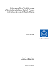
Multicast addresses are in the range 224.0.0.0 through 239.255.255.255. The range
224.0.0.0 to 224.0.0.255 are reserverd and should not be used. Multicast routers
should not forward any multicast datagram with destination addresses in this range.
The set of hosts listening to a certain IP multicast address is called a host group.
Hosts can dynamically join and leave a group. The number of hosts in a group is
unrestricted. [IANA Internet Protocol v4 Multicast Address Assignments]
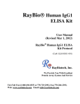
(a) Joining
(b) Receiving
Figure 2.1. Joining and receiving from a multicast group
Joining a multicast group can be as simple as starting an application. Applications that receive multicast transmissions send requests to join multicast groups,
this is demonstrated in (a) in gure 2.1. The host sends a membership report message to its nearest router, as well as to all hosts on the attached interface. Each
membership report contains the multicast address of a single group that the host
has joined.
Once a member has joined a multicast group it will receive all multicast messages
sent to the group, as can be seen in (b) in gure 2.1. In order for multicast to work
over multiple networks, routers and switches need to support the IGMP protocol.
Multicast routers send queries at regular intervals to see if there are any multicast
members left on any of its interfaces. Using queries, multicast routers keep tables
of which of their interfaces have one or more hosts in a multicast group.
2.2 MPEG
The information in section 2.2 refers to [3],[4],[5],[6].
MPEG stands for Moving Pictures Experts Group. The Moving Picture Experts
Group is a working group of ISO/IEC in charge of the development of standards
for coded representation of digital audio and video. MPEG is the name given to
standards used for coding audio and video content in a compressed digital format.
There exists a wide variety of MPEG formats, such as MPEG-1, MPEG-2, MPEG-4
3
and MPEG-7. MPEG uses lossy compression, in that information is lost when the
video and audio data is compressed.
The rst MPEG standard, MPEG-1, was established in 1992. The standard was
designed to t the bandwidth of early CD-ROM's, providing quality comparable
to that of VHS cassettes. The strength of MPEG-1 lies in its powerful ability to
provide relatively high-quality video images while using a high compression ratio.
The MPEG-2 standard was established in 1994 and was designed to provide to
better image quality at higher bit rates. MPEG-2 is capable of delivering true
broadcast quality video and is primarily used by broadcasting companies that provide their content through satellite and cable networks. It is backwards compatible
in that any MPEG-2 decoder can play MPEG-1 content. MPEG-2 has also become
widely spread since it is the coding scheme used by DVD's. The High Denition TV
standard is based on MPEG-2.
MPEG-4 is based on the successful MPEG-1 and MPEG-2 standards and was originally intended for usage with very low bit rates. The standard was initiated in
1995 and nalized towards the end of 1998. What makes MPEG-4 dierent from
MPEG-2 is its ability to integrate content from dierent media sources. It can add
such elements as recorded entities, 2D images and moving 3D computer models.
2.2.1 Multiplexing
The MPEG-2 standard is based on the dierent applications that video and audio
data are used in. The standard also takes into consideration the technology used
to deliver the data. For example, in TV broadcasting several dierent channels are
sent at once to the consumer. The channels are independent of one another. The
various video and audio streams of the dierent channels are multiplexed together
before being broadcasted to the consumer.
Several dierent broadcasting stations send their feeds to a common uplink sta-
Figure 2.2. Multiplexing requires compression on each input
tion. There, the signals are multiplexed before being transmitted to a satellite for
redistribution. The multiplexing stage could be a function of the underlying delivery network. The main drawback of such a system is that the transported data is
highly dependent of the distribution network. In other words, a multiplex based on
4
a certain network topology may not necessarily be compliant with another network
topology.
The MPEG-2 standard is independent of the network's physical implementation.
The standard is well suited for all types of networks, both those that introduce noise
and those that are error-free. The data in the MPEG-2 standard is self-consistent,
in that all required information required to decode the audio and video is packaged
within the bit stream.
2.2.2 Packets
The MPEG-2 standard is based on the usage of packets. Packets are data structures
commonly used within the networking domain. Packets consist of a header and a
payload, both being variable in size. The header contains the necessary information
needed to decode the data payload, the size of the header depends mainly on which
scenario the data payload is used in. This can be seen in gure 2.3.
Packet
Header
Payload
Figure 2.3. Packets consists of a header and a payload
Depending on the underlying transportation medium, variable or xed packet length
is used. This is due to the fact that certain problems arise when packets are sent
along error prone communication systems. Bit errors can damage packets seriously,
which can have grave consequences on the transmitted information. Variable length
packets are commonly used if the medium guarantees error-free transmission. If, on
the other hand, packets are subject to various kinds of faults during transport, it
is useful to have packets of xed sizes that are also relatively short. Small package
size means that little data is lost if a packet is corrupted.
2.2.3 MPEG Streams
In order to cope with various conditions, the MPEG-2 standard denes two basic
tools that support dierent delivery systems. These are known as theprogram stream
and the transport stream. The program stream focuses on short distance delivery
systems, such as hard drives, CD-ROM's, DVD's and other local media storage systems. These environments have a very low error rate, which makes it possible to use
long data structures that are variable in length. The transport stream is used over
error-prone systems such as local area networks. The transport stream packets are
short and xed in size, in order to minimize consequences of packet loss and to be
able to cope with network congestion.
5
My work done at Ericsson consisted of arranging a system that would deliver MPEG2 data over an Ethernet network. This text will focus on the transport stream since
it is the technology used in environments that can cause bit errors.
2.2.4 Transport Streams
The transport stream oers the possibility of multiplexing several audio and video
streams together. It can also take an existing MPEG-2 multiplex and extract a
single program or a collection of programs. Remultiplexing a transport stream is
also possible; remultiplexing is the process of taking existing transport streams, extracting some of their programs, and rearranging them into a new transport stream.
One of the most important objectives of the transport stream is maintaining the
synchronization between the audio and video during the multiplexing process. This
is made possible by adding information in the form of time stamps to the transport
stream. Control and management information are also embedded into the transport
stream.
Unfortunately, there is no error recovery system built into the transport stream.
The control and management information can merely inform the decoder that errors have made their way into the system. Error recovery can be handled by external
systems, such as network protocols, by using information provided by the MPEG-2
transport stream.
Before being converted to a transport stream, the output of an MPEG-2 encoder is
called the elementary stream. An elementary stream is an endless stream of audio
and video information. Storage and distribution system prefer discrete blocks of
information, so the elementary stream is transformed into a packetized elementary
streams, PES. A PES packet begins with a header containing a unique packet start
code, its value is 0x000001, as seen in gure 2.4. It is followed by a code that identies the type of the PES stream.
PES packet
Start code
0x000001
Stream ID
PTS
DTS
Data
Figure 2.4. Example of a simple PES packet. The amount of information contained
within the header is variable.
The PES packet header is variable in length. Certain packet headers contain information that is not constantly transmitted. The most important of the optional
ag are the presentation time stamps PTS, and the decode time stamps, DTS. The
presentation time stamps inform the decoder when the actual information should be
displayed, while the decode time stamp is present if the decoding time of the packet
diers from the actual presentation time. The DTS is always preceded by a PTS.
6
The PES is primarily a logical construct and is not intended to be used for interchange, transport or interoperability. The PES is primarily a conversion point
between program streams and transport streams.
The elementary stream is rst segmented into PES packets and then later on to
transport stream packets. The dierent layers are created with dierent objectives.
During PES packetizing, information such as scrambling and copyright protection
are added to the stream. The information added in the transport stream layer is
used to transport and deliver the data.
The following gure shows the relationship between elementary streams and transport streams.
Variable size
PES header
TS header Data from PES packet
Picture data
TS header Data from PES packet
TS header
Mixed data
hex #FF fills out the
remaining space
Fixed size
Figure 2.5. Relationship between the packetized elementary stream and the transport stream.
The entire contents of the PES packet is divided into smaller pieces and inserted
into the payload regions of the TS packets. Byte stung is used if a PES packet
does not t into a discrete number of TS packets. The hexadecimal value FF is
inserted into the TS packet until its payload is full. This is displayed in the third
TS packet in gure 2.5.
Transport streams can be built up in dierent ways. Single program transport
streams, SPTS, are built up of dierent PES streams that all share a common time
base. Common time base means that the programs are related to one another, such
as in the case of a movie with several dierent audio tracks. The multi program
transport stream, MPTS, is a multiplex of several dierent transport streams.
The MPEG-2 transport stream packet is of constant size of 188 bytes. The packet
consists of a 4 bytes information header, an optional header extension called the
adaptation eld and the data payload that is built up of PES packets. The transport packet header is normally kept quite small, in order to increase the data payload
carried within the packets. The overall size of the packet is always unchanged.
7
188 bytes
Header
Payload
Figure 2.6. The total size of a transport stream packet is always 188 bytes despite
the fact that the header can be variable in length.
The rst byte of the Transport Stream packet header is a synchronization byte of
value 0x47. The remaining 3 bytes of the header are used to identity the payload
of the packet and provide additional decoding information. The most important
information in the header is the packet identier, PID. The PID information is used
to identify the transport packets containing information relevant to a single PES
stream. When a demultiplexer is instructed to listen to a certain PID, it extracts
the packets containing the right PID number and discards the rest.
The adaptation eld is an optional extension of the transport packet header. The
information contained within the adaptation eld is used for clock recovery. The
most important eld is the program clock reference, PCR. The PCR eld is a 42
bit counter which is split up into two parts. The two parts represents two counters,
running at 90 KHz and 27 MHz. As soon as the 27 MHz counter reaches the value
of 300, it is reset to 0 and the 90 KHz part is incremented by one. The reason for
having the PCR eld split into two parts is due to the fact that MPEG-1 was only
using a 90 KHz timebase. The timabase extensions elds are displayed in gure 2.7.
27 MHz
90 KHz
PCR reference base
PCR extension
33 bits
9 bits
Figure 2.7. PCR elds in transport packet adaptation eld.
The PCR eld contains the necessary information required to synchronize the decoder to the encoder clock. The decoder needs an internal clock that is locked to
the encoder clock in order to utilize the decode time stamp and presentation time
stamps contained within the PES packets. To make sure that the decoder clock is
synchronized with the encoder, the PCR signal is transmitted periodically, typically
every 0.1 seconds.
8
Transport stream header
Syncbyte Error Start
Priority
flag flag
0x47
PID
Adapt fld Disc Random Elem.
flag access priority
length
SCR
Adapt
Adapt
Cont
field
contr
Flags
Opt
Stuffing
fields
Extended header
PCR
OPCR
Transport
Splice
countdown private data
Adaptation
extension
Program clock reference
Figure 2.8. The elds contained in the transport stream header.
The decoder uses a voltage-controlled oscillator VCXO, to generate a 27 MHz clock.
When a PCR is received, it is compared to the local counter that is driven by the
VCXO. The dierence in time is used to correct the frequency of the VCXO to ensure that the 27 MHz clock is locked to the PCR. The MPEG-2 standard requires
the PCR packets to arrive in at most 0.1 sec intervals to maintain synchronization.
Control and management information is contained within the transport stream.
Some of this information is used to group audio and video streams together. The
MPEG-2 standard denes a program as a number of elementary streams that share
a common time base. This information is periodically sent within the transport
stream. All required information concerning audio, video and data streams, are
grouped together in Program Specic Information tables, PSI. PSI tables are structures that are linked together. The four basic PSI tables adhere to a certain hierarchy. The four tables dened by the MPEG-2 standard are the following:
PAT - Program Access Table
PMT - Program Map Table
NIT - Network Information Table
CAT - Conditional Access Table
The starting block is the Program Access Table, which is always contained in transport stream packets with the reserved PID value of 0. It provides the initial information on the programs contained in the transport stream. The PAT contains
entries for each program number and their corresponding PID value. The packets
corresponding to the PID values are in turn tables that contain program specic
information. These tables are called program map tables.
9
PAT
PID 0
Program 0
Program 1
Program 2
Stream 1
Stream 2
Stream 3
Stream 4
Stream 5
V
A
A
A
D
18
35
50
NIT
PID 18
Stream 1
Stream 2
Stream 3
Stream 4
52
53
54
56
60
V
A
A
D
17
36
38
41
PMT 2
PID 50
PMT 1
PID 35
Figure 2.9. The PSI tables are used by the MPEG-2 demultiplexer.
The Program Map Table, PMT, contains the PID's of the packets that belong to
a specic program. These PID's identify the transport packets carrying the audio
and video packets of a specic program. These PES streams are extracted from the
transport stream and routed on the decoder.
The PID linked to the rst row in the PAT points to the Network Information
Table. The main role of the NIT is to deliver information about the delivery network. The information contained in the NIT is not dened by the MPEG-2 standard.
The Conditional Access table contains information about the encryption methods
used for each individual program. The PID used to identify this table always has
the value 1. The CAT contains the PID's of certain packages that carry information
about the scrambling systems.
10
Chapter 3
The Setup
3.1 Installation
The idea at Ericsson was that I build a video server system based on standard PC
equipment. The original mockup consisted of a PC running on Linux with a PCI card
capable of receiving digital satellite transmission. The computer I was supplied with
was a low-end Pentium II running at 300 MHz. The processing power was deemed
sucient since the machine would not be transcoding any part of the MPEG-2 transport stream. My objective was to congure the system to receive broadcast digital
TV and stream the corresponding MPEG-2 transport stream through a network.
3.1.1 The operating system
My rst task was to install a Linux operating system on my PC. The Linux operating system is available in several dierent versions called distributions. Ericsson
uses Debian Linux distribution. This is why I opted to install this distribution on
my PC. The Debian installation process turned out to be quite a laborious task.
Very little information is provided regarding the install process of the base system.
The installation program requires a great deal of information about the hardware
and network conguration.
The rst installation attempts failed due to the fact that the graphics card in my
PC conicted with the Debian distribution. Unable to overcome the problem, I
attempted to try another Linux distribution. The Red Hat distribution installation
process worked awlessly and installed itself on my computer. The victory was shortlived since issues regarding software installation quickly arose. Since Linux bases
itself on open-source software, most programs are downloadable in source code format only. Because of this, dependency issues can take place when attempting to
compile programs. Some programs require additional source code not available with
the base installation. These dependency problems often cascade; source code les
often depend on other source code les. The Debian distribution has software that
handles these issues. It is called the APT manager.
11
Because of this, I attempted to reinstall the Debian package on my PC. Through
hours of Google searching, I had managed to pinpoint the reason why the rst installations had failed. The Matrox graphics card installed in my computer did not
support frame buering. This caused Debian to display No screens found on the
screen during start-up. By editing a conguration le the problem was solved. The
required conguration is displayed in gure 3.1
Required Software
- Debian Linux distribution installation CD’s
Configuration
Various problems can arise during the Debian installation process . Certain graphics
cards are not 100% compatible with the distribution , notibly certain Matrox cards . In
order to work around the incompatibilty issue , it is imperative that one does not select
frame buffering option when asked during the installation process . Should frame
buffer misstakenly be selected it can be unselected after the installation by running
dpkg-reconfigure xserver -xfree86 and not selecting frame buffering .
Figure 3.1. Debian Linux Setup
3.1.2 Streaming software
Through the Debian APT manager, I downloaded a program package known as the
Video LAN Client, VLC. The VLC package is software written by a group of computer students at the École Polytechnique in Paris. The software can be used for
streaming video over a network and for viewing various video formats.
My rst attempts to stream video over our local network proved to be successful. By using VLC as a server, I managed to send a MPEG-2 le from my computer
to a nearby computer running VLC as a client. Both computers were connected
through a switch that supported multicast. The MPEG-2 signal streamed perfectly
for several minutes. The required conguration is displayed in gure 3.2.
12
Switch
Server PC
Client PC
Required hardware
- 2 PC’s equipped with network interface cards
- 1 switch with multicast support
Required Software
- VideoLAN Client
downloadable from www.videolan.org
Configuration
Both PC’s must have the VideoLAN Client software installed on them . The
software can be downloaded from www .videolan .org or through the Debian
package manager . The installation process is straightforward . Additional
information regarding installation and user manual for VideoLAN Client is available
from www.videolan.org
The file that is streamed must be supported by VideoLAN Client . VideoLAN
supports various video file formats , but it is recommended to use an MPEG -2 file.
Figure 3.2. PC to PC streaming setup
The next step was to stream an MPEG-2 signal to a set top box connected to a
TV. Ericsson has a standardized set top box that has a built-in Ethernet network
adapter. It is used in conjunction with the Tandberg video streamer. In order to send
a correct transport stream, I was provided with a CD-ROM containing an MPEG2 compliant transport stream le. I chose to use the Video LAN Server software,
VLS, instead of the VLC. VLS is a scaled down version of the VLC, which requires
less resources on the PC. Saving resources was essential due to the nature of the task.
The set top box communicates with the network through an html interface. The
html interface consists of a web page containing a list of available programs in addition to several special tags, essential to the set top box. The special tags contain
information such as PID numbers for the audio and video streams. By conguring
an Apache web server on my PC, I provided the set top box with the necessary
communication to view the test transport stream. By clicking on one of the links on
the web page, the set-top box tuned itself to the parameters specied within the tags.
The VLS bases its streaming on a conguration le called vls.cfg. This le can
be found at the end of this report. The conguration le controls such parameters
13
as the multicast address, the multicast port, and the type of le being streamed.
Once congured, VLS managed to stream the Ericsson promo transport stream contained on the CD-ROM. The required conguration is displayed in gure 3.3.
Server PC
Switch
Set top box and TV set
Required hardware
- 1 PC equipped with a network interface card
- 1 switch with multicast support
- 1 Ericsson set top box and a TV set
Required Software
- VideoLAN Server
downloadable from www.videolan.org
- Apache Web Server
can be selected during Linux installation or installed through the apt
- MPEG-2 compliant Transport Stream
Ericsson promo Transport Stream is available from Örjan Sahlin
Configuration
The VideoLAN Server is used for streaming to set top boxes . It proved to work
better than the VideoLAN Client . VideoLAN Server is available through the apt or
from www.videolan .org. VideoLAN Server is available in source code only if
downloaded from the videolan homepage . Complete VideoLAN Server installation
instructions and user manual are available on http ://www.videolan .org/doc/
The Apache web server does not require any special configuration . Apache
documentation can be found on www .apache.org. It is recommended to include
the Apache web server during the Debian Linux installation process .
The html interface is used as a menu and allows users to select a desired channel
on the TV screen . It is essentially a html document that contains special HTML
tags. Tag information and set top box setup instructions are included in the
MediaBase Video Server & Ericsson Set -Top Box document written by Ulf
Collovin. It is available from Ericsson .
Figure 3.3. PC to set top box streaming setup
3.1.3 Hardware
Once the software proved to work correctly, I proceeded to work on the reception
cards. I was tted with two reception cards from Hauppauge, one for satellite Digital
Video Broadcasting, DVB, called NOVA-s and another for terrestrial DVB called
14
NOVA-t. Both models were PCI cards. None of the cards contained any MPEG-2
decoding hardware. The boxes containing the cards stated that they were Plug&Play
models in Windows, but needed advanced conguration in Linux.
DVB drivers needed to be downloaded and installed on the system in order for
the cards to work in Linux. A web site called LinuxTV provided numerous links
to various Linux DVB drivers. The drivers proved to be stubborn and would not
compile or install themselves on the system. I had previously received help from a
person who had altered certain Linux system variables. By mistake, he had changed
these values to point to old header les used by the Linux kernel.
The faulty system variables were discovered by chance. The drivers worked perfectly once the system variables were recongured to point to the correct header
les. Before the error was corrected it was thought that the underlying hardware,
such as the satellite equipment, was at fault. Luckily, this was not the case.
In order to prepare the system for the Linux DVB drivers, certain steps have to
be taken, these are displayed in gure 3.4
Required Software
- Debian Linux Kernel Source files version 2.4.18 or greater
downloadable from www.kernel.org or through the apt
- Linux DVB drivers
downloadable from http://www.metzlerbros.org/dvb/ or from
http://linuxtv.org or through the apt
Configuration
In order for the Linux drivers to work , the Debian Linux environment must be configured :
• Source files for kernel 2.4.18 must be downloaded to the PC
• The kernel has to be compiled and configured with loadable module support , and i2c
and videodev activated .
You can download new kernels from http ://www.kernel.org. Once the files are
downloaded they need to be unpacked and compiled . A good guide for this can be
found on http ://www.linux.org/docs/ldp/howto/Kernel-HOWTO/.
Before compilation , the kernel must be configured to enable loadable module support ,
i2c and videodev . This is done by running make config , make xconfig or make
menuconfig.
The Linux DVB drivers can be downloaded from either of the two links . Installation
instructions can be found in the README and INSTALLATION files contained in the
Linux DVB driver tar .gz file.
Figure 3.4. Debian kernel setup
15
3.1.4 Satellite setup
The satellite dish on the Ericsson rooftop in Telefonplan, Stockholm, was a professional system. Originally, it was thought that the NOVA-s PCI card was incompatible with the Low Noise Block downcoverters, LNB, microwave heads. LNB heads
are the components inside the satellite dish that receive the satellite signals.
The LNBs in the satellite dish were locked to specic frequencies. Normally, LNB
heads can be tuned to dierent frequencies using a satellite receiver. Since this was
not the case, it was believed that the tuning software used with the satellite dish was
trying to unsuccessfully tune the LNB heads. In order to rule out that possibility,
I debugged and traced the tuning program's source code. In the end I could nd
no reason for program or hardware conict. It was only later that it was discovered
that the Linux DVB drivers were the cause of the malfunction.
Several weeks had gone by during the debugging process, but once the drivers were
working I could promptly tune the NOVA-s card to any given frequency. I was able
to tune the card to dierent frequencies and zap between channels.
3.1.5 Conguration les
Once the drivers were up and running, VLS had to be congured. VLS uses a le
called .dvbrc to tune itself to dierent channels. This is true for both terrestrial and
satellite DVB. There is no practical scan program available to search for channels
over any given frequency band.
Ironically, there exists a small application supplied with the Linux drivers called
scan. The scan program is part of the libdvb package. No documentation is provided for scan. It was a challenge to gure out how to use it, but by going through
the program's source code I could determine how to get it started. Scan is a command line program that requires a .dvbrc as an argument. Figure 3.5 shows an
example of how to use scan.
scan
The example assumes that a valid .dvbrc file lies in the /root/ directory
- Enter the directory entitled libdvb -xxx
- Start scan by running the following command :
/libdvb-1.5.2/./scan /root/.dvbrc > temp_file
temp_file will now contain the information contained in the .dvbrc file along
with all the programs available at the given frequencies .
Figure 3.5. Scan usage example
16
A .dvbrc le contains amongst other things frequencies, symbol rates, and FEC
codes. In other words, the initial .dvbrc le must contain most of the information
one would hope to obtain using a scan program! A compliant and working .dvbrc
le can be found in Appendix A at the end of this report.
VLS expects the .dvbrc le to lie in the /root/ directory. The only lines in the .dvbrc
le that need to be modied for additional channel reception are the TRANSPONDER rows. The TRANSPONDER rows are required to have unique ID numbers;
the rst TRANSPONDER row should have ID 001, the next ID 002 and so on. It
is of extreme importance that the TRANSPONDER rows refer to the same SAT
ID number throughout the .dvbrc le. The values in the TRANSPONDER rows
that should be modied for each transponder are FREQ, POL, SRATE and FEC.
All these values can be found on http://www.lyngsat.com. By selecting the desired
satellite one can identify the four values in that satellite's frequency table. FREQ is
labelled Freq, POL is labelled Tp, SRATE is labelled SR and FEC is labelled FEC
in the lyngsat tables.
Once I provided a correct .dvbrc le to the scan application, it managed to nd
the channels available at the frequencies I had added to the le. The output of the
scan program was a le almost identical to the input .dvbrc le, the dierence being
that it also contained the channels available at each frequency.
Now that I had a proper satellite .dvbrc le, I managed to stream a satellite channel to the set top box. The box could indeed display the channel contents for a
short while, but the stream was not perfect since the image disappeared after approximately four minutes. The result was the same with other channels, so divine
interference was ruled out as a possibility.
3.1.6 Terrestrial setup
The second part of conguring the computer consisted of setting up a receiver for
terrestrial digital video broadcast. Terrestrial signals are emitted from TV-towers.
They dier from satellite signals in that they carry additional information needed
for error correction. Terrestrial DVB signals are prone to interference such as ghost
images and electrical noise caused by high-rise buildings, heavy power usage and
interfering radio signals.
The Linux DVB drivers work with both satellite and terrestrial broadcasts. Much
like its celestial counterpart, the terrestrial receiver refused to work initially. The
drivers were not the cause of the malfunction so the problem had to lie elsewhere.
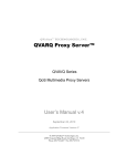
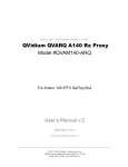
In order to see how sensitive the reception of the Nova card was, a test antenna
made from an old coat hanger was used.
17
Figure 3.6. The coat hanger antenna.
As a reference, I used a Nokia Mediamaster terrestrial digital video receiver as reference to position the antenna to get an optimal signal. The signal proved to be
quite weak, due to the fact that the building we were in was covered with aluminum
siding. The aluminum sheets eectively shielded us from TV-signals. The Nokia
set top box proved to be quite tolerant of weak signals and managed to produce
a ickering image on the TV screen. The image was often distorted by pixelation
due to discontinuities in the MPEG-2 transport stream, caused by weak TV-signals.
The result was that the Nova card denetely needed a strong signal.
Once the antenna was positioned I knew that I should be able to get at least some
read-out from the terrestrial DVB card. I tested dierent channels and dierent
.dvbrc settings but none worked. By chance, I managed to spot a small commentary line in one of the several header les used by the Linux DVB driver les. It
stated that in order to make the terrestrial card run under Linux, a small .dll le
should be copied from the Hauppauge Windows driver CD and placed in the Linux
system. This little suggestion did the trick, and the terrestrial card awoke. By
conguring the terrestrial .dvbrc le using the scan program, I got VLS to work.
A faint and completely pixelated image was displayed by the set top box for a few
seconds. The required conguration can be found in gure 3.7.
Required Software
- Hauppauge Nova Installation CD
Configuration
In order to extract the necessary file , one must first install the NOVA -t card and its
drivers on a PC running Windows . When the card is installed and configured in
Windows, the file ttlcdacc.dll can be copied from C:\Program Files \Hauppauge \
WinTV NOVA\ . This file should be renamed tda1004x.mc, and placed in the
/etc/dvb/ directory.
Figure 3.7. NOVA-t setup
18
3.1.7 Live capture
The idea of using a software MPEG-2 capture card to stream video from a video
camera was abandoned quite early, since the equipment I had at my disposal was
not capable of real-time MPEG-2 encoding. According to various MPEG-2 encoding message boards, the minimum requirements for real-time software encoding of
MPEG-2 is a Pentium 4 running at a speed of at least 2.4 GHz with at least 256
MB RAM. I had a Pentium II running at 0.3 GHz with 128 MB RAM.
19
Chapter 4
Analysis
4.1 Preliminaries
During test periods, the set top box could receive and display MPEG-2 transport
streams for a period varying between 4 and 7 minutes. The up-time depended
on the set top box used. According to various experts at Ericsson, such as Mikhail
Soloviev, certain boxes were crankier than others. Quite simply, some boxes proved
to be more tolerant to awed MPEG-2 transport streams.
4.2 Signal study
In order to determine the cause of the erroneous signal I set out to compare the
MPEG-2 transport stream generated on my PC with the correct MPEG-2 transport
stream generated on the Tandberg IP streamer. I placed two network cards in a
second PC and installed an Ethernet network snier program called Ethereal.
Ethereal is a program used for troubleshooting, analysis, software and protocol development. Ethereal is a network protocol analyzer, or packet snier, that lets
you capture and interactively browse the contents of network frames. It runs on all
popular computing platforms, including Unix, Linux, and Windows.
The plan was to make two simultaneous dumps of the packets sent out by both
systems. I tuned both my PC video server and the Tandberg to the same satellite
channel. I chose a test card channel with a static test pattern for sake of simplicity.
To my mild disappointment, the snier was not able to make simultaneous dumps
from the two systems. This was no cause for concern since the feed from the channel
was static. All I had to do was take two successive dumps and save them on le for
later comparison. The conguration is displayed in gure 4.1.
20
Tandberg IP streamer
PC with 2 network interface cards
PC video server
Required hardware
- Tandberg IP video streamer
- 1 configured PC video server
- 1 PC equipped with two network interface cards
Required Software
- Ethereal
downloadable from www.ethereal.com or trough the apt
Configuration
Ethereal can easily be downloaded and installed under Linux from
www.ethereal .com or through the apt . Ethereal documentation and user manual
can be found on www.ethereal.com/docs.
Figure 4.1. Snier setup
My intent was to pinpoint crucial dierences between the packet streams. Every
packet seemed dierent, it was found that the Tandberg systems inserts additional
information into the transport stream before it sends it to the Ethernet network. A
byte per byte comparison of the signals would therefore be dicult.
Instead, I wrote a small JAVA application that opened a multicast socket to the
video server and proceeded to record a raw transport stream without any network
protocol overhead. The source code for the JAVA application can be found in appendix C. The recording would enable me to search through the transport stream
data to nd any errors. Unfortunately, the specics of the MPEG-2 standard are
very complicated and a manual parse of the data would require much knowledge of
the form of the transport stream. There exists software capable of analyzing and
determining the compliance of an MPEG-2 transport stream, such as the Manzanita
MP2TSA. Unfortunately, no such software was at my disposal, but some ndings
will be reported in section 4.4 below.
21
There were concerns that the packets might be larger than maximum allowable
Ethernet frame size of 1500 bytes. Measurements made with Ethereal showed that
the packets transmitted trough the network had a total size of 1358 bytes.
When packets are larger than the maximum frame size, they are divided into series
of smaller packets that t into Ethernet frames. These smaller frames are sent out
on the network as bursts of packets. This sudden amount of trac on the network
can cause congestion and packet jitter. The measurements proved however that this
was not an issue.
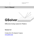
4.3 Demonstration
Towards the end of my period at Ericsson, a demonstration system was mounted.
The demonstration consisted of streaming High Denition TV from my video server
through a network controlled by a COPS protocol. The COPS protocol regulates
quality of service issues such as bandwidth. Since the set top boxes were not able to
process the high bit rate HDTV transport stream we used a powerful PC as client.
The client PC was equipped with a Pentium IV processor clocked at 2,0 GHz. The
PC was hooked up to a high-denition projector. This is displayed in gure 4.2.
Client
Video server
Figure 4.2. The demonstration system.
We noticed a remarkable dierence in required processing power between the video
server and the client. The processing power of the Pentium II running at 300 MHz
was sucient to stream video, but the Pentium IV 2,0 GHz client PC was barely
able process the tremendous amount of data. The client regularly dropped frames to
stay in sync with the signal. Decoding video requires much more processing power
than streaming the same signal onto the network.
I expected the video to freeze or go blank after a few minutes, but the video feed
continued working for several hours. When left streaming, the system stayed up for
22
a continuous period of 12 hours. This proves that the MPEG-2 transport stream is
not entirely corrupt.
4.4 Theories
Due to lack of time I was not able to determine the nature of the MPEG-2 errors.
Instead, I will list a number of theories to why the MPEG-2 stream causes the set
top box to go down after only a few minutes.
The Program Map Table denes the packets carrying PCR information for a given
program. If the PMT should fail to point out the correct PID packets, then the
decoder will lose sync over time, resulting in screen freezing or image blanking.
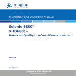
Another possible cause of error is PCR jitter. The use of LAN networks to transmit resynchronization timestamps introduces certain problems. Transmission delays
are not always constant within a network. If the PCR packets are delivered with
varying delays the decoder clock could be aected. The decoder system uses a
phased-locked-loop, PPL, an analog system used to average out disruptions in the
PCR ow. Should however the delays vary too much then the PPL might not be
able to compensate for the variations, as shown in gure 4.3.
Encoder time
1
1+A
1+B
1+C
1+D
am
{
4
p3
p2
p1
tamp
imes
est
T im
am
est
T im
am
est
T im
T
PCR
PCR
PCR
PCR
delay T
1+T
1+A+T
1+B+T
1+C+T
1+D+T1
Decoder time
Figure 4.3. PCR transmission.
The most straightforward method for measuring the network jitter as it aects the
MPEG-2 Transport Stream is to use two Transport Stream analyzers, one on each
end of the network, as shown in gure 4.4.
23
Video server
Video client
MPEG-2 transport stream
MPEG-2 transport stream
Transport stream analyzer
Transport stream analyzer
Network interface
Network
Network interface
Figure 4.4. Setup for PCR jitter measurement.
Most Transport Stream analyzers available today will measure the PCR errors directly in nanoseconds, usually as a histogram. By comparing the PCR jitter at the
output of the network with the PCR jitter measured at the input of the network,
this error can be used as a direct measure of the maximum cell delay variation
experienced by the transport stream as it propagates through the network. Jitter
performance over IP based networks should improve if the streaming protocol uses
shorter packets, at the expense of additional packet overhead.
The set top boxes contain memory chips that buer the incoming video stream.
If the memory buer lls up for some reason, it might not be able to continue decoding the MPEG-2 signal properly. The PC system used during demonstration
stayed up for a period of 12 hours, perhaps due to the fact that it was more resilient
to incompliant MPEG-2 bit streams. The 256 MB of RAM were also probably more
than sucient when used as buer memory.
It is unclear at this time how the Linux drivers handle the PCR packets, it might
relocate them erroneously in the transport stream. The source code for the drivers
should be looked at in more detail in order to rule this possibility out.
As I was writing this report, I was supplied with more information regarding errors
contained within the transport stream. A 100 MB le was analyzed by a company
called ESDG which is based in Linköping. The company specializes in MPEG and
have a great deal of knowledge of the MPEG standard. They also have software at
their disposal which is capable of analyzing transport streams. The analysis showed
that there were discontinuities in the transport stream at three second intervals.
The error log can be found in the appendix section of this report.
The discontinuity is due to the fact that the continuity counter elds are nonsequential. This may be caused by missing packets or by the software if it changes the
values of these elds. According to the technicians at ESDG, this may very well be
24
the reason why the set top box goes black after approximately four minutes.
MPEG-2 carried at the 188-byte Transport Stream packet level is in essence unprotected and transportation needs to take place across almost error-free links. If
the IP transport network cannot guarantee very low levels of error rates, then for IP
multicast some form of forward error correction scheme should be used. Bit errors
in an IP layer will be reected in whole frames being dropped at the MAC layer,
due to checksum failures. Hence, the protection scheme should not work on the bit
level as is the case for satellite links for example.
A more ecient method is to add a Forward Error Correction, FEC, at the IP
frame level. The simplest technique is to XOR together the IP frames and then
regularly approximately every 20th frame send the XOR sum on a separate UDP
port. The receiver will be able to detect if a packet has been lost by inspecting the
sequence number in the RTP header. The lost packet can be recreated by XORing
all the received packets (excluding the one lost) plus the FEC packet. [RFC2733]
describes a method for this.
25
Chapter 5
Conclusion
It was determined that a low-cost alternative to the Tandberg streamer might be
possible. Although a perfect replacement machine was not achieved, I was able to
congure a system capable of demonstrating the potential of a PC based videoserver. Much more analysis work must be done in order to obtain a system capable
of delivering a perfectly compliant MPEG-2 stream.
Various problems such as network jitter and bit errors are probable causes to the
incompliance of the MPEG-2 transport stream. Network jitter can be studied with
the use of network analyzers by doing two point measurements. If jitter is present,
its negative eects can be minimized by using shorter packets, with the expense of
additional packet overhead.
The recurring transport stream discontinuity errors are a cause for concern. They
can be caused by the satellite card, the Linux DVB drivers or even the VLS streaming software. Analysis programs will most likely be of great use when trying to
pinpoint the exact cause of the transport stream anomaly.
The fact that a demonstration system streaming HDTV managed to stay up for
several hours proves that the generated MPEG-2 transport stream is not entirely
corrupt. The PC decoding the HDTV signal had more processing power and more
buer memory than the Ericsson set top boxes I used. This might the reason it
could withstand the discontinuities in the transport stream and decode the stream
for more than 14 hours.
26
References
[1] Francois Fluckiger. Understanding networked multimedia. Prentice Hall, 1995.
[2] Atul Puri and Tsuhan Chen. Multimedia systems, standards, and networks.
Marcel Dekker, 2000.
[3] Martin J. Riley and Iain E.G. Richardson. Digital video communications. Artech
House Publishers, 1997.
[4] Tektronix. A guide to MPEG fundamentals and protocol analysis.
[5] John Watkinson. The art of digital video. Focal Press, 3 edition, 2000.
[6] John Watkinson. MPEG-2. Focal Press, 2000.
27
28
Appendix A
.dvbrc le
The following pages contain an example conguration for both terrestrial and satellite digital video broadcasting.
29
Appendix B
Transport stream error log
The following pages contain the error log that was created while analyzing a transport stream generated by the video server.
30
Appendix C
SocketReader
Source code for SocketReader.java
31


![Corel Office Document [PFP#241512617]](http://vs1.manualzilla.com/store/data/005699212_1-655f6a875c479857ca50d39f97eeaf8f-150x150.png)