1
OPS675
Cutting Plotter Controller
User's Manual
MANUAL NO.OPS675-UM-152
Software Usage Agreement
Cautions
Registered Trademarks
Graphtec Corporation ("Graphtec") hereby grants the purchaser and authorized User (the "User") the
right to use the software (the "Software") in accordance with the terms and conditions specified. By
its purchase and use of the Software, the User hereby accepts and agrees to abide by the terms and
conditions set forth herein.
1. Copyright
All copyrights relating to the Software and accompanying printed materials such as manuals shall be
retained by the individuals or organizations indicated in the Software or printed material.
2. License
The User may use the Software on one computer at a time.
3. Copying and modification
(1) The User may copy the Software for backup purposes. In that case, the User should label the
copy with the same copyright notices as apply to the Software.
(2) The User may not modify, combine, amend, or otherwise adapt the Software by any means,
including disassembly and decompiling.
4. Third-party use
The User may not transfer, assign, or otherwise dispose of the rights relating to the Software or its use
to third parties.
5. Warranty
(1) Should the Software not operate correctly due to physical defects in the Software storage medium,
contact your retailer. The product will be exchanged free of charge in the case of a physical
manufacturing defect.
(2) Graphtec only guarantees the storage medium under the above situation.
(3) Graphtec provides the Software on an "as is" basis. Neither Graphtec nor the supplier guarantees
the performance or results that may be achieved using the Software and accompanying
documentation. Neither Graphtec nor the supplier gives any explicit or implicit guarantees
regarding the infringement of a third party's rights arising from the use of the Software or
accompanying manuals, their commercial performance, or their suitability for specific purposes.
Neither Graphtec nor the supplier assumes any responsibility for incidental, secondary, or
special damages resulting from the use of the Software or accompanying manuals under any
circumstances, including cases in which the possibility of that particular damage arising is
indicated to the User by the retailer. Moreover, neither Graphtec nor the supplier assumes any
responsibility for claims from third parties.
•The company names and product names described in this manual are registered trademarks of their
respective owners.
•The "OPS675" software and this manual are copyrights of Graphtec Corporation.
Notes on this Manual
•The contents of this manual may not be copied in part or in whole without permission.
•The details and product specifications in this manual are subject to change without notice.
•The greatest effort has been taken to ensure the clarity and accuracy of the information in this
manual. Please contact Graphtec or your retailer with any questions you may have.
•Please note that Graphtec assumes no responsibility for any liabilities arising out of the use of this
manual and product.
Disclaimer
Some of the software images used in this manual are those that were used when the software was
under development, and they may be slightly different from those actually displayed. There are no
differences between the functions and setting layouts shown here and those of the actual version. We
ask for your understanding.
About This Manual
This manual explains how to set up and operate the cutting plotter ( the "plotter") by using the Cutting
Plotter controller (the "controller") from a computer.
For information on setting up the plotter and installing the software, see "Setup Manual".
For information on operations from the control panel of the plotter, see "User's Manual".
*Chapter 2 and Chapter 4 through Chapter 9 in this manual describe the operations and settings that can
be done from the menu screen that is shown by pressing the [CONDITION] key or the [MENU] key on the
operation panel of the plotter. These chapter titles are followed by the corresponding plotter key or menu
item names so that you can easily refer to "User's Manual".
Symbols Used in This Manual
Screen Images Used in This Manual
The following symbols are used in this manual.
Screens that appear when FC8600 is connected to Windows 7 are used.
CAUTION : Used to indicate cautions and restrictions to be observed for proper operation. Be sure
to read the description that follows this label.
Reference : Used to indicate information useful for operation and additional explanations.
: Used to indicate pages and User's Manuals that contain relevant information.
Æ
[ ]
: Used to indicate the keys on the computer keyboard and the buttons on the controller.
Table of Contents
12. Index....................................................................................................34
Software Usage Agreement........................................................................................ 2
Cautions...................................................................................................................... 2
About This Manual...................................................................................................... 3
Symbols Used in This Manual..................................................................................... 4
Screen Images Used in This Manual.......................................................................... 4
Table of Contents........................................................................................................ 5
1. Introduction to the Controller................................................................6
Features...................................................................................................................... 6
Preparation to Use...................................................................................................... 6
Starting the Controller................................................................................................. 7
Nomenclature (Main Screen)...................................................................................... 9
2. Setting Tool Conditions [CONDITION]................................................11
Basic Settings........................................................................................................... 11
Advanced Control of Tool Behavior.......................................................................... 13
Cut Test..................................................................................................................... 14
3. Managing Media List............................................................................16
4. Tools Setting [TOOL]............................................................................18
5. Setting Area Parameters [AREA]........................................................21
6. Interface Setting [I/F]...........................................................................23
7. ARMS Setting [ARMS]..........................................................................24
Registration Marks Setting........................................................................................ 24
Settings in the [Registration Mark Settings] Screen................................................. 25
Settings in the [ARMS Setting] Screen..................................................................... 26
8. Media Setting [MEDIA].........................................................................28
9. Advance [ADV.].....................................................................................30
10. Option Settings...................................................................................31
11. Troubleshooting..................................................................................33
List of Error Messages.............................................................................................. 33
Uninstalling the Controller......................................................................................... 33
1. Introduction to the Controller
Features
Preparation to Use
Operation Environment
●Easy Setting from Your Computer
The controller enables you to set up and operate the plotter from your computer. Relevant settings are
displayed on a single screen and you can easily find the setting that you want to see. You can use the
driver to start the controller from the print menu in the application software and efficiently proceed a
series of works ranging from image design to cutting.
The following system environment (higher environment than one your OS recommends) is required to
use the controller.
OS
CPU
Memory
Monitor
Network interface
USB Interface
Serial Interface
Device
●Saving Tool Conditions
Up to 100 tool conditions that are set in the controller can be saved to the media list. Contents in the
media list can be saved as a file and loaded to your computer.
●Loading Plotter Setting/Uploading Settings to the Plotter
Tool conditions that are set in the operation panel of the plotter (Condition No. 1 through 8) can be
loaded to the controller. You can edit the loaded settings in the controller and upload them to the
plotter.
Windows XP/Vista/7/8 (32bit/64bit)
Intel Pentium 4/AMD Athlon 64 or greater
1GB or greater
1024 x 768 True Color is supported
10 Base-T/100Base-TX
USB 2.0 (Full Speed)
RS-232C compliant
Mouse
DVD-ROM drive
CAUTION
●Retrieving Information from the Plotter
You can retrieve error and condition information from the plotter and save it as a file.
To use the controller, the plotter must be connected to the computer using a USB, LAN (network), or RS-232C
interface.
●Importing/Exporting Advanced Settings
You can save advanced settings to any location on your computer as well as load setting files that
have been saved.
Checking the Settings in the Plotter
To use the controller, [USER PRIORITY] in the plotter must be set to [KEYPAD/BY PC]. For more
information on the setting, see Chapter 4 "Convenient Functions" in User's Manual.
CAUTION
· Do not control more than one plotters by the controller. Depending on the operations, the settings in the
plotters may not be properly controlled.
Installing the Controller
· When using the Cutting Master 3 / Graphtec Studio, do not use the controller. You will not be able to properly
control the plotter settings.
The controller is installed with the driver when you set up the plotter in Windows XP/Vista/7/8. For more
information on how to install the controller, see "Setup Manual".
For information on how to uninstall the controller, see "Uninstalling the Controller" (Æpage 33).
Reference
· Cutting Master 3, the software that comes with the plotter, can output data that is created in Adobe® Illustrator
® or CorelDRAW® (Windows only) directly to the plotter. Use Cutting Master 3 to output data that is created in
Adobe® Illustrator® or CorelDRAW®. For more information on Cutting Master 3, see the User's Manual
provided with Cutting Master 3.
· The data created by the Graphtec Studio software supplied with the plotter can be directly output to the
Plotter. For more information about the Graphtec Studio, see the User's Manual included with the Graphtec
Studio.
1 . I n t ro d u c t i o n t o t h e C o n t ro l l e r
Starting the Controller
Starting from the Print Menu
The controller can be started either from the print menu in the application software or the Start menu
on the desktop.
1. Open an image that you want to plot in the appropriate application software.
2. Select the print command from the menu.
CAUTION
Reference
· To use the controller, [USER PRIORITY] in the plotter must be set to [KEYPAD/BY PC]. For more information on
the setting, see Chapter 4 "Convenient Functions" in User's Manual.
Operations are different depending on the types of application software. For more information, see the manual
provided with the application software.
· Before starting the controller, make sure that your computer and the plotter are connected properly and that
media is set in the plotter.
3. Select the plotter from the printer list.
· Cuttings other than test and cross cuttings cannot be done when you start the controller from the Start menu.
· To start the controller from the print menu, [Start up the controller] must be checked. This option is in the
[Options] tab of [Printing Preferences] in the driver software.
Reference
For more information on operating the controller screen, see "Nomenclature (Main Screen)" (Æpage 9).
*The screen image above is an example from a Microsoft WordPad print screen.
1 . I n t ro d u c t i o n t o t h e C o n t ro l l e r
Starting from the Start Menu
The controller starts.
1. From the Start menu, select [(All) Programs], [Graphtec Cutting Plotter Controller for FC8000], and
then [Cutting Plotter Controller for FC8000].
The controller starts.
1 . I n t ro d u c t i o n t o t h e C o n t ro l l e r
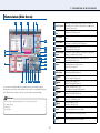
Nomenclature (Main Screen)
3
6
2
7
1
25
24
23
22
21
20
19
16
4
5
8
9
10 12 14 15 13 11 17 18
You can select a tool condition suitable for the plotted media or run a test cutting or cutting by
specifying the position of the tool and the orientation of the media. You can also display the help and
version information of the controller or open the screen for advanced and optional settings.
Reference
Some of the buttons are assigned keyboard shortcuts. The shortcut keys are as follows:
−[Use Keyboard]→[F6]
−[Origin]→[F5]
−[Cut Test]→[F8]
1
User1/2: User Name
Indicates the mode to which the plotter is set: User1 or User2. The
name that is set in [User Name] on the [Option] screen (Æpage 32) is
displayed as the user name.
2
Settings Display
Area
Displays the settings (tool, force, speed, accel, and offset) for the tool
condition that is currently selected.
3
Tool Condition
Lists tool conditions from Condition No. 1 through 8. Click a condition to
select it.
4
Edit Conditions
Opens the [Edit Conditions] screen.
Æ2. Setting Tool Conditions [CONDITION] (page 11)
5
Edit Media List
Opens the [Edit Media List] screen.
Æ3. Managing Media List (page 16)
6
Upload Setting to
plotter
Overwrites the condition settings (tool conditions) in the plotter by the
settings (tool conditions) in the controller.
7
Cut Test
Runs a test cutting under the tool condition that you set.
ÆTest Cutting Patterns (page 15)
8
Rotate
Sets the plotting direction against the media or the direction to set the
media printed by the printer in the plotter.
ÆSelecting Rotation (page 10)
9
Registration
Marks Setting
Used for a cutting where the registration mark is scanned.
Æ7. ARMS Setting [ARMS] (page 24)
10
(TOOL)
Opens the [Tools Setting] screen.
Æ4. Tools Setting [TOOL] (page 18)
11
(ARMS)
Opens the [ARMS Setting] screen.
Æ7. ARMS Setting [ARMS] (page 24)
12
(AREA)
Opens the [Area Parameters] screen.
Æ5. Setting Area Parameters [AREA] (page 21)
13
(MEDIA)
Opens the [Media Setting] screen.
Æ8. Media Setting [MEDIA] (page 28)
14
(I/F)
Opens the [Interface] screen.
Æ6. Interface Setting [I/F] (page 23)
15
(ADV.)
Opens the [Advance] screen.
Æ9. Advance [ADV.] (page 30)
16
Cancel*1
Cancels the setting and closes the controller.
17
Cut*1
Cuts the media based on the settings you made.
18
Close*2
Cancels the setting and closes the controller.
1 . I n t ro d u c t i o n t o t h e C o n t ro l l e r
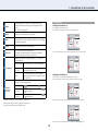
Selecting Rotation
19
Option
Open the [Option] screen. It is able to check the error data and
conditions of the Plotter main unit, and also to import/export the set
content.
Æ10. Option Settings (page 31)
20
About...
Displays the version information of your controller.
21
Help...
Displays the help of the controller.
Pressing the [F1] key on the computer keyboard at each screen displays
the help on the setting item.
22
Origin
Sets the current tool position as an origin point.
23
Cross Cut
Cuts off the media at the current tool position.
In the plotter, a message that tells you to replace the media will be
displayed on the LCD screen if the sheet media is set.
•When [Registration Marks] is off:
Set the cutting direction against the media.
To set in the plotter from upward of the image, select the upper option.
To set in the plotter from right side of the image using the roll media, select the lower option.
Enables the position to be moved by using the [←↑↓→] keys on the
computer keyboard.
24
*3
Use Keyboard
Up/down/left/right
Press one of the [←↑↓→] keys on the keyboard.
High-speed
movement
Press the [Ctrl] key and one of the [←↑↓→] keys on
the keyboard at the same time.
Skew
Press the up/down arrow key and the left/right
arrow key at the same time. For example, [←] and
[↑] or [↓] and [→].
•When [Registration Marks] is on:
Set the direction to set the media printed by the printer in the plotter.
Select the upper option to insert the media in the plotter from the top of the image.
Moves the tool to the desired position.
25
Up/down/left/right
Position
*3
Press one of these buttons:
.
High-speed
movement
Press the [Ctrl] key on the keyboard and
or at the same time.
Low-speed
movement
Press the [Shift] key on the keyboard and
or at the same time.
,
,
,
,
,
,
*1: Displayed only when the controller is started form the print menu.
Select the lower option to insert the media in the plotter from the right side of the image.
*2: Displayed only when the controller is started form the Start menu.
*3: Can be operated when the plotter is in READY status.
For more information on registration marks, see "7. ARMS Setting [ARMS]" (Æpage 24).
10
2. Setting Tool Conditions [CONDITION]
Basic Settings
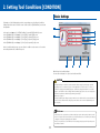
Performing one of the following tasks opens the corresponding screen for setting tool conditions,
Setting method is the same for all of the screens. In this section, the [Edit Conditions] screen is used
for explanation.
1
•In the main screen (Æpage 9), click [Edit Conditions] to open the [Edit Conditions] screen
•In the [Edit Media List] screen (Æpage 16), click [Edit] to open the [Edit] screen
•In the [Edit Media List] screen (Æpage 16), click [New] to open the [New] screen
•In the [Edit Media List] screen (Æpage 16), click [Copy] to open the [Copy] screen
•In the [Edit Media List] screen (Æpage 16), click [Load] to open the [Load] screen
3
4
5
6
2
In the tool condition setting screens, you can edit a tool condition or create a new one. You can also
run a cutting test under the condition that you set.
7
8
9
10
Make the basic tool condition settings.
You can set the cutter type, force, speed, acceleration, and offset.
CAUTION
· Although installing the controller also installs a standard condition setting file, optimal settings may differ
depending on the use environment, the types of media, applications, and other factors. To set values, see
"Guideline for Settings (for Each Media)" (page 12), "Guideline for Settings (When Plotter Pen is Selected)"
(page 12), and "Guideline of Offset Setting (for Each Cutter Blade)" (page 12). Be sure to run a cutting test to
determine the optimal tool condition before performing actual cutting.
Æ"Cut Test" on page 14
· Clicking [OK] directly after editing the settings overwrites the tool condition under the current media name. To
create a new tool condition with the settings that you have edited, enter a new name in [Media Name] and
then click [OK].
Reference
· Smaller values for the speed and the acceleration require longer cut time, but the quality is stable. Set small
values for the speed and the acceleration when you cut wide media because such media may move during a
cutting process and good cut quality may not be obtained.
· When you use a plotter pen, set the FORCE to the lowest setting to prolong the pen life. Adjust the speed so
there will be no faint lines.
11
2. S e t t i n g To o l C o n d i t i o n s [ C O N D I T I O N ]
1
Displays the name of the tool condition that is currently selected. To
save a tool condition as a new one, enter a new file name here.
ÆMedia Name (page 16)
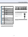
Guideline for Settings (When Plotter Pen is Selected)
Media Name
2
Tool
Specify the part no. of the cutter blade, or the pen.
Water-based fiber-tip pen
Oil-based ballpoint pen
3
Force
4
5
Speed
Accel
Set the force of the cutter or the pen.
Setting range
Part no.
KF7000 Series
KB700-BK
Force
10 ~ 12
25 ~ 28
1 ~ 48
Set the move speed of the tool.
Setting range
What is Offset
1 to 105 cm/sec.
It will adjust the difference between the tip of the blade in the plunger
and the center of the plunger. There are standard adjustment values
for each cutter blades. Fine adjustment will be made to that standard
values here. (Adjustment will be made with standard value as 0.)
Set the acceleration of the tool.
Setting range
1~8
6
Offset
Fine-adjust the difference between the tip of the blade and the center of
the plunger. Set this value based on the type of the cutter blade that you
use.
ÆWhat is Offset (page 12)
ÆGuideline of Offset Setting (for Each Cutter Blade) (page 12)
7
About the blades
Displays detailed information on the cutter blade and the plunger of the
tool that is currently selected.
8
Advanced
Displays advanced setting items.
ÆAdvanced Control of Tool Behavior (page 13)
9
OK
Saves the set content as the current media name and closes the tool
condition setting screen. To newly save it, enter the optional file name
into media name.
Cancel
Cancels the settings and closes the tool condition setting screen.
10
Pen type
For the Pouncing, specify the distance (length) of 1 to 99mm, which
allows the tool to go down.
Guideline of Offset Setting
Refer to the Cutter Blade Manual.
Guideline for Settings
Refer to the Cutter Blade Manual.
12
Speed
(cm/sec.)
30
60
Acceleration
4
4
2. S e t t i n g To o l C o n d i t i o n s [ C O N D I T I O N ]
Advanced Control of Tool Behavior
Specify the tool to be used.
1
1
2
Assign Tool
Distance Adjust
2
3
3
Tangential
Mode*2
Tool 1
The tool attached in backward position of the
holder is used.
Tool 2*1
The tool attached on the station is used.
Tool 3
The tool attached in forward position of the holder
is used. This setting is used when cutting off the
media completely with the backing sheet (when
cutting them out).
Adjust the difference between the data and the line of actual cutting
or plotting that occurs due to the material or thickness of the media. In
the vertical axis (Y) and the horizontal axis (X) respectively, specify the
percentage to use for the adjustment.
Off
Adjustment is not performed.
On
Adjustment is performed.
Setting range
-2.00 ~ +2.00 %
Use this function to cut media whose thickness is equal to or greater
than 0.3 mm.
Off/Mode1/Mode2:ÆWhat is Tangential Mode (page 14)
Setting range
4
[Overcut (Start, End)] 0.0 to 0.9 mm
[Initial Down Force] 0 to 20
Specify whether to perform full line or dashed (perforated) line cutting.
ÆCut Line Pattern (page 14)
4
5
5
Make advanced tool condition settings based on the property of the media that you use.
Cut Line Pattern
Simple
Off
Full line cutting is performed.
On
Dashed (perforated) line cutting is performed.
When setting to On, you can either select a pattern
from 0 to 7 or set an arbitrary pattern (User).
Hides advanced setting items.
*1: Available only when you use a plotter with the 2 pen option.
*2: For FC8000, it appears “Tangent Emulation” on the screen.
CAUTION
· For the setting of cut line pattern, normally use the default value of off.
· For cutting by using the settings in [Cut Line Pattern] (other than [Off]), use Tool 3. Unlike normal media
cutting (half cutting), cutting with a perforated pattern (cutting out) will damage the cutting mat and may affect
the quality of normal cutting. Therefore, do not use Tool 1 for cutting with a perforated pattern.
· When Tool 1is used, a fee will be charged for replacement of the cutting mat that is damaged for cutting with
a perforated pattern.
· For the Pouncing, be sure to use the Tool 1. Using the Tool 3 may possibly damage the plotter.
13
2. S e t t i n g To o l C o n d i t i o n s [ C O N D I T I O N ]
Cut Test
What is Tangential Mode
The blade does not rotate smoothly when cutting media whose thickness is equal to or greater than 0.3 mm and
the start and end points may not match or the corners cannot be cut finely. Tangential Mode enables you to cut
thick media finely by fine-controlling the movement of the tool during a cutting process.
For both Mode1 and 2, you can specify the overcut lengths (extra cut lengths) for the start and end points, from 0.0
to 0.9 mm.
In addition, when cutting thick media, the cutter blade may not be able to go down deep in the media at the
beginning of the cutting even if the force required to the cutting is set, and there may be uncut portion left at the
start point. By setting initial down force, tool down is performed with the combined force of cutting force and initial
down force only at the start point and, therefore, the media is cut properly from the start point.
For both Mode1 and 2, the possible values for [Initial Down Force] are from 0 to 20.
Mode1
Overcuts at the start and end points as well as the sharply angled corners to prevent any
uncut portion from being left. At the sharply angled corners, the blade is raised to the
surface of the media and made rotate before it is lowered again so that sharp cutting can be
realized.
Mode2
Overcuts only at the start and end points. The blade is raised to the surface of the media and
made rotate only at the start point. Because the control in this mode is simpler than that in
Mode1, you can use this mode to reduce the cut time.
2
3
4
1
Run cutting tests to determine if the media is cut properly under the tool condition that you set.
Cut Line Pattern
When [Cut Line Pattern] is On, the media is perforated at the interval that you set. If the length of the part that is
left uncut is too short, the cut object can easily be cut off. In the case where the object is cut off during the cutting
process, set a value that specifies a longer uncut length.
You can select a pattern from the following eight predefined patterns or set an arbitrary pattern by selecting [User].
Type No.
Uncut length for cutting distance of 8 mm
0
0.15 mm
1
0.20 mm
2
0.25 mm
3
0.30 mm
4
0.35 mm
5
0.40 mm
6
0.45 mm
7
0.50 mm
User
Reference
· The tool condition is set appropriately if the media is cut off completely and a slight trace left on the backing
sheet. Readjust the settings if any uncut portion exists on the media or the backing sheet is cut. Also readjust
the blade length of the cutter (ÆChapter 2 "Preparing to Cut" in User's Manual).
· Some of the buttons are assigned keyboard shortcuts. The shortcut keys are as follows:
−[Test for force]→[F9]
−[Test for cutter offset]→[Shift] + [F9]
−[Cut Test]→[F8]
Up
Specify the length of the part to be left uncut. The possible values are
from 0.1 to 10.0 mm.
Cut
Specify the length of the part to be cut. The possible values are from
0.1 to 100.0 mm.
Once the pattern is selected, make the following setting as necessity.
Up Mode
Specify whether to raise the tool totally at the uncut part (Up) or to perform the cutting with
reduced force (Force).
Up Force
If you set [Up Mode] to [Force], specify the cutting force at tool up. The possible values are
from 1 to 48.
14
2. S e t t i n g To o l C o n d i t i o n s [ C O N D I T I O N ]
Test Cutting Patterns
Click this key and then use the keyboard to move the tool to the position
at which the you want to cut the test pattern.
1
2
Position (Use
Keyboard)
Test for force
Up/down/left/right
Press one of the [←↑↓→] keys on the keyboard.
High-speed
movement
Press the [Ctrl] key and one of the [←↑↓→] keys
on the keyboard at the same time.
Skew
Press the up/down arrow key and the left/right
arrow key at the same time. For example, [←] and
[↑] or [↓] and [→].
Cut Test (once with the original
value)
1cm
1cm
Runs three cutting tests by changing the cutting force by 1. The tests are
performed with the value that you set and the values that are increased
or decreased by 1 from the original value.
3
Test for cutter
offset
Runs three cutting tests by changing the offset value by 1. The tests are
performed with the value that you set and the values that are increased
or decreased by 1 from the original value.
4
Cut Test
Runs one cutting test under the tool condition that you set.
ÆTest Cutting Patterns (page 15)
ÆHow to Check Offset (page 15)
Test for force/Test for cutter offset (three times with the original
value and ±1)
-1
Original
value
+1
How to Check Offset
Check if the offset value is set correctly by using the following information as a reference:
Not enough adjustment. Increase the offset value.
Optimal offset value.
Too much adjustment. Decrease the offset value.
15
3. Managing Media List
3
4
5
6
7
8
9
1
2
10
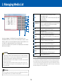
In the main screen (Æpage 9), click [Edit Media List] to open the [Edit Media List] screen.
In the [Edit Media List] screen, you can create a new tool condition and delete, replicate, or edit the
existing tool conditions. You can also load settings from the plotter or assign a Condition No. (1 to 8)
to a condition. The condition with a Condition No. can be called in the plotter.
You can save a tool condition as a file to any location on your computer (export) or load a setting file
that have been saved (import).
CAUTION
· Although installing the controller also installs a standard media list (a list of tool conditions), optimal settings
may differ depending on the use environment, the types of media, applications, and other factors. Be sure to
run cutting tests and set the optimal tool condition before performing actual cutting.
1
List
Lists media names and the corresponding tool conditions.
Click a condition to select it.
To select multiple conditions, click them while pressing the [Ctrl] or [Shift]
key on the keyboard.
ÆMedia Name (page 16)
2
Condition No.1 to
8
Assign a Condition No. (1 to 8) to the tool condition that is currently
selected. The condition with a Condition No. can be called in the plotter.
Select a tool condition from the list and click one of the buttons:
[Condition No.1] to [Condition No.8].
3
New
Opens the [New] screen.
Æ2. Setting Tool Conditions [CONDITION] (page 11)
4
Edit
Open the [Edit] screen.
Æ2. Setting Tool Conditions [CONDITION] (page 11)
5
Delete
Deletes the tool condition that is currently selected.
The tool condition to which a Condition No. (1 to 8) is assigned cannot
be deleted.
6
Copy
Opens the [Copy] screen.
Æ2. Setting Tool Conditions [CONDITION] (page 11)
7
Load
Loads tool conditions from the plotter and opens the [Load] screen.
Æ2. Setting Tool Conditions [CONDITION] (page 11)
8
Import
Loads the media list that is stored in your computer.
ÆImport/Export Functions for Tool Conditions (page 16)
9
Export
Saves the tool condition that is currently selected to a location on your
computer.
ÆImport/Export Functions for Tool Conditions (page 16)
10
Close
Closes the [Edit Media List] screen.
Media Name
The controller manages tool conditions by using media names. This is because the media to be used determines
the tool condition. Note that, however, optimal condition settings for the same media may differ depending on the
use environment or the shape of the image to be plotted. Therefore, saving a tool condition under a file name that
consist of the media name and additional description by which the variation of the settings can be understood may
help to find the settings that are close to the optimal condition.
· On Windows Vista/7/8, the media list is saved for each logged-on user. If you want to use the same media list
as before, log on as the same user.
· On Windows XP, changes made to a media list are saved when you exit the controller as long as you are
logged on as administrator. If you are logged on as user other than administrator, the changes are not saved
when you exit the controller.
Reference
Up to 100 tool conditions can be saved to the list. If you try to save tool conditions that exceed the limit of 100,
a message will appear. In that case, you should delete unnecessary setting files.
16
3. M a n a g i n g M e d i a L i s t
Import/Export Functions for Tool Conditions
By using these functions, you can save a tool condition that is set in the controller to any location on your computer
or load a tool condition that has been saved to your computer. You can also save multiple tool conditions as a
single file and load the file. The extension of the files that can be imported or exported is ".GMIE".
Export
1. Select a condition from the media list and click [Export].
2. Enter the file name in the [Save As] screen and specify the location to which you save
the condition.
3. Click [Save] to save the setting file.
Import
1. Click [Import].
2. Select the file to load in the [Open] screen.
3. Click [Open] to load the condition and add it to the bottom of the list.
17
4. Tools Setting [TOOL]
1
1
8
2
9
3
2
10
4
5
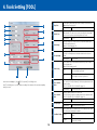
Step Pass
Setting range
Offset Force
3
Offset Angle
6
4
Tool Up Height
13
1 ~ 40
Specify the angle to use as the reference to determine if blade angle
control should be performed.
ÆWhat is Offset Angle (page 19)
Setting range
12
0 ~ 20
Specify the cutting force when the direction of the blade is set in the
initial operation. The value is also used as the cutting force when blade
rotation control is performed when tangential mode is used.
Setting range
11
0 to 60 degrees
Specify the height by which the tool is raised to the surface of the media
(Tool Up). Set how high the tool should be raised from the reference
height.
Setting range
0.0 to 5.0 mm
Specify whether to store the data in the buffer memory and sort them
before plotting starts.
ÆWhat is Data Sorting (page 19)
7
5
14
Set the units by which data is processed. Normally, set the value to [0].
ÆWhat is Step Pass (page 19)
Data Sorting
15
In the main screen (Æpage 9), click
[TOOL] to open the [Tools Setting] screen.
In the [Tools Setting] screen, you make advanced settings for the behavior of the tool and how plotting
data is processed.
6
Tool 1-2 Offset
ADJ.*1
Area
Off: Area sorting is not performed.
On: Area sorting is performed.
Tool
Off: Sorting for each tool is not performed.
On: Sorting for each tool is performed.
If there is any difference in the drawing, adjust the distance between
Tool 1 and Tool 2. Click [Test Pattern] to cut the test pattern based on the
adjusted setting.
ÆTool 1-2 Offset ADJ./Tool 1-3 Offset ADJ. (page 19)
Setting range
7
Tool 1-3 Offset
ADJ.
Setting range
8
Tool Up Speed
-3.0 mm to +3.0 mm
Adjust the distance between Tool 1 and Tool 3.
Click [Test Pattern] to cut the test pattern based on the adjusted setting.
ÆTool 1-2 Offset ADJ./Tool 1-3 Offset ADJ. (page 19)
-3.0 mm to +3.0 mm
Specify the move speed of the tool when the tool is raised.
Setting range
Auto, 10/20/30/40/50/60 cm/sec.
Specify whether the tool conditions can be set or edited from the control
panel of the plotter and from the controller.
9
18
Condition Priority
Manual
Conditions can be set/edit only from the control
panel.
Program
Conditions can be set/edit from either the control
panel or the controller.
4. To o l s S e t t i n g [ T O O L ]
10
Tool Select
Command
What is Offset Angle
Specify whether to enable or disable tool replace commands ("J" in GPGL, "SP" in HP-GL), independently from the setting in [Condition Priority].
Enabled
Enables tool replace commands.
Disabled
Disables tool replace commands.
The plotter analyzes the cutting data to determine if blade angle control should be performed based on the
change amount of an angle. Angle control is performed when the change amount of an angle is equal to or more
than the value that you set in [Offset Angle]. If a small value is set, angle control is performed frequently for some
image shapes and, therefore, the quality is improved but cut time becomes longer. On the other hand, a large
offset angle value reduces the cut time but an image different from the intended one may be cut.
Specify the position at which initial adjustment of the blade direction is
done.
ÆWhat is initial adjustment of the blade direction (page 20)
11
12
Initial Blade
Tool Up Move
2mm Below
The initial adjustment of the blade direction is done
at 2 mm below the start point of the cutting.
Outside
The initial adjustment of the blade direction is done
outside of the cutting area.
What is Data Sorting
This is a function to store plotting data in the buffer memory and arrange the process order so that more efficient
plotting can be done.
By the Area sort, the process order is arranged so that the movement distance of the tool in the feed direction
becomes the shortest at tool up.
By the Tool sort, the process order is arranged so that plotting with Tool 1 is performed last if the data for Tool 1
and Tool 2 are mixed in the plotting data. Available only when 2 pen (Option) is selected.
If [Data Sort] is set to on, the time before the plotting starts becomes longer because data is temporarily
accumulated in the buffer memory.
Set the data sort in the controller to off when the data that has already been sorted with the application or driver
software is used for plotting.
Specify whether the plotter moves the tool each time it receives the
coordinates or directly moves the tool to the last coordinates when the
controller sends instructions in series to the plotter to raise and move the
tool.
Enabled
The tool moves along the coordinates received.
Disabled
The tool moves to the last coordinates.
Tool 1-2 Offset ADJ./Tool 1-3 Offset ADJ.
Click this key and then use the keyboard to move the tool to the position
at which the you want to cut the test pattern.
13
14
15
Position
(Use Keyboard)
Up/down/left/right
Press one of the [←↑↓→] keys on the keyboard.
High-speed
movement
Press the [Ctrl] key and one of the [←↑↓→] keys on
the keyboard at the same time.
Low-speed
movement
Press the [Shift] key and one of the [←↑↓→] keys
on the keyboard at the same time.
Skew
Press the up/down arrow key and the left/right
arrow key at the same time. For example, [←] and
[↑] or [↓] and [→].
OK
Saves the settings and closes the [Tools Setting] screen.
Cancel
Cancels the settings and closes the [Tools Setting] screen.
Specify how much Tool 2 or Tool 3 is moved based on the Tool 1.
•Tool 1-2 Offset ADJ.
Adjust the positions of Tool 1 and Tool 2 in the plotter with 2 pen option. Use this setting when there is a difference
between drawings by the two tools. For adjustment values X and Y, see the figure below.
•Tool 1-3 Offset ADJ.
Adjust the positions of Tool 1 and Tool 3 Use this setting when there is a difference between drawings by the two
tools. For adjustment values X and Y, see the figure below.
1. Correctly set the Cutter plunger or 2 Plotter pens, and turn on the power source.
2. Make sure that the plotter is in ready status.
3. Open the [Tools Setting] screen of the controller.
4. Click the [Position (use Keyboard)], and then use the keyboard of PC to move the Tool carriage to the position at
which you want to cut the [+] (test pattern). (For both X and Y directions, move it to 50mm and over inside of the
plotting area.)
5. Click [Test Pattern] to cut the test pattern.
6. Measure the distance between 2 tools through the test pattern plotted.
*1: Available only when you use a plotter with the 2 pen option.
Feed direction of media
What is Step Pass
A set of units by which cut data is processed is called Step Pass. If set, the cutting is performed by skipping blade
control for the data that is less than the specified value. Set this setting when the space is extremely small in the
cut data, to reduce cut time while performing stable blade rotation control. The smaller the value is, the finer blade
control is performed and, therefore, the quality is improved but cut time becomes longer. Normally, set the value to
[0]. One unit is the distance that you set [Step Size] in [GP-GL] in the [Interface] screen (Æpage 23).
19
Distance adjustment
value X
Distance
adjustment
value Y
Cross shape drawn with
Tool 2 or 3
Cross shape drawn with
the physical pen 1
The pen's starting
position
Y
X
4. To o l s S e t t i n g [ T O O L ]
As an example, in the figure above, it needs to move in negative directions for both X and Y directions, so both of
the adjustment values will be negative values.
7. Repeat the procedures 5 to 6 until the difference between tools disappears.
What is initial adjustment of the blade direction:
Initial adjustment of the blade direction is an operation that softly puts the blade on the media to align the blade
directions right after turning on the power source of plotter or after changing the condition settings.
20
5. Setting Area Parameters [AREA]
1
3
2
4
5
1
Scale
Opens the [Scale] screen.
ÆScale Setting (page 21)
2
Mirror
Opens the [Mirror] screen.
ÆMirror Setting (page 21)
3
Expand
Opens the [Expand] screen.
ÆExpand Setting (page 22)
4
Area
Opens the [Area] screen.
ÆArea Setting (page 22)
5
Close
Closes the [Area Parameters] screen.
Scale Setting
In the main screen (Æpage 9), click
[AREA] to open the [Area Parameters] screen.
In the [Area Parameters] screen, you set values regarding to the plotting area.
CAUTION
· Although plotting can be performed at a position on and outside of the push rollers when the expand limit is
set to a positive value in [Set Expand Limit] under [Expand], some media may not be fed properly because
the push rollers move on the plotted surface.
Plotting is performed with the enlarged/shrunk size.
Scales that can be set are 1/8, 1/4, 1/2, 1, 2, 3, 4, 5, 6, 7, and 8 (multiplications).
· When the expand limit is set to +8 mm or higher, Initial may be performed outside the loaded media,
Mirror Setting
regardless the setting in [Initial Blade] in the [Tools Setting] screen (Æpage 18) In this case, caution is
required because the blade may be damaged.
Reference
· When turning mirror mode on or off, the Area settings are initialized.
· You should set a Expand setting before sending the plotting data to the plotter, When you change the setting,
the plotter clears data in the buffer memory to perform initial settings.
· In [Area], set the values in [Set Upper Right] and [Set Lower Left] so that the distance between them is equal
to or larger than 5 mm.
Sets the mirror mode that reverses the origin point and vertical and horizontal coordinate axes.
Selecting On enables the mirror mode.
When the plotter power is turned off, the mirror mode is also turned off.
21
5. S e t t i n g A re a P a r a m e t e r s [ A R E A ]
Expand Setting
Area Setting
Broaden or narrow the width of the plotting area.
When the initial value ([Default]) is used, the width expands to the internal edge of the push rollers (See
the figure below).
Select [Set Expand Limit] and enter a negative value to obtain narrower width or enter a positive value
to obtain broader width than when the initial value is used.
The possible values are from -10.0 to +10.0 mm.
Set the plotting area that you want. The square specified by the points that are set by using [Set
Upper Right] and [Set Lower Left] is the plotting area.
This setting is used when, for example, you want to plot on a free area on the plotted media.
To set a plotting area, perform the following procedure:
1. Click [Position (Use Keyboard)].
2. Press one of the [←↑→↓] keys on the keyboard to move the tool to the position that you want to
set as the lower left point and click [Set Lower Left].
3. Press one of the [←↑→↓] keys on the keyboard to move the tool to the position that you want to
set as the upper right point and click [Set Upper Right].
To use the setting area for use in media setting, select [Default].
Push roller
Edge position
<For rear loading/sheet>
It will only cut
within this area
Upper right set
position
Lower left set position
Image already cut
22
6. Interface Setting [I/F]
1
1
Command
2
Specify the plotting command. Select one of GP-GL command, HPGL command or AUTO. Select [Auto] to automatically determine
the command. (User’s Manual Chapter 11 “Setting of controls from
Computer”)
Step Size
Specifies the movement distance per step. Select
from 0.100mm, 0.050mm, 0.025mm, and 0.010mm.
Command ":",";"
Enables/disables Command ":",";".
Command "W"
Specifies whether to raise the tool or keep the
current tool state before moving the tool to the
start point when "W", instruction to draw an arc,
is issued. When [Tool Down] is selected, the tool
moves, keeping the same state (raised or lowered)
as one right before the instruction is issued. When
[Tool Up] is selected, the tool is raised and then
moved. This setting is valid only when the tool is a
cutter blade.
Origin Point
Sets the lower left or center of the plotting area as
the origin point.
Model Emulated
Sets the response to the "OI" command. Select
[7550] to set 7550 as the value of the response to
"OI" command. Select [7586] to set 7586 as the
value of the response to "OI" command.
Circle Resolution
Specifies whether to automatically set the
resolution or use the fixed value of 5 degrees when
the instruction to draw an arc is issued.
3
2
4
GP-GL
5
Click
[I/F] on the main screen (Æpage 9) to open the [Interface] screen.
The settings related to Interface can be done in the [Interface] screen.
3
HP-GL
CAUTION
4
5
When the controller is started from the driver software, select the GP-GL command.
23
OK
Saves the settings and closes the [Interface] screen.
Cancel
Cancels the settings and closes the [Interface] screen.
7. ARMS Setting [ARMS]
Registration Marks Setting
ARMS (Advanced Registration Mark Sensing System) is a system that automatically reads registration
marks. The ARMS functions enable you to cut printed material more precisely.
The main ARMS functions include 4points (2 axes warp) adjustment, multiple registration mark
adjustment, segment area adjustment, and automatic scanning of the registration marks. In
the controller, you can configure and perform 4points (2 axes warp) adjustment, segment area
adjustment, and automatic scanning of the registration marks.
Settings for ARMS are made in [Registration Marks] on the main screen (Æpage 9), the [Registration
Mark Settings] screen (Æpage 25), and the [ARMS Setting] screen (Æpage 26).
CAUTION
1
· ARMS is a function to align the cutting position with the print position as much as possible and does not
guarantee an accuracy where the media is cut at the same print position and in the same size as defined by
data.
2
3
· Unlike plotters (drawing machines), printers generally do not guarantee accuracy in terms of the print position
and the size. In particular, when a laser printer and sheet media are used, the print may be distorted
considerably and you may not be able to obtain a proper cutting result even if adjustment is made to the print
by using the registration marks.
4
Registration
Marks
2
Mark Auto Scan
Check this if you want to scan and read the registration marks
automatically when the cutting starts. This setting is available when
[Registration Marks] is checked.
ÆMark Auto Scan (page 25)
3
Mark Distance
Specifies the distance between registration marks by using the vertical
axis (Y) and the horizontal axis (X). Check the distance in the application
software that you used to set the registration marks.
4
RM Settings
Opens the [Registration Mark Settings] screen.
ÆRegistration Mark Settings (page 25)
5
Read Marks
Starts reading of the registration marks.
ÆMark Auto Scan (page 25)
1
24
5
Check this if you want to use registration marks to cut media that has an
image printed. (Registration marks also need to be printed on the media
beforehand.)
ÆWhat is Registration Mark (page 25)
7. A R M S S e t t i n g [ A R M S ]
Settings in the [Registration Mark Settings] Screen
What is Registration Mark
1
A registration mark is a mark to align positions to cut the printed image properly. Set marks around the image
before printing it. The plotter uses a registration mark sensor to read the marks and corrects the position or
distortion of the image before performing cutting. For proper reading of the registration marks, ensure that the
printed image does not go into or around the marks.
2
Mark Auto Scan
This is a function to scan and read the registration marks automatically when the cutting starts. Registration marks
within a certain area from the current position of the tool to the center of the media are detected. However, marks
may not be detected if there is no mark near the area. In such case, turn [Mark Auto Scan] off*, move the tool
above the first registration mark (Registration Mark located at the position painted with green on the drawing in
main screen of the controller), and then click [Read Marks].
*If you start the controller from the Start menu, registration marks can be read by using [Read Marks], regardless
the setting in [Mark Auto Scan].
3
4
5
3
7
In the main screen (Æpage 9), click [RM Settings to open the [Registration Mark Settings] screen.
In this screen, you set detailed conditions necessary to read registration marks, including the number
and the shape of the mark.
CAUTION
To perform a segment area adjustment (Æ"Adjustment by Using Registration Marks" on page 26), the direction
where the intermediate registrations placed must be the same as the feed direction. So, load the media
accordingly. Intermediate registration marks that are in the moving direction of the cutter blade cannot be read.
25
1
Mark Scan Mode
Set the number of registration marks to scan.
ÆAdjustment by Using Registration Marks (page 26)
2
Mark Type
Select the shape of the registration mark.
3
Step
When [Area] is set in [Mark Scan Mode], specify the distance by which
each intermediate registration mark is placed.
Setting range
100.0 mm to 10000.0 mm
Specify the length of the registration mark from the corner to the end.
4
Length
5
Thickness
6
7
OK
Saves the settings and closes the [Registration Mark Settings] screen.
Cancel
Cancels the settings and closes the [Registration Mark Settings] screen.
Setting range
5.0 mm to 20.0 mm
Specify the thickness of the registration mark.
Setting range
0.3 mm to 1.0 mm
7. A R M S S e t t i n g [ A R M S ]
Settings in the [ARMS Setting] Screen
Adjustment by Using Registration Marks
The plotter reads the registration marks to perform alignment of the origin point, adjustment of the vertical distance,
and correction of the distortion. Depending on the number of marks, the adjustment method may differ.
Mark Scan Mode
2points
3points
4points
Area (segment area
adjustment)
Adjustment to be done
Adjusts the horizontal distance and the tilt. Registration marks at lower left and
lower right are read and the distance between these two marks is adjusted so as
to be the same distance as you set in the [X] of [Mark Distance] (Æ"Registration
Marks Setting" on page 24).
Adjusts the vertical and horizontal distance and the tilt. Registration marks at
lower left + lower right and lower left + upper left are read and the distances
between each pair of the marks are adjusted so as to be the same distances as
you set in the [X] and [Y] of [Mark Distance] (Æ"Registration Marks Setting" on
page 24).
Registration marks at lower left, lower right, upper left, and upper left are read
and are adjusted to the registration mark positions calculated from the distances
you set in the [X] and [Y] of [Mark Distance] (Æ"Registration Marks Setting" on
page 24).
For a long image, like one whose length in the feed direction is more than 2
m, corrects the distortion produced during the printing process. By using the
intermediate registration marks as boundaries, the image is divided in the feed
direction into several areas and 4points adjustment is performed.
1
3
2
4
5
6
7
In the [ARMS Setting] screen, you set detailed conditions to use the ARMS functions.
In the main screen (Æpage 9), click
[ARMS] to open the [ARMS Setting] screen.
1
Paper-Weight
<For rear loading/sheet>
2
Axis Alignment
Tool
Set whether to hold down the media with the paper-weight when the
sensor reads the registration marks.
Off
The paper-weight will not be used.
On
The paper-weight will be used.
Set the tool that is used for manual axis alignment. Select from [Loupe]
and [Light Pointer].
ÆAxis Alignment (page 27)
Click this key and then use the keyboard to move the tool to the position
at which the you want to cut the test pattern.
Upper left
Upper right
Lower left
Lower right
3
4
26
Position
(Use Keyboard)
Sensor Adjust
Up/down/left/right
Press one of the [←↑↓→] keys on the keyboard.
High-speed
movement
Press the [Ctrl] key and one of the [←↑↓→] keys on
the keyboard at the same time.
Skew
Press the up/down arrow key and the left/right
arrow key at the same time. For example, [←] and
[↑] or [↓] and [→].
Automatically adjusts the scanning level of the sensor that scans
registration marks. Click [Execute] to start the automatic adjustment.
ÆSensor Adjust (page 27)
7. A R M S S e t t i n g [ A R M S ]
5
Sensor Offset
ADJ.
Adjust the position of the sensor that scans registration marks.
ÆSensor Offset ADJ. (page 27)
6
7
OK
Saves the settings and closes the [ARMS Setting] screen.
Cancel
Cancels the settings and closes the [ARMS Setting] screen.
•Detect the Registration Mark for Adjustment, and enter the Value
When the Registration Mark is already cut on the Media or when the Media where Adjustment Registration Mark is
cut is used using the [Test Pattern], take the following procedures.
1. Load the media with adjustment registration mark in the plotter.
2. Open [ARMS Setting] screen of controller.
3. Click [Position (use Keyboard)], and use the Keyboard of PC to move the Tool to the area at which you want to
start scanning the Registration Mark.
Feed direction of medi
Axis Alignment
In Axis Alignment, you adjust the tilt of the Axis by using alignment marks (such as grits and registration marks)
for 2points, 3points, or 4points as references. In addition you can adjust the distance by entering the distance
between each points. Use the loupe or the light pointer for the tool to align the tool to the position of each point.
Use media that has drawings (alignment marks such as grits and registration marks) required to determine the X/Y
axes and the origin point.
For more information on the axis alignment procedure, see Chapter 6 "Manual Position Adjust" in User's Manual.
X
Y
Align the tool to this area
4. Click [Scan] of [Sensor Offset ADJ.] to scan the Registration Mark for Adjustment, and plot the Registration
Mark for comparison.
Sensor Adjust
Feed direction of medi
Scan level (threshold value between the media background color and registration mark) of the sensor scanning the
registration mark is automatically adjusted. Sensor is adjusted to scan the registration mark written in black lines
on white background. Readjust the scan level of the sensor depending on the color and gloss of the media. If it is
hard to adjust the level automatically due to media characteristics, adjust the scan level of the sensor manually.
When you want to revert the sensor level back to the default, use the control panel of the plotter. For more
information on the sensor level adjustment procedure, see Chapter 5 "ARMS (Advanced Registration Mark Sensing
System)" in User's Manual.
Sensor Offset ADJ.
Sensor to scan the registration mark is positioned away from the tip of the tool (pen tip). Therefore, it is necessary
to adjust the coordinate values of the scanned registration mark so it will match with the cutting position.
Specify how much the cross shape, which was plotted after scanning, should be moved based on the cross shape
to be scanned.
Distance adjustment value Y
Distance
adjustment
value X
The cross shape plotted
after scanning
X
Y
5. Using the scanned Registration Mark for Adjustment, measure the distance of how much the comparison
registration mark needs to be moved so both will overlap, and record the value. As an example, in the figure
above, it needs to move in negative directions for both X and Y directions, so both of the adjustment values will
be negative values.
6. Enter the values, which were measured in the above 5, into each X/Y as the adjustment value.It is able to set
for both X and Y in the range from -3.0mm to +3.0mm.
•Plotting Registration Mark for Adjustment
When Registration Mark is not plotted on the media, first plot the Registration Mark. Then proceed to the step of
"Detect the Registration Mark for Adjustment, and enter the Value".
1. Load white media.
2. Set the water-based fiber-tip pen on the tool holder.
3. Open the [ARMS Setting] screen of controller.
4. Click [Position (use Keyboard)], and use the Keyboard of PC to move the Tool to the position at which you want
to cut the Registration Mark (test pattern).
5. Click [Test Pattern] of [Sensor Offset ADJ.], and plot the Adjustment Registration Mark.
27
8. Media Setting [MEDIA]
1
2
3
7
4
8
5
1
Page Length
2
Cross Cut Force
3
10
11
Panel Cutting
Specify the cutting force for cross cut. Set a smaller value for thin media
and a larger value for thick media.
On
Panel Cutting is available.
Off
Panel Cutting is not available.
Setting range
1.0 to 2000.0cm
Roll Set
5
Feed Speed
Specify the feed speed for the Pre Feed. Normally use [Normal].
Set this setting to [Slow] when heavy or slippery media is used.
ÆWhat is Pre Feed (page 29)
7
Initial Feed
Auto Pre Feed
Specify whether pre feed should be performed for the length specified
by [Page Length] when the set lever is raised after the media is loaded.
ÆWhat is Pre Feed (page 29)
On
Pre feed is performed.
Off
Pre feed is not performed.
When checked, pre feed is performed automatically when the plotting
data is received. The pre feed is performed for the length specified by
[Feed Length].
ÆWhat is Pre Feed (page 29)
Setting range
8
9
AP Mode
Pre Feed
10
11
0.5 to 50.0 m
When checked, the mode for AP (apparel industry) becomes available.
ÆAP Mode (page 29)
Pre feed can be manually started.
Check [Pre Feed], specify the feed length, and click [Start] to perform
pre feed once.
ÆWhat is Pre Feed (page 29)
Setting range
28
1 ~ 48
Check this to cut after dividing by a specified partition length, in order to
prevent skewing of the length.
* Unavailable for FC8000.
ÆFor the Panel Cutting, see page 27.
4
In the main screen (Æpage 9), click
[MEDIA] to open the [Media Setting] screen.
In the [Media Setting] screen, you set values regarding to media.
Be sure to specify a longer length in [Page Length] than the plotting data. Plotting is performed only within the
length specified by the [Page Length].
20.0 to 5000.0cm
Specify the direction in which roll media has been loaded: from the front
or rear of the plotter. Select either [Front] or [Rear].
6
CAUTION
Setting range
Setting range
6
9
Set the length of 1 page when using the roll media.
0.5 to 50.0 m
OK
Saves the settings and closes the [Media Setting] screen.
Cancel
Cancels the settings and closes the [Media Setting] screen.
8. M e d i a S e t t i n g [ M E D I A ]
Panel Catting
* Unavailable for FC8000.
To prevent long skew, utilize partition length when cutting.
•When Panel Cutting is on, the machine will begin by dividing up partition length and continue cutting until one
of the following data breaks appears. When the first partitioned area cut is finished, the machine will move to the
next area, and repeat this until all areas have been cut.
•Data Breaks:
(1) No data sent for a few seconds after finishing cutting. (Time Out)
(2) A feed-related command is set. (GP-GL - F, FS commands, HP-GL - AF, AH, PG commands)
(3) HP-GL - SP0, NR, GP-GL - J0, SO
(4) When commands from data breaks (2) and (3) appear, that command work will begin after the partition
pastern cutting is finished.
•Panel cutting will continue for each piece of data when a data break is caused by a command, even if multiple
pieces of data are sent in before the cutting finishes (even when numerous pieces of panel cutting data are in
the plotter buffer).
•When panel cutting and auto media transfer are both turned on, the machine will ignore automatic media transfer
length settings and continue working with priority of partition length +a minutes ago (with footprints).
•When panel cutting is on, registration marks will not be seen ignored, and copy, initial feed, and cutting area
cannot be changed.
•If 1 piece of data causes the buffer to be full, partition linking will not be possible. Make sure only to send data
that is below the buffer size.
What is Pre Feed
This function prevents the loaded media from slipping by advancing the media by the specified length and then
drawing back to imprint grit roller marks on the media. It also ensures stable media feed operations by acclimating
long media to the operating environment. For roll media, the amount to use for plotting must be pulled out
beforehand. You can let the plotter do this work.
AP Mode
This function is used to connect to a CAD for AP (apparel industry).
Time Out
The media is fed when data is not received within the specified time after finishing
the plotting. Select a value from 0, 1, 2, 3, 5, 10, 20, 30, 60, and 120 seconds.
When [0] is set, the media will not be fed.
Separator GP-GL
Set the command to be used as the separator of data. One sheet is plotted every
time the data is separated. Select a value from - (no separator is set), F, J0, H, and
FS.
Separator HP-GL
Set the command to be used as the separator of data. One sheet is plotted every
time the data is separated. Select a value from - (no separator is set), AF, AH, PG,
NR, SP, IP, SC, IW, PS, DF, and IN.
Space Rear
Specify the space for between the position where plotting data is terminated and
the position for cutting off the media. The possible values are from 7.0 to 30.0 mm.
29
9. Advance [ADV.]
1
1
Language
Selection
Select the language in which menus are shown on the LCD screen in the
control panel of the plotter.
Select from [English], [Japanese], [Deutsch], [Francais], [Italiano],
[Espanol], and [Portugues]. This does not change the display language
of the controller.
2
Length Unit
Select the length unit that is shown on the LCD screen in the control
panel of the plotter. Select from [metric] and [inch]. This does not
change the display unit of the controller.
3
Move Step
Set the movement distance of the carriage and the media when one
of the [Position] keys (
) is pressed. Select from [0.1mm] and
[1.0mm].
5
2
3
6
4
7
8
4
Media Sensor
Specify whether to use the sensor that checks if media is set and
detects the media length (in the feed direction).
Disabled
The sensor will not be used.
Enabled
The sensor will be used.
Specify whether to check if a tool is attached on the station when the
media detection is performed.
9
5
10
In the main screen (Æpage 9), click [ADV.] to open the [Advance] screen.
In the [Advance] screen, you make environment settings for the plotter.
CAUTION
Check Tool*1
6
Fan Power
7
Beep For Key
Ope.
When [Push Roller Sensor] is set to [Disabled], cross cutting cannot be done.
Disabled
The check will not be performed. Be sure to attach
Tool2 on the station before turning the power on.
Enabled
The check will be performed.
Set the air volume of the fan that sucks the media. Normally, select
[Normal]. For thin media, select [Weak].
Specify whether to beep when a key on the control panel of the plotter is
pressed.
Off
Beep will not be generated.
On
Beep will be generated.
Specify whether to use the push roller sensors that detect the width of
the media. Normally, select [Enabled].(ÆChapter 10 "Settings Regarding
Operating Environment" in User's Manual)
8
9
10
Push Roller
Sensor
Disabled
The push roller sensors will not be used.
Inside Disabled*2
The push roller sensors other than ones at the
edges will not be used.
Enabled
The push roller sensors will be used.
OK
Saves the settings and closes the [Advance] screen.
Cancel
Cancels the settings and closes the [Advance] screen.
*1: Available only when you use a plotter with the 2 pen option.
*2: When more than three push rollers are used, the roller sensor(s) in midway will be disabled.
30
10. Option Settings
In the main screen (Æpage 9), click [Option] to open the [Option] screen.
In the [Option] screen, you select the plotter to be controlled by the controller, set the unit to be used
in the controller, initialize the media list, and make other settings. You can also retrieve information
1
2
CAUTION
3
· On Windows Vista/7/8, the media list is saved for each logged-on user. If you want to use the same media list
as before, log on as the same user.
· On Windows XP, you can execute [Restore to default] under [Media List] only when you are logged on as
administrator. When logging on as the users other than those, a message appears and it is unable to return to
the media list of default.
4
5
6
7
8
9
10
31
10. Option Settings
1
Driver (Select)
Specify the plotter for which you want to make settings in the controller.
From the [Select] pull-down list, select the driver for the plotter for which
you want to make settings.
2
Firmware
Displays the firmware information for the plotter corresponding to the
driver that is currently selected.
3
Unit
Specify the length unit to be used in the controller. Select from [mm] and
[inch].
4
Media List
(Restore to
default)
Restores the media list to the default. Click [Execute], and a message
asking if you are sure to restore the media list to the default appears.
Click [OK] to restore to the default.
5
Plotter setting
The settings in the following screens are saved to the computer: [Tools
Setting], [Area Parameters], [Interface], [ARMS Setting], [Media Setting],
[Advance] and the saved settings can be loaded to the controller.
ÆImport/Export Functions in Plotter Setting (page 32)
6
Error Information
Retrieves and displays the error information on the plotter. Click [Execute]
to display the error information. Click [Save] in the [Error Information]
screen to save the information in text file format to the computer.
7
Condition
Information
Retrieves and displays the condition information on the plotter. Click
[Execute] to display the condition information. Click [Save] in the
[Condition Information] screen to save the information in text file format
to the computer.
8
User Name
Specify the user name to be used in the plotter. Enter desired names in
[User1] and [User2].
Click [Upload] to set the names in the plotter.
OK
Saves the settings and closes the [Option] screen.
Cancel
Cancels the settings and closes the [Option] screen.
9
10
Import/Export Functions in Plotter Setting
By using these functions, you can save settings that are set in the controller to any location on your computer
or load the settings that have been saved to your computer. The extension of the files that can be imported or
exported is ".GDS".
32
Export
1. Click [Export].
2. Enter the file name in the [Save As] screen and specify the location to which you save
the settings.
3. Click [Save] to save the settings.
Import
1. Click [Import].
2. Select the file to load in the [Open] screen.
3. Click [Open] to load the settings.
11. Troubleshooting
List of Error Messages
Uninstalling the Controller
The following list describes error messages that may appear in the controller and actions to be taken.
If a problem cannot be solved, contact "Customer Service Contact".
Error message
Action
Try to reboot your computer when the controller does not work properly.
If it the problem persists, uninstall it by following the procedure below and re-install it properly.
For more information on how to install the controller, see "Setup Manual".
Reference
"Communication with
the plotter could not be
established. Please confirm
that the plotter is connected
correctly and that it has been
turned on."
Make sure that the cable is
connected properly.
Make sure that the plotter is
powered on.
ÆSetup Manual
ÆChapter 1 "Assembling and
"Cannot communicate with the
plotter. Turn off the plotter's
power switch, and then turn it
on again."
Turn off the plotter's power
switch, and then turn it on
again.
ÆChapter 2 "Preparing to Cut"
"GITKPRNP.DLL could not
be found, and so the Cutting
Plotter Controller for FC8000
could not be started. Please
reboot your computer or reinstall the Cutting Plotter
Controller for FC8000."
Reboot you computer.
If the problem still exists,
uninstall and then re-install
the controller.
Æ"Uninstalling the Controller" on
"The GITKPRNP.DLL functions
could not be found, and so the
Cutting Plotter Controller for
FC8000 could not be started.
Please reboot your computer
or re-install the Cutting Plotter
Controller for FC8000."
Reboot you computer.
If the problem still exists,
uninstall and then re-install
the controller.
Æ"Uninstalling the Controller" on
"Registration mark reading
has failed. Confirm that the
Mark Distance set is correct.
Confirm that the Mark Type
set is correct."
Check the settings in
[Registration Marks]. Make
sure that the media is loaded
properly.
Æ7. ARMS Setting [ARMS] (page
24)
ÆChapter 2 "Preparing to Cut"
"Did not read the registration
marks. The print and cut
positions may not line up. Cut
anyway?"
Read the registration marks
before cutting when you cut
printed material.
If you are not using
registration marks, set
[Registration Marks] to off.
Æ7. ARMS Setting [ARMS] (page
24)
ÆChapter 5 "ARMS (Advanced
Registration Mark Sensing
System)" in User's Manual
1.
2.
3.
Stop the controller if it is running.
From the Start menu, open the Control Panel.
Click [Program].
(If you use the Classic view to see the Control Panel on Windows Vista/7 or if you use Windows XP,
skip this step.)
4. Click [Programs and Features] (on Windows XP, [Add or Remove Programs]).
5. Select [Cutting Plotter Controller for FC8000] and click [Uninstall] (on Windows XP, [Remove]).
6. Complete the uninstall by following the instructions on the screen.
Connection" and Chapter 2
"Preparing to Cut" in User's
Manual
in User's Manual
page 33
ÆSetup Manual
page 33
ÆSetup Manual
in User's Manual
33
12. Index
A
E
M
About.......................................................10
About the blades.....................................12
Accel.......................................................12
ADV............................................................9
Advance..................................................30
Advanced................................................12
Advanced Control of Tool Behavior.........13
AP Mode..................................................28
AREA.........................................................9
Area.........................................................21
ARMS.........................................................9
ARMS Setting....................................24, 26
Assign Tool..............................................13
Auto Pre Feed..........................................28
Axis Alignment Tool.................................26
Edit..........................................................16
Edit Conditions..........................................9
Edit Media List...........................................9
Error Information......................................32
Error Messages.......................................33
Expand....................................................21
Export......................................................16
Main Screen..............................................9
Managing Media List...............................16
Mark Auto Scan.......................................24
Mark Distance.........................................24
Mark Scan Mode.....................................25
Mark Type................................................25
MEDIA.......................................................9
Media List (Restore to default)................32
Media Name............................................12
Media Sensor..........................................30
Media Setting..........................................28
Mirror.......................................................21
Move Step...............................................30
F
Fan Power................................................30
Features.....................................................6
Feed Speed.............................................28
Firmware..................................................32
Force.......................................................12
N
GP-GL......................................................23
O
Offset.......................................................12
Offset Angle.............................................18
Offset Force.............................................18
Operation Environment..............................6
Option......................................................10
Option Settings........................................31
Origin.......................................................10
H
Cancel.......................................................9
Check Tool...............................................30
Close.........................................................9
Command................................................23
Condition Information..............................32
Condition No............................................16
Condition Priority.....................................18
Copy........................................................16
Cross Cut.................................................10
Cross Cut Force......................................28
Cut.............................................................9
Cut Line Pattern.......................................13
Cut Test..........................................9, 14, 15
Help.........................................................10
HP-GL......................................................23
I
I/F..............................................................9
Import......................................................16
Initial Blade..............................................19
Initial Feed...............................................28
Install.........................................................6
Interface Setting......................................23
P
Page Length............................................28
Panel Cutting...........................................28
Paper-Weight...........................................26
Plotter setting...........................................32
Position....................................................10
Position (Use Keyboard).............15, 19, 26
Pre Feed..................................................28
Push Roller Sensor..................................30
K
keyboard shortcuts..............................9, 14
L
D
Data Sorting............................................18
Delete......................................................16
Distance Adjust.......................................13
Driver (Select)..........................................32
Scale........................................................21
Sensor Adjust..........................................26
Sensor Offset ADJ...................................27
Setting Area Parameters.........................21
Settings Display Area................................9
Setting Tool Conditions............................11
Simple......................................................13
Speed......................................................12
Starting from the Print Menu......................7
Starting from the Start Menu.....................8
Step.........................................................25
Step Pass................................................18
T
Beep For Key Ope...................................30
C
S
New.........................................................16
G
B
Roll Set....................................................28
Rotate........................................................9
Language Selection................................30
Length.....................................................25
Length Unit..............................................30
List...........................................................16
Load........................................................16
R
Read Marks.............................................24
Registration Marks...................................24
Registration Mark Settings................24, 25
Registration Marks Setting..................9, 24
34
Tangential Mode......................................13
Test for cutter offset.................................15
Test for force............................................15
Thickness................................................25
TOOL.........................................................9
Tool..........................................................12
Tool 1-2 Offset ADJ..................................18
Tool 1-3 Offset ADJ..................................18
Tool Condition............................................9
Tool Select Command.............................19
Tools Setting............................................18
Tool Up Height.........................................18
Tool Up Move...........................................19
Tool Up Speed.........................................18
U
Uninstall...................................................33
Unit..........................................................32
Upload Setting to plotter...........................9
Use Keyboard.........................................10
User Name..........................................9, 32
12 . I n d e x
●Information in this document is subject to change without notice.
OPS675 User's Manual
(OPS675-UM-152)
August 23, 2013
3rd.
GRAPHTEC CORPORATION
35