1
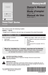
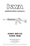
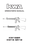
This is a translation of the original German operating instructions Operation of the T80 stair lift Contents Page 1 1.1 1.2 1.3 General................................................................................................................. Technical data ....................................................................................................... Ambient conditions............................................................................................... Test obligations...................................................................................................... 3 5 5 5 2. 2.1 2.2 2.3 2.4 2.5 Intended purpose of use....................................................................................... Transport profiles.................................................................................................. Inappropriate use ................................................................................................... Operator qualification ........................................................................................... Product description................................................................................................ General sketch of the platform lift ........................................................................ 5 5 6 6 6 7 3 Safety.................................................................................................................... 9 4 4.1 4.2 4.3 4.4 4.5 4.5.1 4.5.2 4.6 4.7 4.7.1 4.7.2 4.7.3 Operation ............................................................................................................. 11 Main switch .......................................................................................................... 11 Deep discharge protector and charging.................................................................. 11 Overload protector................................................................................................. 11 Battery charger ...................................................................................................... 11 Fetching and sending the platform lift................................................................... 12 Automatic platform................................................................................................ 13 Manual platform .................................................................................................... 13 Travelling with the platform lift.............................................................................. 14 What to do in the event of an unexpected standstill .............................................. 15 Hand wheel operation (metal hood)....................................................................... 15 Evacuation ……………......................................................................................... 16 Hand wheel operation (plastic hood)..................................................................... 17 Blank page............................................................................................................. 18 5 5.1 5.2 5.3 5.4 5.5 Options/extras ...................................................................................................... 19 Folding seat ............................................................................................................ 19 Emergency call....................................................................................................... 19 Lateral drive-on ramp............................................................................................. 19 Acoustic/visual signal............................................................................................ 19 Handheld transmitter.............................................................................................. 19 6 In the event of a malfunction............................................................................... 20 7 Acoustic warning signals ..................................................................................... 20 8 Services performed on your platform lift at a glance ....................................... 21 ! Important ! Please read the operating instructions before using the lift. Also make sure that everyone who uses the lift has read and understood the operating instructions. No rights can be derived from these operating instructions. Operating instructions T80PL 2014 1/21 (04/2014) EU declaration of conformity for machines (EU machinery directive 2006/42/EU) The manufacturer Lippe Lift- und Anlagenbau GmbH Weststrasse 48, 32657 Lemgo, hereby declares that the following machine Inclined stair lift / platform lift / type T80 conforms to the stipulations of the directive named above conforms to the stipulations of the following additional directives: EMC directive 2004/108/EU Low-voltage directive 2006/95/EU The following harmonised standards were applied respectively their protection target fulfilled: EN 81-40 (2009) EN 349 (2008) EN ISO 12100-1 (2004) EN ISO 12100-2 (2004) EN ISO 13850 (2007) EN ISO 13857 (2008) EN ISO 14121-1 (2008) EN 60204-1 (2007) The following notified body: TÜV AUSTRIA SERVICES GMBH (IDF no.: 0408) was employed for: EU type testing, test report no..: TÜV-A/MHF/MG MG09-06961 Responsible for the documentation: Lippe Lift- und Anlagenbau GmbH (Documentation Dept.) Weststrasse 48, D-32657 Lemgo Lemgo, 29/12/2009 _______________________ F.-W. Mueller (Managing Director) Operating instructions T80PL 2014 2/21 (04/2014) 1. General The rating plate provides the most important information about the platform lift. Type of machine Type description Year of manufacture Serial number Loading capacity of the platform Dead weight of the platform Manufacturer Field for details of the importer/dealer Operating instructions T80PL 2014 3/21 (04/2014) The T80 platform lift is equipped with many sensitive surfaces. Here is an overview: 1 = integrated in the safety circuit (further travel is not possible if activated) 2 = direction-related power-off (the lift can travel in the opposite direction) 3 = optional, in the safety circuit (further travel is not possible if activated) If a direction-related sensitive surface (Pos.2 / green) is activated, the lift stops and an acoustic signal will be activated. After two seconds the platform drives, without any command, for the length of 1,5 seconds in the other direction and stops then. Only now the acoustic signal stops. The “release-travel” can only be stopped by activating another sensitive surface, activating a safety switch or with the emergency stop. The first driving command after the “release-travel” has to be in the opposite direction as the last command. Operating instructions T80PL 2014 4/21 (04/2014) 1.1 Technical data: Permissible loading capacity: Continuous sound pressure level: Vibrations: Speed: Platform voltage: Battery charger voltage: max. 300 kg < 70 dB (A) < 0.5 m/s² (measurement inaccuracy ± 3%) approx. 0.1 m/s 24 V DC 230 V AC (55W) 1.2 Ambient conditions: Temperature range: Rel. humidity: -20 °C to +60 °C max. 100% 1.3 Testing obligations Whether or not the T80 platform lift is subject to an obligatory test depends on the respective national regulations and is the user’s responsibility. These regulations must be checked and adhered to. In Germany, a test is obligatory for systems with a lifting height of ≥ 3m. In each case, proof must be provided and documented in accordance with EN81-40 before the first use. The T80 platform lift is to undergo maintenance in accordance with the maintenance instructions at least once per year. We recommend that you take out a service contract with your dealer. 2. Intended purpose of use The T80 platform lift is intended for the transport of wheelchair users and/or people with reduced mobility. The platform travels between fixed access points along a permanently installed rail, which can be implemented straight or curved. The platform is guided over the stairs or an accessible inclined surface by the running rail. The system may only be operated by persons who have read and understand this user manual. 2.1 The following transport profiles are foreseen: 1. Transport of one person sitting in a wheelchair 2. Transport of one person sitting on the folding seat. 3. Transport of one person standing on the platform, provided that there is sufficient headroom and that the person has sufficient standing stability and can hold the hand grips securely (a separate set of documents is required, available on enquiry). 4. Transport of an additional person, provided that there is sufficient room on the platform and that the permissible loading capacity is not exceeded. Point 1 or point 2 is to be observed regarding this. Operating instructions T80PL 2014 5/21 (04/2014) A usage profile of 10 start-ups per hour is foreseen (with distances covered of max. 15 m for each start-up). In the case of longer distances covered, the number of start-ups should be reduced accordingly (and linearly). The T80 platform lift may be only operated if danger due to falling objects (such as flower pots) is ruled out. 2.2 Inappropriate use must be excluded, e.g.: Exclusive use for loads (if, in rare cases, loads such as shopping or beverage crates are transported, it is essential to ensure that the load is sufficiently stable and that the permissible loading capacity is not exceeded). Loads that protrude beyond the surface area of the opened base may in general not be transported (e.g. large pieces of furniture). The T80 platform lift is not a toy (children). Operation in potentially explosive atmospheres 2.3 Operator qualification: The operator of the platform lift must have unrestricted mental abilities. Operators with seriously impaired vision may be transported only with an attendant, whereby the attendant issues the driving commands. Furthermore, the operator must have read and understand the operating instructions. 2.4 Product description Our products combine the requirements for overcoming stairs with outstanding integration in the familiar environment in an appropriate way. On the one hand, the upper track tube can be used as hand rail and, on the other, the platform and track are painted according to your wishes in a colour from the extensive RAL pallet. The track does not need to be lubricated, as a result of which undesirable dirtying is ruled out. The permissible loading capacity is normally 300 kg (the measuring point for this is the centre of the base of the platform). The continuous sound pressure level is below 70 dB (A). We recommend that you take out a service contract. This guarantees the technically optimum condition of your T80 stair lift by means of regular maintenance. The maintenance interval is at least once per year. Operating instructions T80PL 2014 6/21 (04/2014) Platform lift with metal hood/front cladding 5 3 1 7 8 L2 2 L1 6 4 9 10 11 12 13 14 Item. 1 2 3 4 5 6 7 8 9 10 11 12 13 14 15 L1 L2 15 Designation Control unit Key switch Emergency stop button Plug seal Platform hood Main switch (situated inside) Hand grip Emergency call Left safety barrier Folding seat (option) Cover for motor/controller Right drive-on ramp Contact base Safety plate Lateral drive-on ramp (alternative to item 14) Main switch ON lamp Overload lamp Operating instructions T80PL 2014 7/21 (04/2014) Plattform lift with plastic hood/front cladding 5 4 2 7 8 3 1 6 9 11 16 10 12 13 14 Item 1 2 3 4 5 6 7 8 9 10 11 12 13 14 15 16 15 Designation Control unit Key switch Emergency stop button Control unit on spiral cable (option) Platform hood Main switch (situated inside) Holding bar Emergency call Left safety barrier Folding seat (optional extra, also with safety belt) Cover for motor/controller Right drive-on ramp Contact base Safety plate Lateral drive-on ramp (alternative to item 14) Plug seal Operating instructions T80PL 2014 8/21 (04/2014) 3. Safety and special instructions ATTENTION! Although your lift complies with the latest safety regulations, it is essential to follow the safety instructions below: Put the lift into operation only after reading the operating instructions and adhere to the operating instructions. Never exceed the permissible loading capacity. (Residual danger: breakage/failure of the brakes) Operate the lift only when seated (exceptions: see transport profile). Do not use the lift in the case of fire. Do not allow loosely hanging articles of clothing to get near to the running rail and the platform when the lift is moving. (Residual danger: trapping of loose clothing, etc.) Fold up the lift when not in use. (Residual danger: tripping over) Never place your hands near the running rail when the lift is moving. (Residual danger: crushing) Be sure to observe the track in the direction of travel when travelling. (Residual danger: crushing) Do not remove, cut through or deform parts of the lift or cladding; do not actuate operating elements with undue force. Do not push the barriers with undue force, neither while travelling nor when raising or lowering them. (Residual danger: falling from the platform) Stop the drive command immediately if there are obstacles or articles in or on the track or platform or in the driving area. (Residual danger: crushing) Do not remove any labels or signs belonging to the lift. Operating instructions T80PL 2014 9/21 (04/2014) Have repairs carried out exclusively by specialists. Do not allow any parts of the body or wheelchair to protrude beyond the base of the platform. Do not make any unnecessary movements on the platform, such as rocking or swinging. (Residual danger: falling from the platform) In the case of interior and exterior installations, brief or permanent flooding of the lift is forbidden. Remove dirt from the lift with a little polish or a damp cloth, not with a water jet. The load-bearing equipment and track must be sufficiently well lit by daylight or electric lighting. The electric lighting must be independent of timer circuits. Minimum 50 lux at the entry and exit points or in accordance with the national employee protection regulations. Operating instructions T80PL 2014 10/21 (04/2014) 4.1 Main switch The main switch (red key) is located inside the platform, behind the cover (p.7, 8/item 11). The key can be removed by turning it anti-clockwise, thus interrupting the electricity supply. (See 4.7.1 or 4.7.3 regarding the opening of the cover). The main switch must be actuated by technical personnel. 4.2 Deep discharge protector and charging The T80 platform lifts are equipped with automatic battery chargers. Charging takes place automatically when the platform lift drives into a loading station. The batteries do not require any care. All T80 platform lifts are equipped with an acoustic deep discharge protector. This acoustic signal generator is intended to protect the batteries against deep discharge. If the battery voltage drops below 22 V, a beep sounds at intervals of approx. 5 seconds. In this case you should drive immediately to the next charging station – if possible the lower charging station – and allow the lift to charge up there for several hours (this takes place automatically in the charging station). The beep stops after proper charging. The sound can be turned off by pressing the emergency stop button; this has no influence on the charging process. 4.3 Overload protector The T80 platform lift is equipped with an overload protector (acoustic and visual). In the case of the metal hood, the orange light on the hood (p.7/item L2) lights disappears; in the case of the plastic hood the background lighting of the direction arrows goes out (p.8/item 1). In addition, the internal beeper emits a continuous tone in the case of overload. This is based on the entire load being in the centre of the base of the platform. Reduce the weight if the overload protector is triggered. It may be sufficient just to shift the weight towards the running rail. 4.4 Battery charger (indicator lamps) The indicator lamps on the battery charger indicate the respective condition of the battery charger. A distinction must thereby be made between two different versions of battery charger. The main distinguishing feature is the number of LEDs. Green 3 LEDs: No electricity supply to the Off charger No battery connected On Charging On Battery fully charged On Yellow Off Red Off Flashes (briefly) Off Flashes slowly Off On, goes off briefly every 2 Off seconds. LED 1 LED: No electricity supply to the Off charger No battery connected Red Charging Yellow Battery fully charged Green Note: An acoustic signal sounds if the lift, outside a station, is not charged 30 seconds after the last motor movement. Operating instructions T80PL 2014 11/21 (04/2014) 4.5 Fetching and sending the platform lift (standard version) Ensure before each trip that the acoustic and, if present, the visual (optional) warning signals work. The T80 platform lift can be fetched from or sent to another station from any station. To do this, the key switch must be inserted at the respective station, turned in the appropriate direction and held in this position. The platform lift does not react immediately, but after a delay time of approx. 2 seconds. Note: The platform lift drives from the external control point only in the folded up condition, i.e. the base of the platform must be folded up and the safety barriers lowered to the bottom. Attention: In the case of a storey circuit (more than two stations) the platform lift is to be fetched or sent as follows: If the T80 platform lift has arrived at one of the middle stations, it stops there and opens or can be opened respectively. If the platform lift in not supposed to stop (open) there, the drive control on the external control unit must be briefly released and then pressed again immediately so that the platform continues to drive. Note: an LED is mounted on the radio transmitter for fetching/sending the platform lift. GREEN: batteries are OK ORANGE: the battery power is diminishing; renew the batteries at your earliest convenience RED: the battery power is very low; replace the batteries immediately Fetching and sending the platform lift (special version 1) [via the external control unit, only with 3-position key switch (p.7, 8/item 2) for a trip with the platform open via the external control unit]. This option must be activated by a specialist inside the controller. It must be ensured that no third person can suddenly get/jump into the path of the lift. Condition: driving area is 100% in view !!!! The key switch (p.7, 8/item 2) is to be set to position -II-, otherwise as in 4.5. Fetching and sending the platform lift (special version 2) [via the internal controller, only with 3-position key switch (p.7, 8/item 2)]. This option must be activated by a specialist inside the controller. The platform can be driven via the internal controller in the folded up condition. The key switch (p.7, 8/item 2) is to be set to position -II- in order to do this. The platform lift can now be driven via the internal controller (p.7, 8/item 1). If there are more than two stations: The platform lift will stop automatically at each intermediate station and will open if an automatic platform is fitted. If this is not desired, a new drive command must be given and the platform lift continues to drive. Operating instructions T80PL 2014 12/21 (04/2014) 4.5.1 Automatic platform In the case of the automatic platform the base folds up and down electrically and the safety barriers raise and lower electrically. This is performed by means of an UP or DOWN command issued from a station (see also paragraph 4.5), or via the internal controller in the case of special version 2. The control button must be pressed and held (so-called jogging mode) until the folding procedure is complete. If a malfunction should occur during the folding procedure, then the platform is to be folded up or opened manually (see paragraph 4.5.2) and customer service informed. 4.5.2 Manual platform The folding procedure at a step can/may only be carried out by an attendant. In order to fold up the platform by hand, proceed as follows (as shown below): a) Place the safety barriers in the horizontal position. b) Fold up the base of the platform. c) Lower the safety barriers so that they rest against the base of the platform. The respective barrier on the downhill side is implemented correspondingly longer in order to enable safe operation. Proceed in the reverse order to open the platform again and finally raise the safety barrier at the desired access point right up to the top (vertical). Operating instructions T80PL 2014 13/21 (04/2014) 4.6 Travelling with the platform lift (standard version) Ensure before each trip that the acoustic and, if present, the visual (optional) warning signals work. The following control elements are located on the platform: a) Key switch Function -I- and -0(p.7,8/item 2) b) Control unit Function UP and DOWN (p.7, 8/item 1) c) Pushbutton EMERGENCY STOP (red button) (p.7,8/item 3) After driving or stepping onto the platform, insert the key and turn it to position -I-: ! In the case of the automatic platform, the safety barrier closes electrically when the pivot lever or button is pressed and held in the desired direction of travel. The platform lift begins to move once the barrier has closed. ! In the case of the manual platform, first close the safety barrier by hand (horizontal position), then press and hold the pivot lever or button in the desired direction of travel. Upon reaching the destination station: ! The platform lift stops automatically (the respective position is set during the installation). ! In the case of the automatic platform, press and hold the pivot lever or button until the safety barrier has opened. ! In the case of the manual platform, release the pivot lever or button and open the safety barrier by hand. In the case of a storey circuit (more than two stations), drive as follows with the T80 platform lift: ! If the platform lift has reached one of the middle stations, it stops there and, in the case of the automatic platform, raises the safety barriers. If the platform lift in not supposed to stop (open) there, then briefly release the control element and press it again immediately so that the platform lift continues to drive. Travelling with the platform lift (special version 1) [via the external control unit, with 3-position key switch (p.7, 8/item 2) for a trip with the platform open via the external control unit]. This option must be activated by a specialist inside the controller. It must be ensured that no third person can suddenly get/jump into the path of the lift. Condition: driving area is 100% in view !!!! The key switch (p.7, 8/item 2) is to be placed in position -II-, otherwise the procedure is the same as described under ‘standard version’, with the difference that only the external control unit is used here. Travelling with the platform lift (special version 2) The key switch (p.7, 8/item 2) is to be placed in position -I-, otherwise the procedure is the same as described under ‘standard version’. Operating instructions T80PL 2014 14/21 (04/2014) 4.7 What to do in the event of an unexpected standstill, e.g. due to a power failure? We recommend that a working mobile telephone be carried in order to alert the rescue services. 4.7.1 Hand wheel operation / by technical personnel only (version with metal hood) The T80 platform lift can also be operated manually. Manual operation must be performed by technical personnel! The procedure is as follows: a) Press the EMERGENCY STOP button (p.7/item 3) on the platform. b) Loosen the screws of the hood. Tool for is supplied in the envelope. c) The platform hood (p.7/item 5) is to be raised and secured against falling down by means of the vertically adjustable lever. d) The brake venting lever (loop) must be pulled upwards and the hand wheel on the end of the motor shaft must be turned simultaneously. In doing so, the direction of travel should always be towards the lower station (less energy expenditure when turning the hand wheel). The respective direction of rotation is indicated directly on the hand wheel. Note: If the cause of the standstill is not clear, it should be assumed that the safety arrester has been triggered and that its safety switch has led to the lift switching off. The safety arrester may only be reset by technical personnel. In this case, proceeded as described above, but first turn the hand wheel in the UP direction (until the lift has moved approx. 5cm along the running rail), after which the hand wheel can be turned in the DOWN direction. Brake venting lever Hand wheel Operating instructions T80PL 2014 15/21 (04/2014) 4.7.2 Evacuation / only by technical personnel Proceed as follows in order to help the operator out of the lift: Press the EMERGENCY STOP button (p.7, item 3) on the platform. Remove the plug seal (for the emergency unlocking) on the front cladding on the uphill side using a screwdriver or similar. Press the lever shown in the picture (below right) downwards using a suitable tool. The operator can now be helped out at the uphill side. The platform must be folded up by hand so that the lift does not block the staircase (see 4.5.2). Operating instructions T80PL 2014 16/21 (04/2014) 4.7.3 Hand wheel operation / by technical personnel only (version with plastic hood) The T80 platform lift can also be operated manually. Manual operation must be performed by technical personnel! The procedure is as follows: a) Press the EMERGENCY STOP button (p.8/item 3) on the platform. b) Remove the screws from the hood, pull off the cables and remove the hood in an upward direction. d) The brake venting lever (loop) must be pulled upwards and the hand wheel on the end of the motor shaft must be turned simultaneously. In doing so, the direction of travel should always be towards the lower station (less energy expenditure when turning the hand wheel). The respective direction of rotation is indicated directly on the hand wheel. Note: If the cause of the standstill is not clear, it should be assumed that the safety arrester has been triggered. The safety arrester may only be reset by technical personnel. In this case, proceeded as described above, but first turn the hand wheel in the UP direction (until the lift has moved approx. 5cm along the rail), after which the hand wheel can be turned in the DOWN direction. Brake venting lever Operating instructions T80PL 2014 Hand wheel 17/21 (04/2014) Blank page Operating instructions T80PL 2014 18/21 (04/2014) 5 Options/extras Depending upon requirements, the T80 platform lifts are also equipped with the following extras. 5.1 Folding seat All of our platform lifts can be equipped or retrofitted with a folding seat if desired (p.7, 8/item 10). The folding seat is intended as a seat for nonwheelchair users who wish to use the platform lift. When folded up, the seat lies against the platform wall to save space. The folding seat is equipped with a seat belt, which must be fastened while travelling if the user is not able to hold on to the barrier or the hand grip with a hand. 5.2 Emergency call All platform lifts must be equipped with an emergency call system. There are further versions in addition to the standard version: - A gong, which is activated wirelessly. The transmitter, which is powered by a separate battery, is located on the platform hood and relays the emergency call signal to the gong (wireless). The range lies between 40 m (in non-built-up areas) and at least 10 m (in builtup areas). - The best method of making an emergency call is, however, still with a mobile telephone. 5.3 Lateral drive-on ramp In some cases (staircases) it is not possible to drive onto the platform over the two standard drive-on ramps due to the space in front of the first step. In these cases an additional drive-on ramp is to be mounted on the long side of the platform (p.7, 8/item 15). 5.4 Visual warning signal A visual signal (flashing orange light on the hood) is activated each time the stair lift motor moves. This increases safety in publicly accessible areas. The repetition frequency of the signal is approx. 1 second. 5.5 Handheld transmitter If you’ve ordered a handheld transmitter, an additional manual will be attached to this manual Operating instructions T80PL 2014 19/21 (04/2014) In the event of a malfunction 6. Malfunction Lift does not function at all Possible cause Remedial action Is the key on the control unit at -I- and are the others at -0- or removed? Are all EMERGENCY STOP buttons unlocked? Set the key switches correctly (see 4.5 or 4.6) Unlock the EMERGENCY STOP buttons by turning or pulling (depending on version) Turn on the main switch (see 4.1) Inform technical personnel Is the main switch for the lift at -I- ? Safety arrester has triggered Lift does not start when the platform is open and occupied Are the safety barriers in the horizontal position? Automatic only: Lift does not fold automatically Are all key switches set to -0- except at the operating station chosen by you? In the case of wireless operating stations: are the transmitter batteries OK? Are the drive-on ramps and the safety plate (if fitted) freely movable? Actuate the safety barriers again, if necessary move them slightly upwards or downwards Push the drive-on ramps and safety plate slightly to the outside. Drive in the opposite direction. Set the key switches correctly (see 4.5 or 4.6) Replace the transmitter batteries If you cannot repair the error yourself in this way, please inform your customer service. 7. Acoustic warning signals Duration [sec] 0.1 0.1 0.1 2x short Reason Pause [sec] 5.0 Low battery voltage (see also 4.4) 0.5 Acoustic drive warning 0.25 “release travel” (see. page 4) 4.0 Overtemperature of motor/electronics, or defective fuse 3x short 4.0 Continuous ---tone Faulty electronics/motor Emergency call by means of beeper on the platform, or overloading Remedial action Drive to the charging station and charge the batteries --------It is possible to resume driving after a cooling down period of approx. 5 min. (If cooling is insufficient, the cooling period is extended by a further 5 min.) Inform customer service Release the emergency call button. Shift centre of gravity towards the rail or reduce the weight Note: The acoustic warning signal can be suppressed by pressing the emergency stop button; the charging procedure is retained. Operating instructions T80PL 2014 20/21 (04/2014) 8. Services performed on your T80 platform lift at a glance Installed on: Serial no.: Installed by: TÜV acceptance on: No. Date Service performed Signature 1 2 3 4 5 6 7 8 9 10 11 12 13 14 15 16 17 18 19 20 21 22 23 24 Operating instructions T80PL 2014 21/21 (04/2014)