1
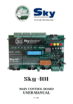
SKY ELEVATOR CX Series Lift Control System USER MANUAL Sayfa 1 / 36 CX SERIES LIFT CONTROL SYSTEM USER MANUAL VERSION : 1.4 SKY ELEVATOR SKY ELEVATOR SKY ELEVATOR www.sky-elevator.com İkitelli Osb Metal İş San. Sit. 19. Blok No:1 /İSTANBUL - EUROPE Tel: +90 444 1988 Sayfa 2 / 36 CONTENTS CONTENTS………………………………………………………………………………... PREFACE………………………………………………………………………………….. GENERAL DESCRIPTION……………………………………………………………….. A) CONFIGURATIONS AND COMPONENTS…………………………………… B) PANEL VOLTAGE INFORMATION…………………………………………... C) INPUTS AND OUTPUTS……….………………………………………………. OUTPUT TERMINALS AND THE MEANINGS OF THE ABBREVATIONS…………. PROGRAMMING CX SERIES….………………………………………………………... A) SETTING PARAMETERS………………………………………………………. B) PARAMETER LIST……………………………………………………………... CX SERIES ERROR CODES……………………………………………………………... CX HAND TERMINAL……….….……………………………………………………….. A) LCD SCREEN AND KEYPAD USAGE……...…...….…………………………………………… B) MONITORING OF INPUTS...……...……………………………………………………………… C) MAIN MENU.……………………………………………………………………………………… D) SETTING PARAMETERS………………………………………………………………………… E) ERROR LOG AND ERROR CODES…..………………………………………………………….. F) LANGUAGE……………………………………………………………………………………….. G) PARAMETER TRANSFER………………………………………………………………………... Sayfa 3 / 36 PAGE 3 4 5 5 5 5 6 7 7 9 18 19 19 21 22 22 24 25 25 PREFACE CX Series Lift Control System has been designed to fulfil the needs of lift sector at new age. One of the main aims of this series is to integrate lift control system with today's advanced computer systems. CX Series Lift Control System is controlled by a 16-bit high performance microcontroller. It works in one speed, two speed and VVVF systems. In this manual you find information about using CX Series Lift Control System and technical documents and schematics. If you think that this manual is not enough or it is not compatible with hardware or software version of your system, you can download latest version of the manual from Sky Elevator's website (www.sky-elevator.com) or send an e-mail to request by mail. We will continue to develop this product with your support and suggestions. Therefore if you face any problem while using this product or if you have any suggestions to make it better, please inform us by e-mail ([email protected]). Sky Elevator Sayfa 4 / 36 GENERAL DESCRIPTION A) CX SERIES BOARDS AND THEIR FUNCTIONS a) CXA Main Board This board is the main board of the system. It contains microcontroller, main inputs and outputs, 16 I/O for call registers, 7-Segment display, keypads and signal lamp drivers. b) RLE This board contains 2 programmable inputs and 4 programmable output relays. It is an optional board and only used when extra input or output is required. c) SWPI It is the I/O board for the call registers. One board contains 16 I/Os. Each channel is input for buttons and output for call register lamps. The number of SWPI required in a system depends on the total number of buttons required. This board is connected to the main board via the parallel bus. d) SWPOR SWPOR board contains 8 relays for output. It is possible to use more than one SWPOR board which can be programmed up to two different purposes at the same time. This board is also connected to the main board via the parallel bus. e) CXK It contains terminals of panel. Input signals from shaft and display outputs are connected via this board. f) HTT Hand terminal with LCD for parameter monitoring and setting. B) PANEL VOLTAGE INFORMATION a. Safety Circuit Voltage: Depends on the contactor coil voltage. Maximum allowed voltage is 230V AC. Minimum 100 VA power supply is required. b. Signal Voltage: 24V DC is used for signal lamps and control of relays on the boards. The current of this supply is mainly determined by the current requirements of the pushbuttons used in the system. Minimum 100 VA power supply is required. c. Microcomputer Voltage: 10V AC is required for the power supply of the microcomputer circuit. Maximum 1A capacity is enough. Minimum 25 VA power supply is required. C) INPUTS AND OUTPUTS The power supply for signal and control is 24V DC. All inputs except safety circuit monitoring are active low. It means that an input signal is active if it is connected to the return (0V) of 24V circuit. All inputs are 100% galvanically isolated from the microcomputer circuit. The outputs are mainly made of relays. Some inputs/outputs are dedicated to a special purpose and some of them are user programmable. Sayfa 5 / 36 OUTPUT TERMINALS AND THE MEANINGS OF THE ABBREVIATIONS 100 1000 10AC L1-R, L2-S,L3-T MP / N 110 120 130 135 140 150-151 18AC 840 804 805 802 FKK M0 MK Signal Circuit Supply (+24V DC) Signal Circuit Ground 10V AC Voltage DTS K20 DCM Open Door Button Close Door Button Door Signal Common Main Phases CLS Close Door Signal (Automatic Door) Open OPN A,B,… …,G 2BC(1),2G(-) K1, K2 Neutral Safety Circuit Supply Stop Circuit Return Door Contacts Return Automatic Cabin Door Contact Return Door Locks Return Safety Circuit Common 18V AC Voltage Positive Terminal of Brake Overload Input Full Load Input Half Load Input Phase Failure Detector Input Counter Floor Detector KF RU RD RH RF 500 501 869 RUN DER CNT 2000 Negative Terminal of Brake D1,D2,D3 2001 Positive Terminal of CAM VK 810 Negative Terminal of CAM R-N 817 Lower Limit (End of Fast Speed Way) 1 818 Upper Limit (End of Fast Speed Way) 2 SXX SFP SK SKL AL KL S1 O1,O2,O3 U1,V1,W1 U2,V2,W2 FKK/AFK FAN Fuses Brake and Cam Fuse Contactor Fuse (220V AC) Cabin Lamp Fuse Safety Line and Contactor Supply Fuse Motor High Speed Inputs Motor Low Speed Inputs Phase Failure Detector Board Supply Voltage for Motor Fan T1-T2 PTC Motor Thermistor Terminals C0,C1...C16 TMS TR Thermal Magnetic Circuit Breaker Thermal Relay Hall Call Common For Simple Push Button Programmable Inputs Common of Register Lamps SWCX 190 I0,I1,I2 COM Door Signal (Automatic Door) Right Display Segment Outputs Left Display Segment Outputs VVVF System Motor Output Contactors VVVF System Break Contactor Up Direction Contactor Down Direction Contactor High Speed Contactor Low Speed Contactor Inspection Down Motion Button Inspection Up Motion Button Inspection Input Signal Frequency Input in VVVF Device Error in VVVF Contactor Control Input Break, Pump and Signal Circuit Bridge Diodes Contactor Supply Voltage Input Phase-Neutral Line Input (Before Phase Protection Relay and Main Switches) Phase Line Output For Cabin (220V AC) Phase Line Output For Cabin Lamp (220V AC) Automatic Door Open Limit Automatic Door Close Limit Programmable Output Relay Programmable Output Relay on RLE 12 Busy Signal 31 32 35 39 VTM FIRE Down Arrow Signal Up Arrow Signal Overload Signal Out Of Service (Inspection) Signal Registration Button Inputs/Register Lamp Outputs Watman Input Fire Input FOT Photocell Input 870 Electrical Emergency Operation Switch Sayfa 6 / 36 PROGRAMMING CX SERIES System parameters of CX Series lift controllers can be observed and modified easily by using three buttons located on the electronic board. These buttons are named as follows: ↓ ENT ↑ A) MODIFYING PARAMETERS You have to hold your finger pressed onto the (ENT) button until you see the following display on the board displays (ENT)............(ENT) PAd Here you see P flashing. Press (ENT) button once to enter programming the parameters. You will see the following screen: n00 Now the system is in programming mode. You can analyse all parameters. This display structure (letter 'n' in first display) shows the program number ('00' in this example, left two displays). The programs with the numbers 00…15 are used for hall and cabin display patterns. Other programs are used as system parameters in controller. In order to see or modify the data stored in a program number, first you have to find it. When you entered the programming mode first you see a display exactly as above. You can increase program number by pressing (↑) button or decrease it by pressing (↓) button shortly. But when you have reached lower and upper limits then the program number cycles to the opposite limit. For example let us assume the display shows program 21 as follows: n23 (↓ ) n22 (↓ ) n21 In order to see the data stored in a program cell you have to press (ENT) button shortly. n21 (ENT) Sayfa 7 / 36 008 Now the display shows the data stored in program number 21. As an information program number 21 stores the number of stops (floors) in the system. So this controller works with 8 stops. In order to increase or decrease the data (the number of stops in the system) first get it to inspection mode and then use (↑) and button (↓) exactly as in program finding procedure (↓ ) 007 (↓ ) 006 After setting the data (found the number in display which corresponds to the number of stops in the controller) press (ENT) button once to return to the previous level (program selection level). (ENT) n21 You can observe and/or modify as many programs as you want in one programming session. Be aware that modified data until now is not written to the EEPROM (permanent memory). The modified data is still in RAM (temporary memory). But when you exit from program selection level by pressing (ENT) button long enough then system leaves the programming mode and last configuration is stored into EEPROM and the controller uses these new parameters in operation. After this point any power breakdown does not influence the parameter memory. When you exit from programming mode by holding (ENT) button down until the display shows the current floor of car, then system is ready to function as a controller again. (ENT)..............(ENT) 3 Where 3 stands for floor number Sayfa 8 / 36 B) PARAMETER LIST n0… …15 n20 n21 n22 n23 n24 n25 n26 n27 n28 n29 n30 n31 n32 n33 n34 n35 n36 n37 n38 n39 n40 n41 n42 n43 n44 n45 n46 n47 n48 n49 n50 n51 n52 n53 n54 n55 n56 n57 n58 n59 n60 n61 n62 n63 n64 n65 n66 n67 n68 n69 n70 Digital display codes for floors 0…15 Programming codes Number of stops Lift traffic system Lift door type Definition of parking floor Parking floor Maximum door lock waiting time Selection for automatic door open/closed wait state at floor (Only in full automatic door) Busy time Automatic door open waiting time Waiting time in floor before departure for the next floor (only in collective models) FIRE stop Maximum floor transition period (High Speed) Maximum busy period Definition of error reporting Display output type Software version MK Delay Start up delay Slow speed travel period Door open period Park time System blocking after errors Number of doors in car Door A definition (0-7 floors) Door A definition (8-15 floors) K20 Delay Lift type Maximum number of errors Period to inhibit door close button Delay to operate door close command Programmable output (S1-On CXA board) Programmable output (O1-On RLE board) Programmable output (O2-On RLE board) Programmable output (O3/O4-On RLE board) Programmable input (I0-On CXK board) Programmable input (I1-On RLE board) Programmable input (I2-On RLE board) Door B definition (0-7 floors) Door B definition (8-15 floor) Maximum motor period Direction delay Open door delay Motor motion control period Brake delay Hall call cancelling Inspection switch selection Inspection speed selection Stop failure Relay board 1 (SWPOR definition) Relay board 2 (SWPOR definition) Sayfa 9 / 36 PROGRAM 0… …15 : These programs store the digital display codes for the corresponding floors. Program 0 holds the code for the floor 0 and program 6 the code for the floor 6. These codes control hall and cabin displays but not the display on mainboard. When you enter program 0…15 then you will see the characters to be displayed on the panels when the lift stays at that floor. Search with (↓) and (↑) keys all characters, which are possible to be displayed for the system. PROGRAM 20 : This program does not store any data for any controller function. Program 20 is used to shortcut for some popular digital display configurations. Here are allowed commands for program 20 and their functions: 1 2 3 8 11 21 22 23 39 57 This command shift all programs between 0…15 one step up. After executing this command program 0 is shifted to 1, program 1 is shifted to 2 and so on. For example a system like 0,1,2,3,4,… is 0,0,1,2,3,… after execution. This command shift all programs between 0…15 two step up. After executing this command program 0 is shifted to 2, program 1 is shifted to 3 and so on. For example a system like 0,1,2,3,4,… is 0,1,0,1,2,3,… after execution. This command shift all programs between 0…15 three step up. After executing this command program 0 is shifted to 3, program 1 is shifted to 4 and so on. For example a system like 0,1,2,3,4,… is 0,1,2,0,1,2,3,… after execution. This command shift all programs between 0…15 one step down. After executing this command program 1 is shifted to 0, program 2 is shifted to 1 and so on. For example a system like 0,1,2,3,4,… is 1,2,3,4,5,… after execution. This command fills the program memories 0 to 15 with the digital codes for numbers 0…15. So resulting digital codes are 0,0,1,2,3,4,5,… This command organises digital display numbers as -1,0,1,2,3,… This command organises digital display numbers as -2,-1,0,1,2,… This command organises digital display numbers as -3,-2,-1,0,1,… Delete all error reports. Restore factory defaults. PROGRAM 21 : This program holds the number of stops in lift system. You can enter any number between 2 and 16. PROGRAM 22 : This program stores the parameter which decides the traffic system of the lift as follows: Simple Push Button Car and hall call buttons are connected together. There is no call register memory. No 0 second call is registered when the system deals with a call. No group operation is allowed. Hall calls are not allowed in busy state. Simple Collective Car and hall call buttons are connected together. Call register memory is present. There is 1 no difference between hall and car calls. One Button Down Collective Car and hall call buttons are connected separately. Car calls are collective in both 2 directions where hall calls are collective in downwards. This configuration is useful in residential buildings where the main entrance is in the base floor. One Button Up Collective Car and hall call buttons are connected separately. Car calls are collective in both 3 directions where hall calls are collective in upwards. Two Buttons Full Collective Car, hall up and hall down buttons all are connected separately. Car and landing call are 4 all serviced in full collective manner. Sayfa 10 / 36 PROGRAM 23 : This program stores the parameter for lift door as follows: 0 Semi-automatic wing landing door, no cabin door 1 Semi-automatic wing landing door, with automatic cabin door 2 Full automatic cabin and landing door PROGRAM 24 : This program defines the parking facility of the lift as follows: 0 No park floor is defined 1 System has a park floor where car waits with closed doors. 2 System has a park floor where car waits with open doors. If this parameter is 1 or 2 then the car moves to defined park floor (program 25) when no call is present during defined time period (program 41) after last travel. PROGRAM 25 : This program stores the parking floor if program 24 is 1 or 2. This number must be less than the number stored in program 21. PROGRAM 26 : This program stores maximum time period (3.0 - 20.0 sec) to wait door lock to be closed after a door close signal is sent. The data is displayed in seconds and can be adjusted in 0.1 second steps. PROGRAM 27 : The data stored in this program determines the behaviour of the door when the car is at floor level. 0 The car waits with closed doors in floor for automatic doors. 1 The car waits with open doors in floor. (Not conformity with EN81-1) PROGRAM 28 : This program stores busy period (3.0 - 10.0 sec). The data is displayed in seconds and can be adjusted in 0.1 second steps. PROGRAM 29 : This program stores the time period (4.0 - 15.0 sec) to wait doors to be open before reclosing them when the doors are full automatic. The data is displayed in seconds and can be adjusted in 0.1 second steps. PROGRAM 30 : This program is used only in collective systems. It stores the parameter for the time period (3.0 10.0 sec) where the car waits before departure for the next call. The data is displayed in seconds and can be adjusted in 0.1 second steps. PROGRAM 31 : This program stores the floor to where car goes in case of fire. After reaching fire-floor car waits there with open doors. PROGRAM 32 : This program stores a parameter which stands for the maximum time (5.0 - 99.9 sec) allowed the car to move from one floor to the next one. If this time is exceeded then the car is stopped by the system and an error is reported (249). The data is displayed in seconds and can be adjusted in 0.1 second steps. In case of any mechanical problem, which prevents the car from moving or any fault in floor detector occurs; system may cause some big problems if the motor is not switched off immediately. It is strongly recommended to adjust this function properly when the lift is in service. Sayfa 11 / 36 PROGRAM 33 : This program stands for maximum busy time (0.0 - 99.9 sec). If the door stays open for a long time then the cabin light and busy signal are switched off after the period stored in this program. The data is displayed in seconds and can be adjusted in 0.1 second steps. PROGRAM 34 : This program is used to control error reporting mechanism. The allowed numbers and their functions are as follows: 0 1 System reports all errors and stops the car . Only safety circuit errors are reported and the car is stopped only in safety errors. Secondary errors like 249, 250, 252, 253,… are not processed. PROGRAM 35 : This program is used to set display output to 7 segment digital display, gray code or binary code. 0 7 Segment Digital Display 1 Gray Code (M0/G-Segment, M1/F-Segment, M2/E-Segment, M3/D-Segment) 2 Binary Code (Bit0/G-Segment, Bit1/F-Segment, Bit2/E-Segment, Bit3/D-Segment) PROGRAM 36 : This program displays the software version number. PROGRAM 38 : This program stores a parameter which stands for a delay time (0.0 - 5.0 sec) during start-up. The data is displayed in seconds and can be adjusted in 0.1 second steps. The car waits for a time delay specified in this program after the door lock closed signal returns to the controller before activating contactors to start motion. PROGRAM 39 : This program stores a parameter which stands for the time limit (5.0 - 30.0 sec) in slow motion. The data is displayed in seconds and can be adjusted in 0.1 second steps. When the car moves in slow motion and the time elapsed exceeds the parameter specified in this program then the car is stopped. PROGRAM 40 : This program stores a parameter for door open time limit (0.0 - 10.0 sec). The data is displayed in seconds and can be adjusted in 0.1 second steps. When the door is activated to open and elapsed time exceeds the parameter specified in this program while the door is still closed then an error signal is generated and the door is deactivated. PROGRAM 41 : This program stores a parameter which stands for the time (0.0 - 99.9 sec) to wait to move to the park floor. The data is displayed in seconds and can be adjusted in 0.1 second steps. When the car stays without receiving a call from any floor for a time period specified in this program then a cabin call is given automatically by the system. PROGRAM 42 : This program stores a parameter which controls system lock after some errors. These parameters are as follows: 0 The system continuous operation. 1 The system is blocked if the number of consequent errors exceeds the number stored in the parameter n48. All call registers are cleared. 2 PROGRAM 43 : This program stores the number of doors present in the car as 1 or 2. PROGRAM 44 : This program stores the stops (0…7) at which the first door (Door A) in the car is active. In order to calculate the data for this program you have to add the numbers for the stop at which the first door is active. Sayfa 12 / 36 FLOOR 0 CODE 1 1 2 2 4 3 8 4 16 5 32 6 64 7 128 For example assume that we want the first door to be active at stop 0, 3, 4, 6 and passive at other stops. To calculate the data, sum the codes for each stop: Stop 0 Stop 3 Stop 4 Stop 6 : : : :+ 1 8 16 64 ------------89 If we enter 89 into to program 44 then the first door will be active only at Stop 0, 3, 4, and 6. PROGRAM 45 : This program stores the stops (8…15) at which the first door (Door A) in the car is active. In order to calculate the data for this program you have to add the numbers for the stops at which the first door is active. FLOOR CODE 8 1 9 2 10 4 11 8 12 16 13 32 14 64 15 128 For example assume that we want the first door to be active at stop 9,10,13,15 and passive at other stops. To calculate the data, sum the codes for each stop: Stop 9 : 2 Stop 10 : 4 Stop 13 : 32 Stop 15: + 128 --------------166 If we save 166 into to program 45 then the first door will be active only at stops 9, 10, 13 and 15. PROGRAM 46 :This parameter only Works in systems with automatic door. On signal in door open switch input (K20), it determines the time of door open signals. Time unit is second and can be set min 0,6 sec, max 8 sec. PROGRAM 47 : This program defines the lift type 1 One speed rope lift 2 Two speed rope lift 3 Not used 4 VVVF1 5 VVVF2 6 FUJI closed loop 7 RST 8 VVVF3 9 KEB 10 DIETZ Sayfa 13 / 36 PROGRAM 48 : This program stores the maximum error (minimum 4) becomes continually. System will blocked if errors exceed this value. PROGRAM 49 : This program controls the DTS (Close Door) button only in full automatic door systems. DTS (Door close button) is inhibited during the time period (0.0 - 10.0 sec.) given in this parameter. The period starts when the car reaches the floor. The data is displayed in seconds and can be adjusted in 0.1 second steps. PROGRAM 50 : This program defines time period (0.0 - 2.0 sec) to delay the activation of retiring cam after the landing door has been closed for semi-automatic systems. The data is displayed in seconds and can be adjusted in 0.1 second steps. PROGRAM (51… …54) : There are 4 programmable relays in CX Series boards. S1 is standard in all systems. But other programmable relays (O1, O2, O3/O4) in RLE board are optional. Here are the details of the programmable outputs: PROG. NO CODE PLACE CONTACT V/I 51 S1 RLX 220V/10A 52 53 O1 O2 RLE RLE 48V/3A 48V/3A 54 O3/O4 RLE 48V/3A CONTACT TYPE Normally Open Common Normally Open Normally Open DEFINITION Always programmable O1, O2 and O3/O4 relays are all have same common Normally Open terminal. O3/O4 works in parallel. Sayfa 14 / 36 OUTPUT CODE 1 2 3 4 5 6 7 8 9 10 11 13 14 15 16 17 18 19 20 24 25 26 27 30 31 32 33 39 40,41,42,43 45 46 47 51 53 54 55 200+i SELECTED CASE orFUNCTION Stop circuit is closed (Terminal 120 isoon) Stop circuit is open (Terminal 120 is off) System is in Inspection mode (Terminal 869 is on) System is in Normal mode (Terminal 869 is off) There is an error There is no error, system works normal The car is moving in Slow speed The car is not moving in Slow speed The car is not moving The car is moving in any speed The car is moving in Fast speed Door Lock circuit is closed (Terminal 140 is on) Door Lock circuit is open (Terminal 140 is off) The cabin is at floor level The car is staying in Rest and the cabin is at floor level Direction is up Direction is down Busy The system is moving or in START state Waiting for park period The system is in motion or in braking Retiring cam. Door contacts are closed and there is motion. In normal mode : The system is in motion or in braking In inspection mode : The system is in motion The system is in motion or door lock is on. This output is specially to drive the contactor in speed control systems. There is no call registered. ZERO SPEED output for VVVF drives. (JOG) The system is in inspection mode and in motion RESET output for a driver. This output is active as a pulse when a device error is detected (DER). Gray Code M0, M1, M2, M3 outputrespectively Door Close command input for the second door Door Open command input for thsecond door Gong Door Lock + Brake Down ServiceArrow Up Service Arrow Maximum StartCounter The car is staying in rest at itfloor Sayfa 15 / 36 PROGRAM 55… …57 : In CX lift control system only 16 inputs are constant. You cannot redefine or change the terminal of the following inputs 120, 130, 140, 870, 817, 818, 500, 501, 869, M0, MK, 804, K20, FKK, DTS and CNT. All other inputs must be programmed by the user according to the needs of the system. Any input can be selected from the available inputs in the list below and can be connected to the desired terminal. The following list gives the input codes and their explanations. PROGRAM NO 55 56 57 PARAMETER VALUE 1 2 3 4 5 6 7 8 9 CODE I0 I1 I2 INPUT CODE FIRE 805 802 WTM RUN FOT SIF SIS DER BOARD NAME CXK RLE RLE DEFINITION Fire Full Load Minimum Load Waitman VVVF Frequency Control Photocell Input Simulation Inputs (Slow/Fast) VVVF Device Error PROGRAM 58 : This program stores the stops (0…7) at which the second door (Door B) in the car is active. Set this parameter as program 44. PROGRAM 59: This program stores the stops (8…15) at which the second door (Door B) in the car is active. Set this parameter as program 45. PROGRAM 60 : Maximum time period (20.0 - 99.9 sec) in which motor is allowed to work continuously. (To set this parameter more than 450 (45 sec) is not conformity with EN81 standards. The data is displayed in seconds and can be adjusted in 0.1 second steps. PROGRAM 61 : Delay period (0.0 - 11.0 sec) to allow the direction to change after stopping. The data is displayed in seconds and can be adjusted in 0.1 second steps. PROGRAM 62 : This parameter stores the time period (0.0 - 3.5 sec) necessary for the automatic door to open after reaching the floor. The data is displayed in seconds and can be adjusted in 0.1 second steps. PROGRAM 63 : If there is no signal input to the programmable input with code 5 (RUN) within the time period specified in this parameter (0.0 - 10.0 sec) after a motion command is received then the system is stopped and report error 247. If RUN input is not defined then this timer is not active. The data is displayed in seconds and can be adjusted in 0.1 second steps. PROGRAM 64 : Brake delay (0.0 - 5.0 sec) in ACVV and VVVF systems. The data is displayed in seconds. You can adjust it in 0.1 seconds. This parameter defines the time delay for programmable relays for selection number 21-25-27. PROGRAM 65 : Use for hall calls setting. 0 Hall calls are allowed 1 Hall calls are inhibited Sayfa 16 / 36 PROGRAM 66 : This program defines the inspection input contact type. 0 Closed contact in inspection mode 1 Open contact in inspection mode PROGRAM 67 : This program defines the inspection speed. 0 Inspection speed is the slow speed in the system. When there is a motion command in inspection mode then only direction command is sent, neither slow nor high speed is activated. PROGRAM 68 : This program defines the call register cancelling or not in stop failure during motion. 2 0 System continues to work 1 All of the call registers are cleared and the system continues to work. PROGRAM 69-70: This program defines the functions of SWPOR boards added to the system. 0 Not used 1 Floor indicator lamps 2 Gray code output of car position 3 Binary code output of car position Sayfa 17 / 36 CX SERIES ERROR CODES CODE 12 0 130 135 EXPLANATION This code is reported when the stop circuit is broken during motion This code is reported when the door contact circuit is broken during motion. Door could not be opened. This shows that after giving Open Door command door contact circuit was not broken. 140 Door lock cannot be sensed as closed after cam or door close signal is applied. 141 This code is reported when door lock circuit Is broken during motion. 225 226 241 SUGGESTIONS Check landing door contact in semi-automatic door and cabin door contact in full automatic door. Door lock circuit may be shorted. Check n40 parameter. Check n26 parameter setting. It must be set right for door dimensions. And be sure that close door signal (DCM and CLS) is ready, retire cam is active and connection of 140 terminal is OK. This code is reported when the parking floor (program 25) is greater than maximum number of stops (program 21). This code is reported when the fire- floor (program 31) is greater than maximum number of stops (program 21). This code is reported when KSR1 and KSR2 are open at the same time. This error is also reported when stop circuit is open. 247 No motion detected in defined time. 249 This code is reported when no change in floor number is detected in the time interval defined in program 32 or 39, when the car is in motion. This error may be caused by any mechanical or electrical fault, which inhibits motion, as well as any fault in floor detecting system. Be aware that any number in program 32 or 39, which are very small, can also cause this error. 444 Maximum motor motion period is exceeded. 555 Although there are no contactors activated and the door is open, there is no signal in CONT terminal of CXA board 720 817 818 904 Check 110…120 safety circuit contacts, (car,car top. stop, parachute contact. Speed regulator. Pit swich, Limit swich Check cable of 140, no touch in retire cam and lock during Motion, no c ut of close door signal during motion and no voltage reduction in safety circuit voltage. Check n25 parking floor parameter. (NOT more than n21) Check n31 fire floor (NOT more than n21) Check connections of high speed switches 817(KSR1)818(KSR2), place of magnets and magnetic switches. (See CX Counter Schematics) Check the value in n63. Be sure that the RUN input in inputs menu is defined. If RUN is not used, n63 must be 0. • Check bi-stable magnetic switches, place of magnets and connections of it. • Check mechanic and rope systems, the values in n32 and n39. (Must be set according to lift speed and the highest floor distance). • Be sure that contactors are active, connections of motor are OK and brake is energized and released. Check n60 parameter. Be sure that it is set according to speed of lift and height of well. Be sure that motor is in motion and speed is OK. Check NC contacts of contactors. Be sure that none of contactor is energized. Check CONT input terminal connection on CXK board.. Phase Protection Relay (FKK) is out of circuit. Check the Thermistor (T2-T1) circuit and phases. Bottom KSR error. Bottom limit is cut when car moves down at high speed. Top KSR error. Too limit is cut when car moves up at high speed. Motion control device reports error Check Thermistor (T2-T1) circuit, phase order, phase balance, voltage levels. Check 817 (KSR1) switch, cables and place of magnets. See CX Counter System Connection Diagram. Check 818 (KSR2) switch, cables and place of magnets. See CX Counter System Connection Diagram. Be sure that the error contact of speed device connection is OK. You can fix the error on display by the help of user manual. Sayfa 18 / 36 CX HAND TERMINAL CX hand terminal is an optional system with LCD for parameter monitoring and setting. With 6 buttons and 4x20 LCD, it is easy way to setting parameters. A) LCD SCREEN AND KEYPAD USAGE HTT board has LCD screen with 4-rows and 20-characters per line 6-key keypad. Keys are located as below: ← ↑ ESC ↓ → ENT Functions of the keys differ in different menus. But generally, ESC is used to exit current menu; ENT is used to enter a menu and confirm any input; up and down arrows are used to move in menu lists and change value of a variant; left and right arrows are used to move left and right while changing the value of variant. MAIN SCREEN [SDL][→ ←][→ ] ........ [01=][INS]STOP The main screen shows the most important lift parameters briefly at one look. Safety Circuit S..:Stop(120) D..:Door Contact(130) L..:Door Lock(140) Cabin door A is closed or closing [SDL][ ] [ ] ..-... . .... * ERROR NO:140* [ 01=][t02]FAST Calls Error code blinks Direction Current Floor Target Floor Car Speed Car is exactly at floor level Sayfa 19 / 36 Cabin door B is closed or closing TOP ROW: [S ] : Stop circuit is closed. [SD ] : Stop and Door Contact circuits are closed. [SDL] : Stop, Door Contact and Door Lock circuits are closed. [ [ ] : Door is opening. (CAM is active) ] : Door is closing. (CAM is inactive) MID-ROWS (2,3): Row 2 and 3 shows Call Registers. Most left character of row 2 shows the calls for bottom floor. As moving right, floor number increases. One character is used for each floor. The meanings of symbols are explained below: − : No Call for this floor : Cabin Call for this floor : Up Call for this floor : Down Call for this floor In a floor 1, 2 or 3 of these symbols can appear together at the same character (except ). In these rows only defined floor number of characters can be seen. BOTTOM ROW: Columns [2, 3, 4, 5] : This group shows information about car's floor and moving direction. [ 05=] : Car is exactly at floor 5. (Car is exactly at floor level) [ 05 ] : Car is at floor 5. (Car is between floors) [ 05 ] : Lift has a target on up direction. [ 05 ] : Lift has a target on down direction. Columns [8, 9, 10] : This group shows information about car's target and lift's run mode. : Lift is in INSPECTION mode. : Lift has no target. : Lift has a target of Floor 3. [INS] [t__] [t03] Columns 12, 13, 14, 15, 16 : This group shows information about car's motion and speed. STOP : Car is stopping. START : Car is stopping but about to move. Lift is preparing conditions for moving. (Closing door) SLOW : Car is moving at slow speed. FAST : Car is moving at fast speed. : Car is moving at high speed. (over 1m/s) HIGH Sayfa 20 / 36 B) MONITORING OF INPUTS i) GENERAL SCREENS On the main screen only very important variables are shown. When you press (←) button in main screen then you will face the following screen: 120* 130* 140 870 817* 818* FKK* CNT* 804 FOT DTS K20 M0_* M1_ MK_* 869 In this section we can monitor all of the inputs. More information about inputs are in 'OUTPUT TERMINALS AND THE MEANINGS OF THE ABBREVIATIONS'. You can see number of codes with three characters with a '*' just after some of them. These codes represent an input and they are listed below in a table. The inputs which have a '*' on the right hand side are active at the moment where the others are not active. For example on the screen we see that 120 and 130 are closed where 140 (door locks) are open. All of the inputs in the system are summarized in two screens. To switch to the second screen you can use (↑) button. Second input screen is shown below. RUN 805 802 WTM 500 501 FIR DER To return back to the previous screen, (↓) button is available. ii) GIVING CALLS FROM KEYPAD In hand terminal it is possible to give any call (up, down or cabin) by using keypad when lift is not in inspection mode. Here is an example. [SDL][→ ←][→ ←] ........ ........ [ 01=][t__]STOP On Main Screen push (→) Cabin Button Floor No.. ?000002 Sayfa 21 / 36 In this screen you can change floor number by arrow keys and when you push ENT a cabin call is given. On Main Screen you can give up and down call in the same way by pushing (↑) and (↓) buttons respectively. C) MAIN MENU If you push ENT button on Main Screen you see the following Main Menu screen. > M1-PARAMETERS M2-ERROR LIST M3-LiSAN/LANGUAGE M4-READ PARAMETERS We will see this kind of menus lots of times. The '>' (Pointer) character on most left column points a sub menu and if you want to enter pointed menu you must push ENT button. You can move '>' by using (↑) and (↓) up and down respectively. This menu has 5 sub-menus. In the first screen above you see only 4 of them. To see others, use (↓) button. By this way cursor moves one row down at each push. If you push (↓) button when the cursor at bottom row, all lines moves one upper, the top line disappear and a new line comes from down as below: > M2-ERROR LIST M3-LiSAN/LANGUAGE M4-READ PARAMETERS M5-WRITE PARAMETERS Instead of moving one step at each time you can use (→) button to see next 4 items and (←) button to see previous 4 items. D) SETTING PARAMETERS System must be in inspection mode for parameter setting! To see or change any parameter you must enter M1-PARAMETERS menu. For example let's set the parameter 'Number of Stops in System'. At first take the lift in inspection mode. > M1-PARAMETERS M2-ERROR LIST M3-LiSAN/LANGUAGE M4-READ PARAMETERS In Main Menu screen, use (↑) and (↓) buttons and when the pointer points 'M1-PARAMETERS' as above, push ENT button. Sayfa 22 / 36 >00-00.FLR 01-01.FLR 02-02.FLR 03-03.FLR DISPL: DISPL: DISPL: DISPL: 0 1 2 3 To change the parameter 21-NUMBER OF STOPS push ENT again. n21-NUMBER OF STOPS ?000008 Now, you see general parameter change screen. In this type of screens you always see 6 digit numbers. When you first enter this screen, cursor is always located under left most digit. You can increase or decrease value of the digit under which cursor is located, by using (↑), (↓) buttons respectively. You can move cursor left and right by using (→), (←) buttons. In this screen stored parameter data is 8 and cursor is located under digit (8). Now let's see some example about how to change value of a parameter. ?000008 (↓ ) ?000007 (↓ ) ?000006 (↓ ) ?000005 (← ) ?000005 (↑ ) ?000015 After setting the parameter, if you push ENT the new value on screen is saved. But if you push ESC changes are cancelled. In both cases you turn previous screen and you see value of parameter. Here we push ENT and see the following screen. >21-NUM.OF STOPS: 15 :1 22-COMMAND 23-LIFT TYPE :1 24-DOOR TYPE :0 So we have changed number of floor in system as 15 and this change is saved and stored in memory. Sayfa 23 / 36 E) ERROR LOG AND ERROR CODES In CX Series Control System all determined errors are reported at runtime on main screen and stored in permanent memory. Error storing capacity of system is limited by 128. If an error occurs when there are already 128 errors in memory, then oldest error is cleaned and the new one is stored. You can see the stored last 128 error anytime by using LCD screen or computer connection. Here we will see how to see error list reports by using keypad and LCD. On main menu enter M2-ERROR LIST sub-menu. M1-PARAMETERS >M2-ERROR LIST M3-LiSAN/LANGUAGE M4-READ PARAMETERS In a few second you see the following message: Errors are loading.. And then you see the list of stored error logs. 249:PASS 135:DOOR 241:HIGH >140:LOCK TIME OVERF CANNOT OPE LIMITS ARE WAIT OVERF Here error logs are sorted by date & time property. In this screen you can only see error date, time and error code. If you want to see more detailed report, select an error by using arrow keys and push ENT. QUEUE NO : 4 ERROR CODE: 140 FLOOR: 8 START LOCK WAIT OVERLOAD In this screen you see error turn at first line and error number at second line. At third line, floor, speed and direction of car (when error occurred) are seen. And explanation of error is written at last line. Sayfa 24 / 36 F) LANGUAGE Another item in main menu is M3- LiSAN/LANGUAGE M1-PARAMETERS M2-ERROR LOG >M3-LiSAN/LANGUAGE M4-READ PARAMETERS You can change active menu language by this menu. When this manual is prepared, supported languages are Turkish, English and German. New languages will be supported near future. G) PARAMETER TRANSFER i) READ PARAMETERS Another menu in main menu is M4- READ PARAMETERS. M1-PARAMETERS M2-ERROR LOG M3-LiSAN/LANGUAGE >M4-READ PARAMETERS This parameter is for parameter transfer from CX main board to hand terminal. Place pointer to M4-READ PARAMETERS menu and when press ENT READ PARAMETERS (ESC)EXIT ( )GO screen display. Press ESC for deleting and return to main menu or press (↑) for starting. READ PARAMETERS getting parameters.. OK. This message displays when parameter transfer operation from CX main board to hand terminal completed. Return main menu by ENT button. Sayfa 25 / 36 ii) WRITE PARAMETERS Another item in main menu is M5-WRITE PARAMETERS. This parameter is for parameter transfer from hand terminal to CX main board. M2-ERROR LIST M3-LiSAN/LANGUAGE M4-READ PARAMETERS >M5-WRITE PARAMETERS Place pointer to M5-WRITE PARAMETERS and when press ENT button WRITE PARAMETERS (ESC)EXIT ( )GO screen display. Press ESC for deleting and return to main menu or press (↑) for starting. WRITE PARAMETERS saving parameters.. OK. This message displays when parameter transfer operation from hand terminal to CX mainboard completed. Return main menu by ENT button Sayfa 26 / 36 Sayfa 27 / 36 Sayfa 28 / 36 Sayfa 29 / 36 Sayfa 30 / 36 Sayfa 31 / 36 Sayfa 32 / 36 Sayfa 33 / 36 Sayfa 34 / 36 Sayfa 35 / 36 Sayfa 36 / 36