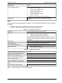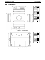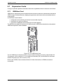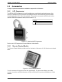
1
VESDA VLI
Product Guide
December 2010
Document: 18500_A1
Part Number: 29674
VESDA by Xtralis
VESDA VLI Product Guide
Intellectual Property and Copyright
This document includes registered and unregistered trademarks. All trademarks displayed are the trademarks of
their respective owners. Your use of this document does not constitute or create a licence or any other right to use
the name and/or trademark and/or label.
This document is subject to copyright owned by Xtralis AG (“Xtralis”). You agree not to copy, communicate to the
public, adapt, distribute, transfer, sell, modify or publish any contents of this document without the express prior
written consent of Xtralis.
Disclaimer
The contents of this document is provided on an “as is” basis. No representation or warranty (either express or
implied) is made as to the completeness, accuracy or reliability of the contents of this document. The manufacturer
reserves the right to change designs or specifications without obligation and without further notice. Except as
otherwise provided, all warranties, express or implied, including without limitation any implied warranties of
merchantability and fitness for a particular purpose are expressly excluded.
General Warning
This product must only be installed, configured and used strictly in accordance with the General Terms and
Conditions, User Manual and product documents available from Xtralis. All proper health and safety precautions
must be taken during the installation, commissioning and maintenance of the product. The system should not be
connected to a power source until all the components have been installed. Proper safety precautions must be taken
during tests and maintenance of the products when these are still connected to the power source. Failure to do so
or tampering with the electronics inside the products can result in an electric shock causing injury or death and may
cause equipment damage. Xtralis is not responsible and cannot be held accountable for any liability that may arise
due to improper use of the equipment and/or failure to take proper precautions. Only persons trained through an
Xtralis accredited training course can install, test and maintain the system.
Liability
You agree to install, configure and use the products strictly in accordance with the User Manual and product
documents available from Xtralis.
Xtralis is not liable to you or any other person for incidental, indirect, or consequential loss, expense or damages of
any kind including without limitation, loss of business, loss of profits or loss of data arising out of your use of the
products. Without limiting this general disclaimer the following specific warnings and disclaimers also apply:
Fitness for Purpose
You agree that you have been provided with a reasonable opportunity to appraise the products and have made
your own independent assessment of the fitness or suitability of the products for your purpose. You acknowledge
that you have not relied on any oral or written information, representation or advice given by or on behalf of Xtralis
or its representatives.
Total Liability
To the fullest extent permitted by law that any limitation or exclusion cannot apply, the total liability of Xtralis in
relation to the products is limited to:
i. in the case of services, the cost of having the services supplied again; or
ii. in the case of goods, the lowest cost of replacing the goods, acquiring equivalent goods or having the goods
repaired.
Indemnification
You agree to fully indemnify and hold Xtralis harmless for any claim, cost, demand or damage (including legal costs
on a full indemnity basis) incurred or which may be incurred arising from your use of the products.
Miscellaneous
If any provision outlined above is found to be invalid or unenforceable by a court of law, such invalidity or
unenforceability will not affect the remainder which will continue in full force and effect. All rights not expressly
granted are reserved.
www.xtralis.com
i
VESDA VLI Product Guide
VESDA by Xtralis
Scope
The VESDA VLI Product Guide provides a comprehensive description of the VLI detector and its
accessories.
This guide introduces the VLI features, technical specifications and gives an understanding of its
components and their function. You will also find instructions on installing, cabling and powering up
the detector.
This guide is for anyone involved with the design, maintenance and purchasing of a VESDA system.
It is assumed that anyone using this product has knowledge and the appropriate certifications from
local fire and electrical authorities.
Document Conventions
The following typographic conventions are used in this document:
Convention Description
Bold
Used to denote: emphasis Used for names of menus, menu options,
toolbar buttons
Italics
Used to denote: references to other parts of this document or other
documents. Used for the result of an action.
The following icons are used in this document:
Convention Description
Caution: This icon is used to indicate that there is a danger to
equipment. The danger could be loss of data, physical damage, or
permanent corruption of configuration details.
Warning: This icon is used to indicate that there is a danger of electric
shock. This may lead to death or permanent injury.
Warning: This icon is used to indicate that there is a danger of inhaling
dangerous substances. This may lead to death or permanent injury.
Contact Us
The Americas
+1 781 740 2223
Asia
+852 2916 8894
Australia and New Zealand
+61 3 9936 7000
Continental Europe
+32 56 24 19 51
UK and the Middle East
+44 1442 242 330
www.xtralis.com
ii
www.xtralis.com
VESDA by Xtralis
VESDA VLI Product Guide
Codes and Standards Information for Air Sampling Smoke Detection
We strongly recommend that this document is read in conjunction with the appropriate local codes and standards
for smoke detection and electrical connections. This document contains generic product information and some
sections may not comply with all local codes and standards. In these cases, the local codes and standards must
take precedence. The information below was correct at time of printing but may now be out of date, check with your
local codes, standards and listings for the current restrictions.
FCC Compliance Statement
This equipment has been tested and found to comply with the limits for a Class B digital device, pursuant to part 15
of the FCC Rules. These limits are designed to provide reasonable protection against harmful interference in a
residential installation. This equipment generates, uses and can radiate radio frequency energy and, if not installed
and used in accordance with the instruction, may cause harmful interference to radio communications. However,
there is no guarantee that interference will not occur in a particular installation. If this equipment does cause
harmful interference to radio or television reception, the user is encouraged to try to correct the interference by one
or more of the following measures; re-orientate or relocate the receiving antenna, increase the separation between
the equipment and receiver, connect the equipment to a power outlet which is on a different power circuit to the
receiver or consult the dealer or an experienced radio/television technician for help.
FDA
This Xtralis product incorporates a laser device and is classified as a Class 1 laser product that complies with FDA
regulations 21 CFR 1040.10. The laser is housed in a sealed detector chamber and contains no serviceable parts.
The laser emits invisible light and can be hazardous if viewed with the naked eye. Under no circumstances should
the detector chamber be opened.
FM Hazardous Applications
3611 Hazardous Approval Warning: Exposure to some chemicals may degrade the sealing of relays used on the
detector. Relays used on the detector are marked “TX2-5V”, “G6S-2-5V” or “EC2-5NU”.
VESDA detectors must not be connected or disconnected to a PC while the equipment is powered in an FM
Division 2 hazardous (classified) location (defined by FM 3611).
FM Approved Applications
The product must be powered from VPS-100US-120, VPS-100US-220 or VPS-220 only.
ONORM F3014
ONORM F3014, transport times for all tubes (including capillaries) must not exceed 60 seconds from any hole. This
means that the predesigned pipe networks that include capillaries cannot be used.
AS1603.8
The performance of this product is dependent upon the configuration of the pipe network. Any extensions or
modifications to the pipe network may cause the product to stop working correctly. You must check that ASPIRE2
approves alterations before making any changes. ASPIRE2 is available from your authorized representative.
AS1851.1 2005
Maintenance Standards. Wherever this document and the AS1851.1 differ, AS1851.1 should be followed in
preference to this document.
www.xtralis.com
iii
VESDA VLI Product Guide
VESDA by Xtralis
Regional Regulatory Requirements and Notices
UL
For open area protection the fire alarm threshold (signal) that initiates an evacuation procedure via the Fire Alarm
Panel must not be set less sensitive than 0.625%/ft. The detector can send this signal via the Fire Alarm Panel
Output signal or the Pre-alarm output signal.
Through validation testing, Underwriters Laboratories Inc. has verified that VESDA ECO gas detectors, when
installed within the sample pipe network, present no significant effects on the smoke detection performance of
VESDA. The use of the ASPIRE2 calculation software is required to verify system design performance with all
devices included in the design.
Product Listings
l
l
UL
ULC
Regional approvals listings and regulatory compliance vary between product models. Refer to www.xtralis.com for
the latest product approvals matrix.
Document: 18500_A1
Part Number: 29674
iv
www.xtralis.com
VESDA by Xtralis
VESDA VLI Product Guide
Table of Contents
1
Introduction
1.1 Features
2
Product Information
2.1 Detector Components
2.2 How the VLI works
2.3 Front Panel
2.4 Communication Ports
2.5 Specifications
2.6 Dimensions
2.7 Expansion Cards
2.8 Accessories
5
5
6
8
9
10
12
13
14
3
Installation
3.1 Mounting
3.2 Wiring
3.3 Powering Up
3.4 Configuration
3.5 Installation Checklist
3.6 Preliminary System Check
17
18
20
25
26
30
31
4
Pipe Network Design
4.1 Design Considerations
4.2 Installation Considerations
4.3 Inlet Pipes
4.4 Managing the Exhaust Air
33
33
33
33
34
5
Operation
5.1 Connecting to the Detector
5.2 Access Levels
5.3 Commands
35
35
37
38
6
Commissioning
6.1 AutoLearn Smoke
6.2 AutoLearn Flow
6.3 Commissioning Smoke Test
41
41
42
42
7
Maintenance
7.1 Set the Detector to Standby
7.2 Remove the Front Cover
7.3 Replacing the Intelligent Filter
7.4 Replacing the Secondary Foam Filter
7.5 Replacing the Aspirator
7.6 Replacing the Chamber Assembly
7.7 Spare Parts
43
43
44
45
46
47
48
49
8
Troubleshooting
8.1 Troubleshooting with Xtralis VSC
8.2 Troubleshooting with an LCD Programmer
8.3 Fault Reporting Through Relays
51
51
51
51
A
Commissioning Forms
A.1 VLI Detector Commissioning Form
A.2 Display/Relay Configuration
53
54
55
www.xtralis.com
3
3
1
VESDA VLI Product Guide
A.3
A.4
A.5
A.6
A.7
B
Glossary
Index
2
Relay Configuration
VESDAnet Interface Card
ASPIRE2 Data
Smoke Test
Air Sampling Test Results
VESDA by Xtralis
55
55
55
56
56
57
59
www.xtralis.com
VESDA by Xtralis
1
VESDA VLI Product Guide
Introduction
The VESDA VLI is an aspirating smoke detector (ASD) that provides very early warning of fire
conditions by drawing air samples through an air sampling pipe network.
The VLI detector is especially designed to operate in harsh and dirty environments. It incorporates
features that specifically address the common challenges of industrial installations, including:
l
l
l
l
high background levels of airborne particles
the need for an IP54 rated enclosure
detector longevity
the need for in-field maintenance
Figure 1-1: VESDA VLI Aspirating Smoke Detector
The detector easily interfaces with fire warning and fire suppression release systems, and can be
integrated into a building management system (BMS).
1.1
Features
The VLI detector contains the following features:
l
l
l
l
l
l
l
l
l
l
l
l
l
l
l
l
l
l
l
l
Area coverage up to 2000m2 (21,500ft2)
Intelligent Filter (patent pending)
Up to four pipes, with a total pipe length of 360m (1200ft)
Wide sensitivity range
AutoLearn™ Smoke and Flow
Clean Air Zero™
Five high intensity status LEDs
Five relays (fire, fault and three configurable) configurable as latching or non-latching
IP54 enclosure
Inertial separator (sub sampling probe)
Ultrasonic individual pipe flow monitoring
Replaceable aspirator, detection chamber and filters
Programmable General Purpose Input (GPI)
Local USB configuration port
BACnet over Ethernet
Optional expansion cards (VESDAnet with monitored GPI)
Referencing (on VESDAnet enabled model)
Event log for up to 18,000 events
Easy mounting through steel support bracket
Xtralis VSC, Xtralis VSM4 and ASPIRE2 software support
www.xtralis.com
3
VESDA VLI Product Guide
1.1.1
VESDA by Xtralis
Intelligent Filter
The Intelligent Filter is fully monitored and provides consistent sensitivity over the entire life of the
detector. The filter significantly reduces the exposure of the internals of the detector to contaminants
in the incoming air while providing consistent sensitivity to smoke. Refer to section 2.2 for further
information.
4
www.xtralis.com
VESDA by Xtralis
2
2.1
VESDA VLI Product Guide
Product Information
Detector Components
The VLI detector contains a range of field-replaceable components.
Legend
A
Front cover
E
Chamber assembly with tertiary
clean air filter
B
Intelligent Filter
F
Aspirator
C
Secondary foam filter
G
Base
D
Electrostatic Discharge (ESD) cover
Figure 2-1: Detector components
Refer to Chapter 7 for further information regarding maintenance scheduling and availability of
spare parts.
www.xtralis.com
5
VESDA VLI Product Guide
2.2
VESDA by Xtralis
How the VLI works
The VLI detector continually samples air from a protected area via a sampling pipe network (A).
Upon entering the detector, the air passes four ultrasonic flow sensors (B), then through the mixer
compartment of the Intelligent Filter (C), where it is split between two pathways. One pathway
carries the majority of the air through the HEPA filter compartment, while the other carries a small
proportion of the air through a separate ultrasonic flow sensor (D). The air recombines in the main
aspirator (F).
Legend
A
Pipe Inlets
B
Ultrasonic Flow Sensors
C
Intelligent Filter
D
Ultrasonic Flow Sensor
E
Manifold
F
Main Aspirator
G
Sampling Probe
H
Secondary Foam Filter
I
Chamber Assembly
J
Chamber Flow Sensor
K
Chamber
L
Tertiary Clean Air Filter
M Auto Zero Aspirator
N
Exhaust
Figure 2-2: Internal airflow example
Note:
The Intelligent Filter is constantly monitored for blockage using the ultrasonic flow sensor in
the unfiltered path (D). The arrangement of four sets of ultrasonic flow sensors at the
detector air inlets (A) and a separate ultrasonic flow sensor in the unfiltered path (D) allows
the detector to measure the split of the airflow ratio as the filter load increases over time.
The detector sets the sensitivity proportionally depending on flow ratio, thus ensuring
consistent and reliable operation over time.
A portion of recombined air sample is then passed through a sampling probe (inertial separator) and
the secondary foam filter (H) which ensures only smoke sized particles are passed into the detection
chamber for analysis. The larger dust particles are unable pass through the probe and filter
arrangement and hence are exhausted out of the detector (N). This eliminates nuisance alarms
caused by larger dust particles and extends the life of the chamber (K). The tertiary clean air filter (L)
provides air to form clean air barriers within the chamber (K), which protects the optical surfaces
from contamination.
When smoke passes through the Chamber (K), it creates light scatter which is detected by the
sensor circuitry. The air sample is measured, and the detector reports smoke levels adjusted
according to the sensitivity ratio determined by the Flow Sensors (B and D). Air is exhausted from
the detector and may be vented back into the protected area (N).
Note:
6
The status of the detector, all alarms, service and fault events, are monitored and logged
with time and date stamps. Status reporting can be transmitted via relay outputs, across
VESDAnet (VN version only) or BACnet.
www.xtralis.com
VESDA by Xtralis
2.2.1
VESDA VLI Product Guide
Clean Air Zero
The Clean Air Zero feature is a process that directly measures the chamber clean air smoke reading.
This will reduce drift in the chamber smoke reading as caused by contamination.
The user can initiate the Clean Air Zero process using Xtralis VSC. It takes less than 60 seconds to
complete, during which time the detector is offline.
Clean Air Zero Process
1. The user executes the Clean Air Zero command in Xtralis VSC.
2. The main aspirator is turned off.
3. The Clean Air Zero aspirator located inside the chamber assembly is turned on. This aspirator
pumps clean air into the Chamber and purges any contaminated air.
4. After a waiting period, to allow the chamber to purge, a smoke reading is taken with clean air
in the chamber. This reading is the new clean air background value.
5. The Clean Air Zero aspirator is turned off and the main aspirator is turned back on.
6. An event indicating that the Clean Air Zero process has taken place is added to the event log.
www.xtralis.com
7
VESDA VLI Product Guide
2.3
VESDA by Xtralis
Front Panel
The VLI detector provides the following information and control capability:
l
l
Status LEDs: Alarm, Pre-Alarm, Disabled, Fault and Power.
Controls: Reset and Disable button.
Figure 2-3: Front Panel Controls and LEDs
Status LEDs
Table 2-1: LED Indicators
LED
Description
Alarm
The Alarm LED is lit when the Fire 1 Alarm threshold is reached.
Pre-Alarm
The Pre-Alarm LED blinks when the Alert threshold is reached.
The Pre-Alarm LED is lit when the Action threshold is reached.
Disabled
The Disabled lamp is lit when the detector is disabled.
Fault
The Fault LED is lit when a fault is detected, when airflow
normalization is being performed or when the Clean Air Zero function
is in progress.
Refer to Chapter 8 for information on troubleshooting.
Power
The POWER LED illuminates when the detector is powered up.
Reset / Disable Button
l
l
l
l
To reset the detector, press this button once.
To disable the unit, press and hold the button for approximately 2 seconds, until the Disabled
LED illuminates.
To re-enable the unit, press and hold the button for approximately 2 seconds, until the
Disabled LED deactivates.
While the detector is disabled, any faults may be cleared by pressing this button once.
The button will not operate if:
l
l
8
a remote reset switch has been fitted to the Reset (GPI) terminals and is set to the Isolate
position; or
the Reset/Disable button has been locked out in the programming.
www.xtralis.com
VESDA by Xtralis
2.4
VESDA VLI Product Guide
Communication Ports
The majority of user operations are performed using software installed on a computer connected to
the detector via one of the communication ports.
The communication ports are located on the main board inside the detector. It is necessary to
remove the front cover from the detector in order access these ports. Refer to section 7.2 for further
information.
USB
The USB port is used for configuration purposes. It allows direct connection between the VLI
detector and a PC or laptop installed with Xtralis VSC. It is not necessary to install USB drivers in
order for the operating system to recognize the detector.
Ethernet
The Ethernet port is used for configuration and/or monitoring purposes. It enables TCP/IP network
connection between the detector and a PC or laptop installed with Xtralis VSC or Xtralis VSM4, or
other BACnet protocol compatible applications.
RS485
The RS485 port is present on the VESDAnet Card on the VESDAnet enabled model, and can be
used for configuration of any device on the VESDAnet. It provides connectivity for the handheld
LCD Programmer or a local PC or laptop. Refer to section 2.8.1 for further information on the LCD
Programmer.
www.xtralis.com
9
VESDA VLI Product Guide
2.5
VESDA by Xtralis
Specifications
Table 2-2: VLI Detector Specifications
Specification
Value
Supply Voltage
18 to 30 VDC
Power Consumption @24 VDC
l
l
Current Consumption
l
l
Normal: 9.6W
Alarm on: 10.8W
Normal: 415mA
Alarm on: 440mA
Dimensions (WHD)
426.5mm x 316.5mm x 180mm
(16.8 in x 12.5in x 7.1in)
Weight
TBA
Operating Conditions
Temperature:
l
l
l
Tested: -10° to 55°C (14°F to 131°F)
Ambient: 0° to 40°C (32° F to 104°F)
Sampled Air: -20° to 60°C (-4° to 140°F)
Humidity:
Storage Temperatures (Non-operational)
l
10-95% RH, non-condensing
l
Up to 2 years (battery life)
Dry (<95% humidity)
0° to 85°C
Must not exposed to sunlight or other radiation sources
l
l
l
Sampling Pipe Network
l
l
l
Pipe Size
l
l
Relays
l
l
l
l
Maximum length per pipe 120m (350ft)
Total pipe length: 360 m (1200 ft)
Pipe Modeling Design Tool: ASPIRE2™
Internal Diameter: 15-21 mm (0.874 inch)
External Diameter: 25 mm (1.05 inch)
5 relays - Fire, Fault, 3x Configurable.
Contacts rated 2A @ 30 VDC.
Programmable to latch or non-latch states
Programmable 0 - 60 sec delay for each relay
IP Rating
IP54 (protection against dust and water mist)
Mounting
Upright or inverted with supplied mounting bracket
Cable Access
4 plastic plugs (2 top, 2 bottom)
Cable Termination
Screw terminal blocks (0.2-2.5 sq mm, 30-12 AWG)
Interfaces
All Detectors:
l
l
USB (Type 2)
Ethernet (RJ45)
VESDAnet enabled detectors:
l
Alarm Range
10
RS485
0.025 to 20.00% obs/m (0.008 to 6.4% obs/ft.)
www.xtralis.com
VESDA by Xtralis
VESDA VLI Product Guide
Specification
Value
Threshold Setting Range
l
Alert: 0.05%–1.990% obs/m
(0.016% - 0.637% obs/ft)
l
Action: 0.1%–1.995% obs/m
(0.032% - 0.638% obs/ft)
l
Fire1 : 0.15 %–2.0% obs/m
(0.048% - 0.64% obs/ft)
l
Fire2: 0.155 %–20.0% obs/m
(0.05% - 6.4% obs/ft)
** Limited to 12% obs/m (4% obs/ft.) in UL mode
Referencing
Reference smoke level source for VESDAnet enabled
detectors.
Notes:
All shipments are factory configured for UL Mode. If the UL Mode is switched OFF the UL listing will
be voided.
l
l
UL Mode = ON: Fire set to 12% obs/m (4% obs/ft.) to comply with UL268
UL Mode = OFF: Fire threshold can be set up to 20% obs/m (6.4%/ft)
Table 2-3: Key Software Features
Event Log
Up to 18,000 events stored on FIFO basis
AutoLearn
l
l
l
Minimum 15 minutes
Maximum 15 days, 23 hrs, 59 minutes
Recommended minimum period 14 days
Thresholds are automatically changed from the previously set
values to the updated values after the AutoLearn process has
completed.
Referencing
Adjustment for external ambient conditions
Four Alarm Levels
Alert, Action (Pre-Alarm), Fire1 (Alarm) and Fire2
Two Fault Warning Levels
Minor Fault and Urgent Fault
Maintenance Aids
l
l
Filter and flow monitoring
Event reporting via VESDAnet, BACnet and event log
Table 2-4: Ordering Information
VESDA VLI without VESDAnet Card
VLI-880
VESDA VLI with VESDAnet Card
VLI-885
Handheld LCD Programmer
VHH-100
Remote LCD Programmer Module
VRT-100
Remote Display Module
VRT-200
Remote VESDAnet Socket Module
VRT-300
Remote Processor Only Module With 7
relays
VRT-500
Remote Display Without Relays
VRT-600
Note:
Refer to section 7.7 for the spare parts list.
www.xtralis.com
11
VESDA VLI Product Guide
2.6
VESDA by Xtralis
Dimensions
mm inch
A
180
7.08
B 426.5 16.8
C 316.5 12.46
D
70.2
2.76
E
45
1.77
F
149
5.87
G
34
1.34
H
60.3
2.37
I
26.7
1.05
J
70.2
2.76
K
105
4.13
L 206.3 8.11
Figure 2-4: Front Dimensions
mm inch
A 426.5 16.8
B 316.5 12.46
C
75
2.95
D 88.25 3.47
E
250
9.84
F
96.3
3.8
G 115.2 4.54
H
105
4.13
Figure 2-5: Rear Dimensions
12
www.xtralis.com
VESDA by Xtralis
2.7
VESDA VLI Product Guide
Expansion Cards
A range of optional expansion cards that enhance the capabilities of the VLI detector can be fitted.
2.7.1
VESDAnet Card
VESDAnet is a proprietary communications protocol which is used on a network that connects the
VESDA range of smoke detectors, displays, programmers and remote units and enables them to
communicate.
A VESDAnet network allows:
l
l
l
configuration and monitoring of devices from a central computer.
connection to a reference detector.
connection to additional accessories such as remote displays.
The VESDAnet enabled VLI detector (VLI-885) can join a VESDAnet network when the optional
VESDAnet expansion card is installed.
Figure 2-6: VLI VESDAnet Card
The VLI VESDAnet Card also includes a 15-pin socket for directly connecting a hand-held LCD
Programmer (refer to section 2.8.1) or a High Level Interface (HLI), and a socket for monitored
General Purpose Input (refer to section 3.2.5).
Refer to the VESDA Communications Guide for further information on VESDAnet network
connectivity.
www.xtralis.com
13
VESDA VLI Product Guide
2.8
VESDA by Xtralis
Accessories
A range of optional accessories are available to augment the VLI detector.
2.8.1
LCD Programmer
The VESDA LCD Programmer is used for configuring, commissioning and maintenance of the
devices on VESDAnet. It is connected via VESDAnet and can be mounted at a remote location.
A hand-held model (VHH-100) is also available. This model is connected to a DB9 socket on the
optional VESDAnet expansion card (refer to section 2.7.1).
Legend
A
LCD Display
B
Keys
Figure 2-7: Hand-held LCD Programmer
Refer to the LCD Programmer Product Guide for further details.
2.8.2
Remote Display Module
The Remote Display Module provides real-time indication of the status of a VLI detector and a single
zone.
Figure 2-8: Remote Display Module
The unit contains a 20-segment vertical bar graph display, a 2 digit numeric display, an audible
sounder, clear alarm and fault indicators, and can be mounted in a remote mounting box or 19 inch
subrack.
14
www.xtralis.com
VESDA by Xtralis
l
l
l
l
l
l
VESDA VLI Product Guide
Smoke levels are continuously shown on the bar graph display where each illuminated
segment indicates the current level of detected smoke.
The top segment of the bar graph indicates the Fire 1 smoke threshold level and each
segment below that level represents 1/20 of the Fire 1 smoke threshold level.
The Fire 1, Action and Alert smoke threshold indicators provide a visual representation of the
programmable alarm thresholds, showing how close the smoke level is to triggering the next
level of alarm.
Fault conditions are indicated by a series of LEDs and an audible tone.
The numerical readout can show either the current smoke level in % obscuration/m (%
obscuration/ft) or the Fire 1 threshold in % obscuration/m (% obscuration/ft).
Four buttons enable users to reset, isolate or silence the detector and control the mode of the
remote display module. These buttons can be locked out.
www.xtralis.com
15
VESDA VLI Product Guide
VESDA by Xtralis
This page is intentionally left blank.
16
www.xtralis.com
VESDA by Xtralis
3
VESDA VLI Product Guide
Installation
The VLI detector is shipped with all the components necessary for installation with the exception of
pipe and associated materials.
Components include:
l
l
l
l
l
1 VLI detector
1 Mounting bracket.
1 End of Line resistor with units factory fitted with VESDAnet Card
Multilingual Installation Sheet
this Product Guide
Check all components for damage and refer any concerns to your authorized representative.
Additional Requirements
Depending on the nature of the installation, it may be necessary to acquire the following items:
l
l
Screws and inserts for the mounting bracket appropriate for the installation location
USB Interface Lead if configuration of the detector is to be done via the USB interface
Figure 3-1: Type A to Type B USB Interface Lead
www.xtralis.com
17
VESDA VLI Product Guide
3.1
VESDA by Xtralis
Mounting
The VLI detector can be mounted in an upright or inverted position. Do not mount the detector with a
sideways orientation as shown in Figure 3-2 below.
Figure 3-2: Sideways orientation
Ensure the mounting surface is flat. This will permit an air tight seal to be achieved between the
sampling pipe and the tapered air ports on the detector.
Ensure that there is sufficient clearance to mount the detector, noting the location of air sampling
pipes and cable entry points. Due to the rigid nature of the plastic pipe, installation must provide for
sufficient movement in all pipework (air inlet, air exhaust and cable pipes) to allow pipe ends to be
easily fitted and removed.
Figure 3-3: Mounting location
Mount the Detector
1. Horizontally align the mounting bracket (A) and place the flat side flush against the surface.
Use appropriate fasteners (B) to secure the bracket.
Legend
A
Mounting bracket
B
Fasteners
C
Locking Mechanism
D
Hooks
Figure 3-4: Mounting Bracket
2. Ensure that the locking mechanism (C) is bent outwards, as shown below in Figure 3-5.
3. Place the four slots located at the rear of the detector onto the hooks (D) of the mounting
bracket.
4. Slide the unit downwards onto the hooks (D) until the locking mechanism (C) clicks.
18
www.xtralis.com
VESDA by Xtralis
VESDA VLI Product Guide
Legend
A
Detector
B
Mounting bracket
C
Locking Mechanism
Figure 3-5: Mounting the detector
www.xtralis.com
19
VESDA VLI Product Guide
3.2
VESDA by Xtralis
Wiring
The screw type terminals located on electrical terminals within the VLI detector will accept wire sizes
from 0.2 mm2 to 2.5 mm2 (30 – 12 AWG).
Refer to Codes and Standards Information for Air Sampling Smoke Detection on page iii for code
specific requirements.
Refer to the VESDA System Design Manual for cabling details.
Caution:
3.2.1
Electrostatic discharge (ESD) precautions need to be taken prior to removing the front
cover from the detector in order to prevent damage to sensitive electrical components
within the VLI.
Power Source
There are two sets of power terminals on the main board. Connect to a 24 VDC power supply to the
PWR IN socket, and if required loop out to another detector via the PWR OUT socket.
The detector will not operate if the power supply polarity is reversed.
Caution:
Operating the detector when DC supply voltage is outside the specified voltage range
may cause damage to internal components. For further information refer to the Product
Specifications on page 10.
Figure 3-6: Wire connection details for power terminals
Power to Multiple Detectors
Up to 8 detectors may be daisy chained to the same power supply by connecting the PWR OUT
power passthrough socket to the PWR IN socket on each subsequent detector.
Figure 3-7: Multiple Detectors powered by a single power supply
20
www.xtralis.com
VESDA by Xtralis
VESDA VLI Product Guide
Compliance
It is recommended that the power supply be compliant with local codes and standards required by
the regional authority. For code-specific information, see Codes and Standards Information for Air
Sampling Smoke Detection on page iii.
3.2.2
VESDAnet
VESDAnet is a bidirectional data communication network between connected VESDA devices.
VESDAnet connectivity is available on the VESDAnet enabled VLI detector (VLI-885). Refer to
section 2.7.1 for further information.
It is recommended that RS 485 (Belden 9841 - 120 Ohm) twisted pair cables, or similar cables be
used for including the devices in the network.
The network cables are terminated at the VESDAnet A and B Terminals on the VESDAnet card.
Cabling from one VESDA device is brought into the detector at one terminal and looped out to
another device on VESDAnet from the other terminal.
Notes:
l
l
Connection between devices should be from A to B. Avoid using A to A or B to B.
The polarity of the data wires must be maintained throughout the network.
Figure 3-8: Example closed loop VESDAnet network
The VLI-885 detector is shipped with the VESDAnet A and B terminals looped. Remove this loop
prior to connecting the detector to the VESDAnet. If the detector is not to be networked with other
devices, then do not remove this loop.
Figure 3-9: Closed loop for standalone detectors with VESDAnet capability
Note:
Refer to the VESDA Communications Guide for further information.
www.xtralis.com
21
VESDA VLI Product Guide
3.2.3
VESDA by Xtralis
Relays
The relays, located on the main processor card, interface to Fire Alarm Control Panels (FACP) to
communicate faults, alarms and isolate states.
Fault and Fire1 Relay Terminals
Fault (Trouble) and Fire1 (Alarm) relay terminals are located on the main board inside the detector.
The Fault relay is energized during normal operation while the Fire relay is only energized when a
Fire is detected. The operation of the relays are summarized in the following table.
Table 3-1: Fault and Fire Relay Operation
FAULT Relay
Normal Operation
(Energized)
Fault
or unpowered state
FIRE Relay
Normal Operation
(De-energized)
Fire
Programmable Relays
The three additional relays can be programmed using Xtralis VSC software or the LCD
Programmer. Refer to the Xtralis VSC Online Help or LCD Programmer Product Guide for details.
3.2.4
Unmonitored General Purpose Input (GPI)
The GPI is a programmable input which can be configured to initiate a number of different actions including, by default, a Remote Reset function.
Notes
l
l
When the detector is isolated or de-isolated via the GPI, the status cannot be changed
through the normal isolate/de-isolate functions of the Display Module or the LCD
Programmer.
When the night-time thresholds are invoked via the GPI, it overrides the clock settings for daystart and night-start.
The GPI requires a voltage supply between 5V and 30 VDC from the connected device in order to
operate. The input is isolated from the system by an opto-coupler device.
3.2.5
Monitored General Purpose Input (GPI) Wiring
Monitored GPI is available in units fitted with the VESDAnet card. It can be used to monitor the
detector power supply.
With monitored GPI, the detector monitors the GPI for open or short circuit faults when the GPI
function is set to any value except None.
When the GPI function parameter is set to external, the detector indicates an external equipment
fault condition by monitoring the line impedance. An End of Line (EOL) resistor is supplied with the
product and must be assembled in parallel with the device to be monitored.
The EOL resistor provides a known termination to the external equipment, this allows the VLI
detector to identify open or short circuits.
22
www.xtralis.com
VESDA by Xtralis
3.2.6
VESDA VLI Product Guide
Typical Wiring to Fire Alarm Control Panel (FACP)
The diagram below shows the correct way to wire VESDA detectors to a conventional fire alarm
control panel (FACP). It also shows where an End Of Line (EOL) resistor is correctly installed.
Figure 3-10: Typical wiring to a fire panel with EOL
3.2.7
Typical Wiring to Address Loop Module
This wiring example is for wiring VESDA detectors to a typical Input/Output Loop module 3 inputs 1
output. These are example drawings. Refer to the appropriate product manual for the exact wiring
details of the third party equipment.
Figure 3-11: Input/Output Loop Module with EOL
www.xtralis.com
23
VESDA VLI Product Guide
3.2.8
VESDA by Xtralis
Specify Backup Battery
In the event of a mains power supply disruption, the VLI detector runs on a backup battery. The size
of the battery is determined by:
l
l
l
l
l
local codes and standards
the total power required by the system
back up time required
allowance for reduction in capacity with age
expected temperature variations
Note:
It is recommended that batteries be inspected and changed as per manufacturer’s
specifications or as per local codes and standards.
To facilitate the calculation of the backup battery size, a Battery Calculation Sheet is included below.
Table 3-2: Calculating the size of backup battery
Equipment
Normal loads @ 24 V DC
Load mA
Qty
Total
Full alarm load @ 24 V DC
Load mA
Detector
340
390
Remote Display
90
110
Remote Programmer
50
110
(backlight off)
(backlight on)
Hand-held Programmer 50
Total
110
(backlight off)
(backlight on)
System Relay Module 60
Other 24V Loads
Qty
105
Total
mA
Total
mA
X
Standby Hours
X
Alarm Hours
=
Standby Capacity
Alarm Capacity
Total Capacity =
Standby + Alarm
Divided by 1000 for
Standby Capacity
Multiply by battery
factor X1.25
Note:
24
If monitored GPI terminals are connected to the power supply and configured for external fault,
the aspirator speed will be maintained for one hour after the loss of mains power, after which the
aspirator speed will be limited to 3000 rpm to conserve power.
www.xtralis.com
VESDA by Xtralis
3.3
VESDA VLI Product Guide
Powering Up
After installing the detector it is necessary to power up the system. This takes approximately 15
seconds.
The VLI detector is an "always on" device which is activated by applying powered cabling to the
power input terminal on the main board. This process must only be performed by Xtralis accredited
personnel.
If the system fails to power up, check all power wires are secured to their terminals and the polarities
of the power wires are correctly terminated.
On power up:
l
l
l
The Power LED illuminates.
The aspirator starts up and air is felt flowing out of the exhaust port
If there is a fault, the Fault LED illuminates.
It is normal for the detector to display troubles immediately after the first power up. Reset the
detector by pressing the reset button on the front cover of the detector to unlatch the relays and fault
LED. Any remaining faults will cause the Fault LED to illuminate. Proceed with the preliminary
system check.
www.xtralis.com
25
VESDA VLI Product Guide
3.4
VESDA by Xtralis
Configuration
The VLI detector can be configured using Xtralis VSC software installed on a direct or network
connected PC.
3.4.1
Default Settings
Table 3-3: Default Settings
Parameter
Default Values
Range
Access
Level
Minimum
Maximum
Event Log - Events
l
Smoke Level
Enabled
n/a
n/a
Adm
l
Alarms
Enabled
n/a
n/a
Adm
l
Faults
Enabled
n/a
n/a
Adm
l
User Action
Enabled
n/a
n/a
Adm
Thresholds
l
Alert
0.2% obs/m
(0.064% obs/ft)
0.05% obs/m
(0.016% obs/ft)
1.990% obs/m
(0.637% obs/ft)
Adm
l
Action
(Pre-Alarm)
0.3% obs/m
(0.096% obs/ft)
0.1% obs/m
(0.032% obs/ft)
1.995% obs/m
(0.638% obs/ft)
Adm
l
Fire1
(Alarm)
0.4% obs/m
(0.128% obs/ft)
0.15% obs/m
(0.048% obs/ft)
2.0% obs/m
(0.64% obs/ft)
Adm
l
Fire2
2.0% obs/m
(0.64% obs/ft)
0.155% obs/m
(0.05% obs/ft)
20.0% obs/m
(6.4% obs/ft**)
Adm
Alarm Delays
10 Seconds
0 Seconds
60 Seconds
Adm
Delay Times
Simultaneous
Simultaneous
Cumulative
Adm
Instant Fire
Disabled
Enabled
Disabled
Adm
Two Seconds
11:59:58
Adm
Adjust to suit
environment
Adjust to suit
environment
Adm
Adjust to suit
environment
Adjust to suit
environment
Adm
Change-over Times:
l
l
Day
Night
Weekend
l
l
07:00:00
19:00:00
Saturday & Sunday
Holidays
l
l
First Day
Last Day
l
l
1-Jan-90
1-Jan-90
Smoke Change:
l
l
Change by:
Min. Interval
l
l
AutoLearn
0.02% obs/m
(0.006%obs/ft.)
2 seconds
14 days
0 hours
0 minutes
l
l
0.02% obs/m
(0.006%obs/ft.)
2 seconds
0 days
0 hours
15 minutes
l
l
0.2% obs/m
Adm
(0.064%obs/ft.)
10 seconds
15 days
23 hours
59 minutes
Adm
** In default "UL mode", maximum sensitivity is limited to 4%/ft
26
www.xtralis.com
VESDA by Xtralis
VESDA VLI Product Guide
Parameter
Default Values
Range
Minimum
Maximum
Access
Level
Air flow Thresholds:
l
l
l
l
l
High Urgent
High Minor
Low Minor
Low Urgent
Delay
l
l
l
l
l
150%
130%
70%
50%
0 seconds
l
l
l
l
l
105%
105%
25%
25%
0 seconds
l
l
l
l
l
200%
200%
95%
95%
60 seconds
Adm
Secondary Filter
Service Interval
1460 days (4 years)
1 Day
3655 days (10 years)
Adm
UL Version
On
Selectable
Selectable
Adm
VESDAnet enabled detectors
Reference detector:
l
Zone No.
l
l
Reference
l
l
Dilution Delay
l
255
100%
2 minutes
l
15 seconds
A
45 seconds
None
l
l
l
Selectable
1%
0 minutes
l
10 seconds
n/a
40 seconds
n/a
l
l
l
Selectable
100%
15 minutes
Adm
45 seconds
n/a
60 seconds
n/a
DST
Communications:
l
l
l
l
3.4.2
Network Delay
Preferred Port
Health Check
Open - ended
l
l
l
l
l
l
l
l
l
l
Relay Assignments and Conditions to Change States
Relays 1 and 2 are fixed to Fire1 (Alarm) and Fault respectively.
Relays 3, 4 and 5 are fully configurable. For example, relay 3 could be configured to Alert, Fire2 or
Minor Fault.
Table 3-4: Relay assignments and conditions to change state
Relay #
Default
State changes
Latch
1
Fire1 (Alarm) Energizes when an alarm is initiated.
Unlatched
2
Fault
De-energizes when a fault is detected.
Latched
n/a
Configurable
Configurable
3,4,5
www.xtralis.com
27
VESDA VLI Product Guide
3.4.3
VESDA by Xtralis
Unmonitored General Purpose Input (GPI) Functions
The unmonitored GPI can be configured to initiate a number of different actions - including, by
default, a Remote Reset function.
The GPI can be configured through Xtralis VSC or through the 'Miscellaneous’ screen menu of the
LCD programmer. Refer to the Xtralis VSC Online Help or LCD Programmer Product Guide for
further details.
Refer to section 3.2.4 for further information on GPI wiring.
Table 3-5: GPI Functions
Function
State Change
External Reset
Detector Reset when ≥ 5 VDC is at this
terminal.
Mains OK
The detector monitors the state of the
external power supply and responds to the
following conditions.
l
l
Standby Mode
Mains OK ≥ 5 VDC at this terminal.
Mains Fail ≤ 2 VDC at this terminal.
The detector Isolates and the aspirator
turns OFF when ≥ 5 VDC is at this
terminal.
Note:
No Alarms can be generated in
this state
Isolate
The detector isolates when the voltage
rises above 5 VDC and de-isolates when
the voltage falls below 5V.
Use Night-time
Threshold
The detector switches over from day-time
to night-time thresholds when ≥ 5 VDC are
at these terminals.
Reset + Isolate
While power is applied to the GPI the
detector is isolated. In addition, the
disconnection or connection of power to
the GPI resets the unit.
l
l
Inverted Reset
≥ 5 VDC detector isolates.
≤ 2 VDC detector reset.
This is the reverse of the normal reset
function.
l
l
≤ 2 VDC detector reset.
≥ 5 VDC normal operating mode.
Notes:
l
l
l
28
The signal voltage into the GPI terminals must be between 5 to 30 VDC.
When the detector is isolated, de-isolated or set to standby as a GPI function, the status
cannot be changed through the normal isolate/de-isolate/standby functions of the Display
Module or the LCD Programmer.
When the night-time threshold is configured as a GPI function, it overrides the clock settings
for day-start and night-start.
www.xtralis.com
VESDA by Xtralis
VESDA VLI Product Guide
When using the standby or remote isolate options it is recommended that all displays on VESDAnet
are configured to have the Isolate button locked out. When programming the display through the
LCD Programmer choose Isolate Disabled from the Button Lockout menu.
www.xtralis.com
29
VESDA VLI Product Guide
3.5
VESDA by Xtralis
Installation Checklist
Site Name
Address
Detector Serial Number(s) and Date of
Manufacture
Name of Installer
Signature
Date
Perform the following checks listed below to ensure that all the necessary items are completed
before handing over to a commissioning engineer.
Installation Checks
Yes No
Were the detector and the mounting bracket intact in the box?
Is the detector securely locked onto its mounting bracket?
Are the sampling air pipes firmly connected to the air inlet ports? Ensure that
the pipes are NOT glued.
Have the power wires been connected to the correct terminals on the
detector?
If required, has the end of line resistor been connected?
Have the alarm and fault signaling wires been terminated to the correct
terminals of the detector?
Has the plug at the exhaust port been removed? Ensure that the exhaust
pipe (if fitted) is NOT glued.
Has the front cover been fitted correctly?
Is the air sampling pipework installed and checked as per the site plans?
Are the VESDAnet terminals looped back on a standalone VESDAnet
enabled detector? Refer to section 3.2.2.
Is the Intelligent Filter installed and its lever locked down?
Is the secondary foam filter installed?
Table 3-6: Installation Checklist
30
www.xtralis.com
VESDA by Xtralis
3.6
VESDA VLI Product Guide
Preliminary System Check
A preliminary system check is required after installing the VLI detector, before it is commissioned for
use. The check can be conducted by connecting the detector to a LCD Programmer or using the
Xtralis VSC software. The preliminary systems check includes:
l
l
l
l
For networked detectors, conducting a communications check .
Configure the "pipes in use" setting.
Normalizing the air flow.
Conducting a basic pass/fail smoke test.
For details on preliminary systems check refer to the LCD Programmer or the relevant software
documentation.
Refer to the LCD Programmer and Commissioning Guides for further details.
www.xtralis.com
31
VESDA VLI Product Guide
VESDA by Xtralis
This page is intentionally left blank.
32
www.xtralis.com
VESDA by Xtralis
4
VESDA VLI Product Guide
Pipe Network Design
The Pipe Network should be designed by trained personnel, and verified using the ASPIRE2
software.
4.1
Design Considerations
The following points should be considered when designing a pipe network for the VLI detector:
l
The detector requires a minimum total airflow of 40 liters per minute, and a minimum of 20
liters per minute per pipe.
Refer to the VESDA Pipe Network Design Guide for best design practices.
4.2
Installation Considerations
The following points should be considered when installing sampling pipe:
l
l
l
l
l
l
l
l
l
l
minimize flexing in sampling pipes by supporting the pipe every 1.5m (5ft) or less, or at a
distance described in local codes and standards.
evenly arrange the sampling pipe network over return air grilles.
sampling pipe fits firmly into the tapered detector port, DO NOT glue this connection.
allow sufficient movement at the detector to permit pipe removal for maintenance.
keep the exhaust pipe as short as possible to minimize airflow resistance in the pipe.
pipe ends must be made smooth for bonding.
sampling holes must be drilled in line and perpendicular to the pipe.
sample holes must be clear of rough edges and debris.
pipes are free of debris.
all joints must be bonded except the endcaps and pipes entering the detector.
Notes:
l
l
l
In protected areas sampling holes should face into the direction of airflow, or point downwards
in static airflow situations.
Keep the sampling holes evenly spaced.
For code-specific information, see Codes and Standards Information for Air Sampling Smoke
Detection on page iii.
Refer to the Pipe Network Installation Guide for best installation practices.
4.3
Inlet Pipes
The VLI detector supports up to four sampling pipes.
The inlets in the pipe inlet manifold are tapered such that they receive both 25 mm (1 in) or IPS 3/4
inch outer diameter pipes.
Each air inlet port allows maximum insertion of the sampling pipe to a depth of 15 mm. (0.60 in). This
prevents the sampling pipes from damaging the flow sensors. While connecting the detector to the
pipe network:
l
l
l
l
l
Note:
Ensure a minimum length of 500mm (19.7in) of straight pipe before terminating the pipes at
the air inlet ports of the detector.
Square off and de-burr the end of the sampling air pipes, ensuring the pipes are free from
debris.
Determine the Air Inlet Ports to be used. Refer to Table 4-1 below for details.
Remove the plugs from only those Air Inlet Ports intended for use.
Insert the pipes into the pipe inlet(s) ensuring a firm fit.
DO NOT glue the inlet pipes to the pipe inlet manifold.
www.xtralis.com
33
VESDA VLI Product Guide
VESDA by Xtralis
When configuring the detector ensure that the correct pipes in use are selected:
Table 4-1: Preferred use of pipe inlet ports
No. of Pipes
Preferred Pipe Inlet Port to use
Pipe 1
1
Pipe 2
Pipe 3
Inlet 2 or 3
Inlet 2 or 3
Pipe 4
2
3
Inlet 1 or 4
Inlet 1 or 4
4
Figure 4-1: Pipe inlet port numbering
For code-specific information, see Codes and Standards Information for Air Sampling Smoke
Detection on page iii.
4.4
Managing the Exhaust Air
Air is expelled from the detector via the exhaust port at the bottom of the unit enclosure.
The air exhaust port is tapered to accept standard pipes of OD 25 mm (ID 21 mm) or IPS ¾ inch and
to provide an airtight seal. Remove the exhaust port plug and if required, connect an outlet pipe to
the exhaust manifold. DO NOT glue this pipe to the exhaust manifold as this will void the warranty.
Where the detector is located outside the protected area, it may be necessary to return the exhaust
air to the protected environment. For example, where pressure differences exceed 50 Pa, or where
hazardous substances are present inside the protected area. Return air pipes need to be as short as
possible to minimize the effect of airflow resistance in the return air pipe network.
34
www.xtralis.com
VESDA by Xtralis
5
VESDA VLI Product Guide
Operation
Once the VLI detector has been commissioned, it will report alarms and faults according to the
parameters defined during installation.
The procedures below describe how to define a connection to the detector within Xtralis VSC.
5.1
Connecting to the Detector
Xtralis VSC supports connecting to a VLI detector via a range of connection mechanisms and
communication protocols. Connection methods are defined and saved for future use within the
Connection Manager.
To define a connection to a networked or standalone VLI detector, follow this procedure:
1. Select Connection | Manager from the menu system.
The Connection Manager dialog is displayed.
Figure 5-1: Connection Manager
2. Select Add.
The Add Connection dialog is displayed.
Figure 5-2: Add Connection
3. Select the BACnet connection option, then select Next.
www.xtralis.com
35
VESDA VLI Product Guide
5.1.1
VESDA by Xtralis
Creating a USB Connection
1. Open the VLI detector and connect the USB cable from the USB socket on the main board
inside to a PC or laptop located near the detector with the Xtralis VSC software installed.
Refer to Chapter 7 for further information on opening the detector.
2. Follow the steps in section 5.1.
3. Select BACnet from the Add Connection dialog box (Figure 5-2).
4. Select USB, then select Next (Figure 5-3).
5. Select the detector type from the list of available detectors, then select Next.
6. Enter a unique BACnet Device ID, then select Next.
7. Enter a unique name for the device, then select Finish.
Figure 5-3: Select USB
5.1.2
Creating an Ethernet (BACnet/IP) Connection
1.
2.
3.
4.
Follow the steps in section 5.1.
Select BACnet from the Add Connection dialog box (Figure 5-2).
Select Ethernet (BACnet/IP), then select Next (Figure 5-4).
Enter a unique IP address, then select Next. If the detector is being connected to a corporate
network, this address may need to be provided by the network administrator.
5. Enter a unique BACnet Device ID, then select Next.
6. Enter a unique name for the device, then select Finish.
Figure 5-4: Select Ethernet (BACnet/IP)
Note:
36
For specific information relating to network configuration, refer to the VESDA
Communications Guide.
www.xtralis.com
VESDA by Xtralis
5.1.3
VESDA VLI Product Guide
Creating a VESDAnet Connection
1. Follow the steps in section 5.1.
2. Select VESDAnet from the Add Connection dialog box (Figure 5-2).
3. Select the COM port associated with the High Level Interface (HLI) and click on the Next
button.
4. Enter the name you want to identify the connection with in the Name field and click on the
Finish button.
Note:
For specific information relating to VESDAnet configuration, refer to the VESDA
Communications Guide.
5.2
Access Levels
When accessing the VLI detector via Xtralis VSC or LCD Programmer, there are three user levels;
DST, ADM and USER. It is necessary to log in using a four digit PIN code.
User Level
Access Level
Functional Authorization
USR
Low
This is the USER or the OPERATOR level.
The user can view the event log, change the
date and the time. They can also perform
selected zone control functions.
ADM
High
At the ADMINISTRATOR level access is
available to most functions. These include
setting alarm thresholds, normalizing air
flows, reset filter, and defining the relay
configuration.
DST
Absolute
The DISTRIBUTOR level allows unlimited
access to all the system commands and
parameters.
Table 5-1: User Access Levels
The default PIN for each level of user is set at the factory. The distributor has access to the PINs for
each level. PIN numbers are disclosed to authorized personnel attending accredited training
courses.
After logging in the user has the option to change the default PIN. To guard against unauthorized
access, if someone enters an incorrect PIN number three times they will not be allowed another
attempt for ten minutes
www.xtralis.com
37
VESDA VLI Product Guide
5.3
VESDA by Xtralis
Commands
The following commands are able to be issued to the detector:
Command
Description
Execute From
Detector
Return to Factory Defaults
Restores the configuration of the detector to the
initial factory default values.
Accept Factory Defaults
Applies the factory default settings to the detector.
Disable
Disables all the output relays associated with the
detector.
Standby
Turns off the aspirator and stops all signaling.
Enable
Enables all the output relays associated with the
detector.
Reset
Unlatches all latched alarms and faults, and
returns relays to their normal state. Reset does not
apply to the Isolate condition.
Normalize Air Flow
Starts the air flow normalization process for the
selected detector.
VSC
The normalization process determines the
reference flow rate.
The detector can be in normal or disabled mode,
but not standby mode.
While the aspirator is turned off during the process,
the detector will not register smoke levels from the
protected environment.
A fault will be generated if the process fails.
Start AutoLearn Smoke
In Xtralis VSC you will be prompted to set the
period of time that the environment is monitored to
allow the system to decide what smoke thresholds
are most appropriate.
It is recommended to set the smoke thresholds a
little higher than expected before starting the
AutoLearn to prevent any unnecessary triggering of
alarms. When the AutoLearn has finished, the
levels are overwritten.
Cancel AutoLearn Smoke
Cancel the AutoLearn Smoke process.
Smoke thresholds will remain at levels set prior to
commencing AutoLearn Smoke.
Reset Aspirator
Reset the smoke hours for the aspirator.
Reset Intelligent Filter
Reset the Intelligent Filter status information after
installing a replacement.
Reset Secondary Foam Filter
Reset the Secondary Foam Filter status
information after installing a replacement.
Rebuild Zone List
Send a command to detectors on the same
VESDAnet for them to rebuild the list of display
modules that are assigned to each detector.
Clear Event Log
Remove all entries from the Event Log.
38
www.xtralis.com
VESDA by Xtralis
Command
VESDA VLI Product Guide
Description
Execute From
Detector
Start Fault Test
Generate a fault on the detector and de-energizes
the fault relay (Relay 2).
Start Alarm Test
Simulate full scale smoke level and initiates all
alarm activity.
VSC
Alarm relays will energize unless isolated.
Start Air Flow Fault Test
Test the air flow sensing system by shutting down
the aspirator for 30 seconds.
Relay Test
Test the available relays.
View Current Air Flow
View the current airflow.
Monitor Filter
Display filter status.
Clean Air Zero
Measure chamber background.
Note:
www.xtralis.com
This command will shut down the
aspirator for up to a minute.
39
VESDA VLI Product Guide
VESDA by Xtralis
This page is intentionally left blank.
40
www.xtralis.com
VESDA by Xtralis
6
VESDA VLI Product Guide
Commissioning
The VLI has been designed to simplify commissioning processes. The AutoLearn function allows the
unit to assess its environment and setup appropriate alarm and flow thresholds.
The detector is programmed using Xtralis VSC software or LCD Programmer via VESDAnet.
Note:
Detectors should be commissioned with a smoke test.
Prior to commissioning the detector, check:
1. That the power is connected and on.
2. That the pipe network is clean and correctly fitted with all joints correctly seated and sealed
(except the endcaps and the pipe which enters the detector which must not be glued).
It is important that the protected area is working under normal operating conditions when operating
the AutoLearn processes.
For code-specific information, see Codes and Standards Information for Air Sampling Smoke
Detection on page iii.
6.1
AutoLearn Smoke
AutoLearn Smoke is initiated within Xtralis VSC or the LCD Programmer.
During the AutoLearn Smoke process, the detector determines the average smoke and peak smoke
obscuration levels and sets suitable alarm thresholds for the operating environment. This process
will minimize nuisance alarms due to normal environment smoke variations.
During the learning cycle, alarm conditions can be reported. If an alarm condition occurs, AutoLearn
will not complete its cycle. In this situation the user must restart the AutoLearn process. If AutoLearn
is halted, the alarm thresholds will be left at the previous settings.
Conditions experienced during learning are assumed to be representative of normal operating
conditions.
The AutoLearn Smoke learning times range from above 15 minutes to 15 days, with the default
being set to 14 days.
If AutoLearn is running during the changeover period from Day to Night Thresholds, make sure that
AutoLearn runs for at least an hour in both the Day and Night periods.
Table 6-1: AutoLearn Smoke range
Alarm Level
Alert
AutoLearn Smoke Range
0.025%–1.990% obs/m (0.008% - 0.637% obs/ft)
Action (Pre-Alarm) 0.025%–1.995% obs/m (0.008% - 0.638% obs/ft)
Fire1 (Alarm)
0.025 %–2.0% obs/m (0.008% - 0.64% obs/ft)
Fire2
0.025 %–20.0% obs/m (0.008% - 6.4% obs/ft)
For code-specific information, see Codes and Standards Information for Air Sampling Smoke
Detection on page iii.
www.xtralis.com
41
VESDA VLI Product Guide
6.2
VESDA by Xtralis
AutoLearn Flow
AutoLearn Flow process is initiated within Xtralis VSC.
During the AutoLearn Flow process, the detector determines the average and peak air flow levels
monitored over time and sets suitable air flow thresholds that will not give rise to nuisance flow faults
due to normal flow variations (such as might arise through air-conditioning related nuisance faults).
The system will normalize the flow and then monitor the flow trend to set the flow fault thresholds.
During the learning cycle, flow faults can be reported. If a flow fault is reached, AutoLearn will not
complete its cycle. In this situation the user must restart the AutoLearn process. If AutoLearn is
halted, the flow thresholds will be left at the previous settings.
Conditions experienced during learning are assumed to be representative of normal operating
conditions.
The AutoLearn Flow learning times range from 15 minutes to 15 days, with the default being set to
14 days.
6.3
Commissioning Smoke Test
It is recommended that a smoke test be carried out to prove the integrity of the pipe network, to
demonstrate that the system is working and to measure the transport time to the detector.
This test involves introducing a smoke sample at the furthest sampling hole and then measuring the
time taken for the smoke to travel to the detector. Results are logged and compared to subsequent
tests to note variations of the system.
Refer to the VESDA Commissioning Guide for details of the commissioning smoke test.
42
www.xtralis.com
VESDA by Xtralis
7
VESDA VLI Product Guide
Maintenance
To maintain the VLI detector at its peak performance level, the recommended maintenance
schedule shown in Table 7-1 below should be followed.
Table 7-1: Recommended maintenance schedule for the VLI detector
Maintenance Check
Quarterly
Six
Monthly
Annual
Biennial
Quadrennial
Power Supply
Check Pipe Network
Pipe Integrity Smoke Test
Check Pipe Flow
Clean Sampling Point
Flush Pipe Network
Replace Intelligent Filter
Replace Secondary Foam
Filter
Notes:
l
l
Maintenance can be conducted by the original installer or an authorized distributor or service
contractor.
The required frequency of maintenance checks may vary depending upon local codes and
standards and the environment of the installation.
Caution:
While the detector or zone is isolated, no fire warnings will be annunciated by the
detector. Prior to any maintenance or testing:
l
l
l
7.1
Inform appropriate supervising authority about the risk associated with isolating a
detector or zone.
Check to see if the detector is also being used by a third party.
Ensure that any ancillary devices dependent on the detector are isolated before work
commences.
Set the Detector to Standby
To set the detector to standby, press and hold the Reset / Disable button for 2 seconds. The
Disabled LED will illuminate and the aspirator will turn off.
To re-activate the unit, press and hold the button for 2 seconds.
While the detector is in standby mode, any faults may be cleared by pressing this button once.
The button will not operate if:
l
l
a remote reset switch has been fitted to the Reset (GPI) terminals and is set to the Isolate
position; or
the Reset/Disable button has been locked out in the programming.
www.xtralis.com
43
VESDA VLI Product Guide
7.2
VESDA by Xtralis
Remove the Front Cover
Several maintenance functions require that the front cover be removed from the VLI detector in
order to perform them. The front cover is held on by four captive screws. It may be removed by
turning the screws counter-clockwise.
Caution:
Electrostatic discharge (ESD) precautions need to be taken prior to removing the front
cover from the detector in order to prevent damage to sensitive electrical components
within the VLI detector.
Remove the Front Cover
The front cover is held on by four captive screws and a tether. It may be removed by turning the
screws counter-clockwise.
Figure 7-1: Front cover removal
44
www.xtralis.com
VESDA by Xtralis
7.3
VESDA VLI Product Guide
Replacing the Intelligent Filter
The detector constantly monitors the difference between the flow of filtered air and the flow of unfiltered air into the manifold. The flow of filtered air decreases when compared to the flow of unfiltered air as dirt and other particles accumulate in the Intelligent Filter. Although it is recommended
to replace the Intelligent Filter every two years, environmental conditions dictate the actual
frequency of Intelligent Filter replacement.
The detector displays a fault condition that requires replacement of the Intelligent Filter when the
flow of filtered air falls below the minimum threshold when compared to the flow of un-filtered air.
Remove the Intelligent Filter
1.
2.
3.
4.
Set the detector to Standby mode. Refer to section 7.1 for further information.
Remove the front cover. Refer to section 7.2 for further information.
Unclip the Intelligent Filter (A) by pulling the locking lever outward (B).
Remove the Intelligent Filter.
Figure 7-2: Intelligent Filter Removal
Reinstall the Intelligent Filter
1. Position the Intelligent Filter inside the detector, aligning the locking tabs (A) to the slots (B).
2. Push the locking lever in the direction of arrow(C) until it clicks into the locked position and the
Intelligent Filter Present Switch (D) is actuated.
3. Execute the "Reset Intelligent Filter Life" command using Xtralis VSC. Refer to section 5.3 for
further information on this command.
Note:
Do not reinstall a used filter.
Figure 7-3: Intelligent Filter Installation
www.xtralis.com
45
VESDA VLI Product Guide
7.4
VESDA by Xtralis
Replacing the Secondary Foam Filter
To maintain the operational integrity of the detector, it is recommended that the secondary foam filter
be replaced every 2 years, or when a filter fault occurs or more often for environments that
experience high levels of contamination.
When the secondary foam filter needs to be replaced, a fault is raised on the detector. During the
replacement process the detector needs to be informed that a new filter has been installed.
Remove the Secondary Foam Filter
1.
2.
3.
4.
Set the detector to Standby mode. Refer to section 7.1 for further information.
Remove the front cover. Refer to section 7.2 for further information.
Remove two secondary foam filter screws (A).
Remove the secondary foam filter (B).
Figure 7-4: Secondary Foam Filter Replacement
Reinstall the Secondary Foam Filter
To reinstall the Secondary Foam Filter, follow the removal procedure in reverse order and execute
the Reset Filter command in Xtralis VSC.
Note:
46
Do not reinstall a used filter.
www.xtralis.com
VESDA by Xtralis
7.5
VESDA VLI Product Guide
Replacing the Aspirator
Any time the aspirator is removed ensure the area surrounding the aspirator is clear of dirt and
debris prior to replacement.
Care must be taken during aspirator replacement. The aspirator must be correctly seated; this is
essential so that gaskets are not damaged or dislodged from the underside of the aspirator.
Remove the Aspirator
1.
2.
3.
4.
5.
6.
Set the detector to Standby mode. Refer to section 7.1 for further information.
Remove the front cover. Refer to section 7.2 for further information.
Power down the detector.
Unplug the Aspirator electrical connector.
Remove the three Aspirator screws (A) and the two screws on the exhaust port (B).
Remove the Aspirator (C).
Figure 7-5: Aspirator Replacement
Reinstall the Aspirator
To reinstall the Aspirator, follow the removal procedure in reverse order.
www.xtralis.com
47
VESDA VLI Product Guide
7.6
VESDA by Xtralis
Replacing the Chamber Assembly
Remove the Chamber Assembly
1.
2.
3.
4.
5.
Set the detector to Standby mode. Refer to section 7.1 for further information.
Remove the front cover. Refer to section 7.2 for further information.
Power down the detector.
Remove the three ESD Cover screws (Figure 7-6A).
Remove the ESD Cover (Figure 7-6B).
Figure 7-6: Chamber Assembly Replacement - ESD Cover
4. Disconnect the cable.
5. Remove the two chamber assembly screws (Figure 7-7: A).
6. Disconnect the air inlet (Figure 7-6) and the exhaust tube (Figure 7-6D) while sliding the
chamber out.
7. Remove the chamber assembly (Figure 7-7: B).
Figure 7-7: Chamber Assembly Replacement - Chamber Assembly
Reinstall the Chamber Assembly
To reinstall the Chamber Assembly, follow the removal procedure in reverse order.
48
www.xtralis.com
VESDA by Xtralis
7.7
VESDA VLI Product Guide
Spare Parts
Gray-colored internal components such as the Intelligent Filter and Aspirator are field-replaceable.
Part No.
Description
VSP-030
VLI Intelligent Filter
VSP-031
VLI Secondary Foam Filter
VSP-032
VLI Aspirator
VSP-033
VLI Chamber Assembly
Table 7-2: Suggested spare parts stock
www.xtralis.com
49
VESDA VLI Product Guide
VESDA by Xtralis
This page is intentionally left blank.
50
www.xtralis.com
VESDA by Xtralis
8
VESDA VLI Product Guide
Troubleshooting
If the VLI detector identifies a fault condition, the Fault LED on the front of the detector illuminates
and an event containing details of the condition is written to the event log.
Tools such as the LCD Programmer or the Xtralis VSC software must be used to obtain specific
information on the event to enable further investigation and correction of the fault. The Xtralis VSC
Online Help contains descriptions of each fault and recommended corrective actions.
Additionally, if a Remote Display unit is connected to the detector, the specific fault type will be
indicated on the Remote Display. The fault types shown on the display are listed below in Table 8-1.
Table 8-1: Fault Types indicated by the Remote Display
Fault Type
Description
Urgent
A serious fault requiring immediate attention.
System
A fault affecting the network.
Zone
A Zone fault in the display module.
Power
If the monitored GPI Function is used, and this LED is lit it indicates a
fault in the power supply,
Network
A communications fault on VESDAnet.
Airflow
Higher or lower than acceptable levels of air flow through the inlet
pipe.
Filter
An air filter requires changing.
Note:
It is normal for a new system to indicate airflow faults. These are rectified as part of the
setup and commissioning process.
8.1
Troubleshooting with Xtralis VSC
The Xtralis VSC software displays faults in the active event list as they occur. The list displays the
date and time of the fault, the serial number of the device on which the fault has occurred, the zone
number, fault number, and a description of the fault.
For detailed information about a fault, access the device tree menu, highlight the device, and select
device information. This will display the details of the fault.
The fault is removed from the active event list once the it is cleared.
8.2
Troubleshooting with an LCD Programmer
The LCD Programmer reports individual device faults. The faults are reported in the status screen
and are clearly identified with a “F” icon against the fault. Details of the faults can be interrogated
through the “status” option of the respective device.
For further details please refer to the LCD Programmer Product Guide.
8.3
Fault Reporting Through Relays
VESDA devices are often interfaced with Fire Alarm Control Panels (FACPs) or building
management systems (BMS) and may not be connected to display modules. In such instances the
fault relays signal the fault to the FACP or the BMS which then reports the fault. It would be
necessary to use an LCD Programmer or Xtralis VSC software to further investigate the fault.
www.xtralis.com
51
VESDA VLI Product Guide
VESDA by Xtralis
This page is intentionally left blank.
52
www.xtralis.com
VESDA by Xtralis
VESDA VLI Product Guide
A Commissioning Forms
This is the main commissioning form for each customer site.
Table A-1: VESDA commissioning form
Customer Name
Site Address
Installer (Name & Contact)
Commissioner (Name & Contact)
Checks
1.
2.
3.
4.
Wiring Checked
Detector Diagnostics
Display Diagnostics
Test Relay
Date:
1.
2.
3.
4.
Client Representative Name
1. Test witnessed by:
Date:
Hand Over Documents
1.
2.
3.
4.
Copy of this form
ASPIRE2 Installation Data Pack
ASPIRE2 Bill of Materials
Commissioning form or printout from Xtralis
VSC for each detector
5. Commissioning form or printout from Xtralis
VSC for each display module
6. Smoke test results
7. Forms required for compliance with local
codes and standards
Customer's Signature
Date:
Commissioner's Signature
Date:
www.xtralis.com
53
VESDA VLI Product Guide
A.1
VESDA by Xtralis
VLI Detector Commissioning Form
For all VESDAnet systems, highlight the device, the zone or VESDAnet then select File > Print to
file.
Table A-2: VLI Detector commissioning form
Address (Zone)
VESDA Zone Name
Module Type
VLI-
Firmware Version
Card Inserted
VESDAnet Interface Card or Multi-relay card or None
Alarm Thresholds
Day
Day/Night Changeover
Night
Delay
Significant
Smoke
Action
(Pre-Alarm)
Instant Fire
Enable /
disable
Fire1
(Alarm)
Secondary Service
Foam Filter Period:
Enable /
Disable
Reference
Detector
Address
Zone:
Day starts:
Dilution%
Night starts:
Delay
(seconds)
Action
(Pre-Alarm)
Flow
Threshold
High Major%
Fire1
(Alarm)
High Minor%
Action
(Pre-Alarm)
Low Minor%
Fire1
(Alarm)
Low Major%
Delay
(seconds)
Networked
Flow
Averaging
Period (sec)
Networked
Airflow
54
Raw Flow
L/min
% Flow
%
Maximum
Transport
Time
observed
sec.
www.xtralis.com
VESDA by Xtralis
A.2
VESDA VLI Product Guide
Display/Relay Configuration
Table A-3: Display/Relay Configuration commissioning form
Button Lockout
Enabled/Disabled
Smoke Test
Reset
Isolate
AutoLearn Smoke
AutoLearn Flow
Relays Connected
Yes/No
GPI Connected
Yes/No
GPI Function
A.3
Relay Configuration
Table A-4: Relay Configuration commissioning form
Relay
1
2
3
4
5
Start-up Latching
Fault
Fire
Configurable
Configurable
Configurable
D= Normally De-energized; E= Normally Energized
A.4
VESDAnet Interface Card
Table A-5: VESDAnet Interface Card commissioning form
VESDAnet Card Installed
Yes/No
Card Serial Number
Preferred Port
Port A/Port B
Loop Open Ended on this card Yes/No
A.5
ASPIRE2 Data
Table A-6: ASPIRE2 Data commissioning form
Group 1
Group 2
Group 3
Group 4
Aggregate Sensitivity
Balance
Suction Pressure (least)
Endcap Sensitivity Factor
Pipe Flow Rate (L/min)
www.xtralis.com
55
VESDA VLI Product Guide
A.6
VESDA by Xtralis
Smoke Test
Table A-7: Smoke Test commissioning form
Test Results
Test Method
Type of Smoke
Test Date
A.7
Air Sampling Test Results
Table A-8: Air Sampling Test results commissioning form
Pipe 1
Pipe 2
Pipe 3
Pipe 4
Transport Time
from End Cap Hole
Test 1
Initial Response
Action (Pre-Alarm)
Fire1 (Alarm)
Peak Smoke
Test 2
Initial Response
Action (Pre-Alarm)
Fire1 (Alarm)
Peak Smoke
56
www.xtralis.com
VESDA by Xtralis
VESDA VLI Product Guide
B Glossary
A Aspirator
Impeller type fan used to draw sampled air into the detector.
AutoLearn Smoke
A feature which allows the detector to learn about its
environment (background pollution, differences between day
and night operations within the facility etc) in order to set
appropriate alarm thresholds for that environment.
AutoLearn Flow
A feature which allows the detector to learn about its
environment (airflow patterns, differences between day and
night operations within the facility etc) in order to set
appropriate airflow thresholds for that environment.
B BACnet
The data communications protocol used on the Ethernet
port.
C
Capillary Tubes
Flexible tubes attached to the sampling pipe network for
sampling specific areas or objects away from the sampling
pipe.
Commissioning
The process of making a smoke detection system
operational.
Disable
Disables the alarm relay outputs from actuating (previously
known as Isolate) and indicates a fault.
E Event Log
All VESDA detectors provide internal data logging of events
which have occurred in the protected zone.
F
Fire
This indicates a serious situation and may lead to automatic
generation of a normal fire alarm.
Fire Alarm Control Panel (FACP)
A panel which all fire detection products report their status
to.
D
G General Purpose Input (GPI)
Unmonitored
H
An input to a detector which can be used to place the
detector in a certain condition. Applying a voltage between
5V and 30VDC triggers the selected condition.
General Purpose Input (GPI) Monitored
An input to a detector which is monitored for open or short
circuits. It can be used to monitor the power supply.
High Airflow Environment
Where there are 10 or more air exchanges per hour.
High Level Interface (HLI)
A communications interface between a VESDA device and
other pieces of equipment using VESDAnet or another
communications protocol.
O Obscuration
The reduction in light transmission per meter or per foot due
to the presence of particulates.
R
Referencing
A technique in which a detector is set up to provide
measurements of background smoke level. This reference
level is then subtracted from the readings of detectors in the
protected area to avoid nuisance alarms resulting from
background pollution.
Relay
A device on a detector which allows external equipment to
be hard wired to it and be triggered when various conditions
occur (example, sounding a siren at Alert threshold).
S Sampling Network
Z
The pipe network constructed to allow the VESDA detector
to draw air for sampling.
Sensitivity
Degree of response (i.e. activation of alarm condition) of a
detector. A high sensitivity denotes response to a lower
concentration of smoke than a low sensitivity.
Zone
A defined area within the protected premises from which an
alarm signal can be received.
www.xtralis.com
57
VESDA VLI Product Guide
VESDA by Xtralis
This page is intentionally left blank.
58
www.xtralis.com
VESDA by Xtralis
VESDA VLI Product Guide
Index
A
access level
ADM
37
DST
37
USR
37
accessories
14
14, 22, 28
display module
programmer
14, 22, 24, 28-29, 31, 37,
41, 51
action
alarm
range
alert
area coverage
30
modelling
55
relay configuration
55
smoke test
56
VESDAnet interface card
55
clean air
Clean Air Zero
event
6-7
7
7
commands
55
Clean Air Zero
39
8, 14, 27
clear event log
38
10
disable
38
8, 11, 14
enable
38
monitor filter
39
normalize air flow
38
rebuild zone list
38
relay test
39
7
11, 26, 41, 55
AutoLearn
installation
38
5-6, 47, 49, 57
Clean Air Zero aspirator
55
cancel AutoLearn smoke
3
aspirator
display/relay configuration
38
8, 11, 14
aggregate sensitivity
53
accept factory defaults
51
remote display
commissioning
AutoLearn Flow
42, 57
reset
38
AutoLearn Smoke
41, 57
reset aspirator
38
reset intelligent filter
38
B
BACnet
reset secondary foam filter
3, 6, 9, 11, 36, 57
battery
24
button
disable
8
lockout
29, 55
reset
8
C
18
capillary tubes
57
chamber assembly
48-49
checklist
air sampling results
www.xtralis.com
return to factory defaults
38
standby
38
start air flow fault test
39
start alarm test
39
start AutoLearn smoke
38
start fault test
39
view current air flow
39
commissioning
cable entry point
56
38, 46
smoke test
connection
41, 57
42
35
add
36
ethernet
36
VESDAnet
37
59
VESDA VLI Product Guide
VESDA by Xtralis
D
G
GPI
detector
3, 22, 24, 51, 55, 57
remove front cover
44
external reset
28
replace aspirator
47
inverted reset
28
replace chamber assembly
48
isolate
28
replace intelligent filter
45
mains OK
28
replace secondary foam filter
46
monitored
22, 24, 57
dimensions
10, 12
disable
display module
power supply voltage
8, 57
reset + isolate
28
14, 22
standby mode
28
22, 28, 57
unmonitored
E
use night-time threshold
EOL resistor
17, 22-23
ESD
20, 44, 48
Ethernet
9
event log
3, 11, 57
exhaust
3, 13
HLI
57
I
3-6, 30, 45, 49
intelligent filter
IP54
F
FACP
fault
3, 10
14, 29, 55
isolate
22-23, 51, 57
L
8, 11, 14, 22, 26
airflow
51
filter
51
alarm
8
network
51
fault
8
power
51
power
8
system
51
pre-alarm
8
urgent
51
zone
51
filter
26
LED
M
maintenance
intelligent filter
5-6, 30, 38, 45, 49
check pipe flow
43
secondary foam
5-6, 30, 38, 46, 49
check pipe network
43
tertiary clean air
5-6
clean sampling point
43
filter inspection
43
flush pipe network
43
pipe integrity smoke test
43
power supply
43
fire1
8, 11, 14, 26-27
fire2
8, 11, 26
front panel
60
28
H
6, 18, 33-34
expansion card
22, 28
8
www.xtralis.com
VESDA by Xtralis
VESDA VLI Product Guide
mounting
power supply
20
monitoring
22
bracket
17
location
18
power up
25
locking mechanism
18
pre-alarm
8
orientation
18
programmer
screws
17
14, 22, 24, 28-29, 31, 41, 51
R
N
normalize airflow
31, 42
O
57
obscuration
11, 27, 57
referencing
relays
10, 22-23, 27, 51, 55, 57
fault
22, 27, 55
fire
22, 27, 55
51
remote display
reset
P
PIN code
8, 14, 28, 55
9
RS485
37
S
pipe
sensitivity
57
33, 41, 55
settings
26
inlet pipes
33
default
26
inlet ports
33
silence
14
installation
33
specifications
10
mounting
18
alarm range
10
3, 6, 10, 33, 57
dimensions
10
diameter
endcap
network
33
network design
33-34
weight
10
network testing
42
standby
43, 45-48
size
10
suction pressure
55
55
supply voltage
10
pipe flow rate
port
T
Ethernet
9
RS485
9
TCP/IP
USB
9
temperature
power
8
threshold
9
10
battery
24
action
8, 10-11, 14, 26, 41
consumption
10
alert
8, 10-11, 14, 26, 41
GPI supply voltage
22
fire1
8, 10-11, 14, 22, 26, 41
supply
20
fire2
8, 10-11, 26, 41
voltage range
20
wiring
20
power source
www.xtralis.com
troubleshooting
51
20
61
VESDA VLI Product Guide
VESDA by Xtralis
U
USB
9, 36
17
interface lead
V
VESDAnet
6, 9, 11, 13-14, 17, 21-22, 2930, 37-38, 41, 51, 54, 57
21
polarity
W
weight
10
wiring
20
address loop module
23
FACP
23
power
20
VESDAnet
21
Z
zone
62
57
www.xtralis.com