1
Kramer Electronics, Ltd.
Preliminary
USER MANUAL
Model:
VS-88HD
8x8 HD-SDI Matrix Switcher
Contents
Contents
1
2
2.1
3
4
4.1
5
6
6.1
6.2
6.3
6.4
Introduction
Getting Started
Quick Start
Overview
Your VS-88HD 8x8 HD-SDI Matrix Switcher
Using the IR Transmitter
Installing the VS-88HD in a Rack
Connecting the VS-88HD
Connecting the VS-88HD in the Single Link Mode
Connecting the VS-88HD in the Dual Link Mode
Setting the Working Mode
Connecting the RS-232 Port
1
1
2
3
4
7
8
9
9
11
13
13
Connecting a PC or Controller to the RS-485 Port
15
Switching Genlocked Video Signals
Connecting the Ethernet Port
16
16
6.8
6.9
6.10
7
7.1
Configuring the Ethernet Port
Controlling via the Ethernet Port
Using the Ethernet Reset Button
Operating the VS-88HD
Operating the VS-88HD from the Front Panel
18
19
19
20
20
7.2
7.3
8
9
Using Serial Commands
Using the Infrared Remote Controller
Technical Specifications
Communication Parameters
23
23
24
24
6.4.1
6.4.2
6.5
6.5.1
6.5.2
6.6
6.7
6.7.1
6.7.2
7.1.1
7.1.2
7.1.3
7.1.4
7.1.5
7.1.6
7.1.7
7.1.8
7.1.9
7.1.10
Determining the Machine Number
Setting the DIP-Switches
Setting the Address Switches
Setting the Line Termination
13
14
15
15
Connecting the ETHERNET Port Directly to a PC (Crossover Cable)
16
Connecting the ETHERNET Port via a Network Hub (Straight-Through Cable) 18
Power On Display
Using the AT ONCE and CONFIRM Modes
Switching in the AT ONCE Mode
Toggling Between Modes
Switching in the CONFIRM Mode
Storing an Input/Output Configuration
Recalling an Input/Output Configuration
Locking the Front Panel
Switching Protocols
Indicating Errors
20
20
20
21
21
21
22
22
22
23
i
Contents
10
10.1
10.2
11
11.1
11.2
Using the P3K Wizard
Changing the Device Parameters
Updating the VS-88HD Firmware
Kramer Protocol 3000
Switching Protocols
Kramer Protocol 3000 Syntax
25
25
27
28
28
29
11.3
Kramer Protocol 3000 Commands
32
Hex Table (Protocol 2000)
Kramer Protocol 2000
35
36
11.2.1
11.2.2
11.2.3
11.2.4
11.2.5
11.2.6
11.2.7
11.2.8
11.2.9
11.2.10
11.2.11
11.3.1
11.3.2
11.3.3
11.3.4
11.3.5
11.3.6
11.3.7
11.3.8
12
13
Host Message Format
Simple Command
Command String
Device Message Format
Device Long Response
Command Terms
Entering Commands
Command Forms
Command Chaining
Maximum String Length
Backward Support
29
29
29
29
29
30
30
31
31
31
31
Device Initiated Messages
Result and Error Codes
Basic Routing Commands
Preset Commands
Operation Commands
Machine Information Commands
Identification Commands
Network Setting Commands
32
32
32
33
33
33
34
34
Figures
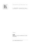
Figure 1: VS-88HD 8x8 HD-SDI Matrix Switcher
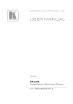
Figure 2: Connecting the VS-88HD 8x8 HD-SDI Matrix Switcher
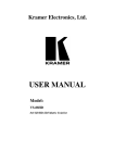
Figure 3: VS-88HD Dual-Link Inputs and Outputs
Figure 4: Connecting the Dual-Link VS-88HD 8x8 HD-SDI Matrix Switcher
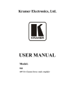
Figure 5: DIP-Switch Settings
Figure 6: Local Area Connection Properties Window
Figure 7: Internet Protocol (TCP/IP) Properties Window
Figure 8: Connect Screen
Figure 9: Device Properties Screen
Figure 10: P3K Wizard Screen
Figure 11: Connect Window
Figure 12: Device Properties Window
ii
5
10
12
12
14
17
17
18
19
25
26
27
KRAMER: SIMPLE CREATIVE TECHNOLOGY
Contents
Tables
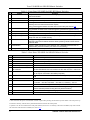
Table 1: Front Panel VS-88HD 8x8 HD-SDI Matrix Switcher
Table 2: Rear Panel VS-88HD 8x8 HD-SDI Matrix Switcher
Table 3: Machine # DIP-Switch Settings
Table 4: DIP-Switch Settings
Table 5: Genlock Settings
Table 6: VS-88HD Technical Specifications
Table 7: Communication Parameters
Table 8: VS-88HD Hex Codes for Switching via RS-232/RS-485
Table 9: Protocol Definitions
Table 10: Instruction Codes for Protocol 2000
6
6
14
14
16
24
24
35
36
37
iii
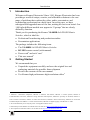
Introduction
1
Introduction
Welcome to Kramer Electronics! Since 1981, Kramer Electronics has been
providing a world of unique, creative, and affordable solutions to the vast
range of problems that confront the video, audio, presentation, and
broadcasting professional on a daily basis. In recent years, we have
redesigned and upgraded most of our line, making the best even better! Our
1,000-plus different models now appear in 13 groups1 that are clearly
defined by function.
Thank you for purchasing the Kramer VS-88HD 8x8 HD-SDI Matrix
Switcher, which is ideal for:
Professional broadcasting and production studios
Presentation applications
The package includes the following items:
The VS-88HD 8x8 HD-SDI Matrix Switcher
RC-IR3 remote control (with manual)
Power cord2 and rack “ears”
This user manual3
2
Getting Started
We recommend that you:
Unpack the equipment carefully and save the original box and
packaging materials for possible future shipment
Review the contents of this user manual
Use Kramer high performance high-resolution cables4
1 GROUP 1: Distribution Amplifiers; GROUP 2: Switchers and Routers; GROUP 3: Control Systems; GROUP 4:
Format/Standards Converters; GROUP 5: Range Extenders and Repeaters; GROUP 6: Specialty AV Products; GROUP 7:
Scan Converters and Scalers; GROUP 8: Cables and Connectors; GROUP 9: Room Connectivity; GROUP 10: Accessories
and Rack Adapters and GROUP 11: Sierra Video Products; GROUP 12: Digital Signage; and GROUP 13: Audio
2 We recommend that you use only the power cord supplied with this device
3 Download up-to-date Kramer user manuals from our Web site at http://www.kramerelectronics.com
4 The complete list of Kramer cables is on our Web site at http://www.kramerelectronics.com
1
Getting Started
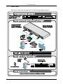
2.1
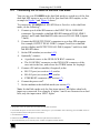
Quick Start
This quick start chart summarizes the basic setup and operation:
2
KRAMER: SIMPLE CREATIVE TECHNOLOGY
Overview
3
Overview
The VS-88HD is a high-performance matrix switcher for HD-SDI and dual
link HD-SDI signals. The unit can switch up to 8 single link inputs to any or
all of 8 single link outputs or 4 dual link inputs to any or all of 4 dual link
outputs.
In particular, the VS-88HD features:
Operation of up to 1.5Gbps – enabling it to be used for standard
definition and high-definition serial digital video signals
(SDI/HD-SDI)
SMPTE 259M, 344M, 292M, and 372M (dual link) compliance
and support for data rates of 270Mbps, 1483.5Mbps, and
1485Mbps
Cable equalization up to 350m for SD1 signals and 140m for
1.5GHz HD2 signals
Reclocking and equalization on each input, storing and recalling
setups, and a TAKE button for the execution of multiple switches
all at once
The ability to switch genlocked video signals according to the
timing of the genlock reference input. Switching according to the
bi-level or tri-level genlock3 input according to SMPTE RP-168
The VS-88HD is housed in a 19" 1U rack-mountable enclosure, and is fed
from a 100-240 VAC universal switching power supply. The unit can be
controlled via the front panel buttons or via:
An infrared remote control transmitter
An infrared remote extension cable transmitter
Remotely, by RS-232 or RS-485 serial commands transmitted by a
PC, touch screen system, or other serial controller
The Ethernet
By default, the VS-88HD is operated using the Kramer 3000
protocol (see section 7.1.9 for details of how to switch to Protocol
2000 and section 10.2 for the relevant protocol commands)
1 Standard Definition (SD) means an NTSC or PAL compatible video format, consisting of 480 (for NTSC) or 576 (for PAL)
lines of interlaced video
2 High Definition (HD) means a video format, consisting of 720 active lines of progressive video or 1080 lines of progressive
or interlaced video
3 The sources must be genlocked to the GENLOCK input in order to switch clearly
3
Your VS-88HD 8x8 HD-SDI Matrix Switcher
To achieve the best performance:
Use only good quality connection cables 1 to avoid interference,
deterioration in signal quality due to poor matching, and elevated
noise levels (often associated with low quality cables)
Avoid interference from neighboring electrical appliances that may
adversely influence signal quality and position your Kramer
VS-88HD away from moisture, excessive sunlight and dust
4
Your VS-88HD 8x8 HD-SDI Matrix Switcher
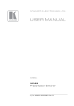
Figure 1, Table 1, and Table 2 define the VS-88HD 8x8 HD-SDI Matrix
Switcher.
1 Available from Kramer Electronics on our Web site at http://www.kramerelectronics.com
4
KRAMER: SIMPLE CREATIVE TECHNOLOGY
Your VS-88HD 8x8 HD-SDI Matrix Switcher
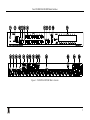
Figure 1: VS-88HD 8x8 HD-SDI Matrix Switcher
5
Your VS-88HD 8x8 HD-SDI Matrix Switcher
Table 1: Front Panel VS-88HD 8x8 HD-SDI Matrix Switcher
#
1
Feature
IR Receiver
2
3
4
POWER LED
ALL Button
OFF Button
5
IN SELECT Buttons
6
7
8
OUT SELECT Buttons
STO (STORE) Button
RCL (RECALL) Button
9
LOCK Button
10
TAKE Button
11
7-segment Display
Function
The yellow LED illuminates when receiving signals from the infrared remote
control transmitter
Illuminates when the unit is ON
Pressing ALL followed by an INPUT button, connects that input to all outputs
Pressing OFF+OUT disconnects that output from the inputs;
pressing OFF+ALL disconnects all the outputs;
a long press toggles between dual link and normal mode (see section 6.3)
Select the input to switch to the output;
long presses on buttons IN1 to IN5 change the genlock timing (see Table 5)
Select the output to which the input is switched
Pressing STO followed by an IN / OUT button stores the current setting
Pressing the RCL button and the corresponding INPUT / OUTPUT key recalls a
setup from the non-volatile memory
A long press toggles activation/inactivation of the front panel buttons;
pressing LOCK+OUT2 selects Protocol 2000; pressing LOCK+OUT3 selects
Protocol 3000
Pressing TAKE toggles the mode between the CONFIRM mode and the AT
ONCE mode (user confirmation per action is unnecessary)
Displays the selected input switched to the output (marked above each input)
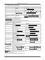
Table 2: Rear Panel VS-88HD 8x8 HD-SDI Matrix Switcher
#
12
13
14
15
16
17
18
19
20
21
22
23
24
25
Feature
GENLOCK BNC Connector
TERM HI-Z/75Ω Pushbutton
LOOP BNC Connector
INPUT BNC Connectors
RS-232 9-pin D-sub (F) Port
PROG/RS-485 TERM
DIP-switches
RS-485 Terminal Block Port
Function
Connects to the genlock source
Presstoterminatethegenlocksource(75Ω)orreleaseforlooping
Connects to the genlock connector of the next unit in the line
Connects to the serial digital video sources
Connects to the PC or the remote controller
PROG DIP-switch enables microcontroller firmware upgrade
RS-485 TERM DIP-switch terminates the RS-485linewitha120Ωload
Pins B (-) and A (+) are for RS-485;
Pin G may be connected to the shield (if required)
ETHERNET RJ-45 Connector Connects to the PC or other Serial Controller through computer networking
LAN
MACH # DIP-switches
DIP-switches 1-4 for setting the Machine Address of the unit
ETH RESET Button
Press to reset to factory default definitions1:
IP number 192.168.1.39, Mask – 255.255.0.0, Gateway – 0.0.0.0
OUTPUT BNC Connectors
Connect to the serial digital video acceptors
REMOTE IR 3.5mm Mini Jack Connect to an external IR receiver unit for controlling the machine via an IR
remote controller (instead of using the front panel IR receiver)2
Power Connector with Fuse
AC connector enabling power supply to the unit
Power Switch
Turns the power to the unit ON and OFF
1 First disconnect the power cord and then connect it again while pressing the ETH Factory Reset button. The unit powers up
and loads its memory with the factory default definitions and erases all stored presets
2 Optional. Can be used instead of the front panel (built-in) IR receiver to remotely control the VS-88HD (only if the internal
IR connection cable has been installed) (See section 4.1)
6
KRAMER: SIMPLE CREATIVE TECHNOLOGY
Your VS-88HD 8x8 HD-SDI Matrix Switcher
4.1
Using the IR Transmitter
You can use the RC-IR3 IR transmitter to control the machine via the builtin IR receiver on the front panel or, instead, via an optional external IR
receiver1. The external IR receiver can be located 15 meters away from the
machine. This distance can be extended to up to 60 meters when used with
three extension cables2.
Before using the external IR receiver, be sure to arrange for your Kramer
dealer to insert the internal IR connection cable3 with the 3.5mm connector
that fits into the REMOTE IR opening on the rear panel. Connect the
external IR receiver to the REMOTE IR 3.5mm connector.
1 Model: C-A35M/IRR-50
2 Model: C-A35M/A35F-50
3 P/N: 505-70434010-S
7
Installing the VS-88HD in a Rack
5
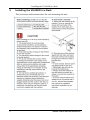
Installing the VS-88HD in a Rack
This section provides instructions for rack mounting the unit.
8
KRAMER: SIMPLE CREATIVE TECHNOLOGY
Connecting the VS-88HD
6
Connecting the VS-88HD
This section describes how to connect the VS-88HD in single link mode
(see section 6.1) and in dual link mode (see section 6.2).
6.1
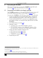
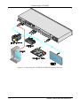
Connecting the VS-88HD in the Single Link Mode
The VS-88HD can switch one of the eight SDI/HD-SDI inputs to any or all
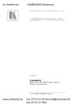
of the eight SDI/HD-SDI outputs, as the example in Figure 2 shows.
To connect the VS-88HD 8x8 HD-SDI Matrix Switcher, do the following1:
1. Connect up to eight SDI sources to the SDI INPUT BNC connectors (for
example, an HD/SD camera to INPUT 1 and an SDI player to INPUT 8).
2. Connect the SDI OUTPUT BNC connectors to up to eight SDI acceptors
(for example, OUTPUT 1 to a non-linear editor, and OUTPUT 8 to an HD
SDI display).
3. Set the DIP-switches (see section 6.4.2).
4. Optionally2, connect:
A genlock source to the GENLOCK BNC connector
The LOOP BNC connector to the GENLOCK connector of the
next unit in the line, and release the TERM button for looping3
5. Connect a PC and/or controller (if required), to the:
RS-232 port (see section 6.4), and/or
RS-485 port (see section 6.5), and/or
ETHERNET connector (see section 6.7)
6. Connect the power cord4.
1 Switch OFF the power on each device before connecting it to your VS-88HD. After connecting your VS-88HD, switch on
its power and then switch on the power on each device
2 Not illustrated in Figure 2
3 Pushed in terminates the input. Release when the input extends to another unit
4 We recommend that you use only the power cord that is supplied with this machine
9
Connecting the VS-88HD
Figure 2: Connecting the VS-88HD 8x8 HD-SDI Matrix Switcher
10
KRAMER: SIMPLE CREATIVE TECHNOLOGY
Connecting the VS-88HD
6.2
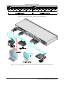
Connecting the VS-88HD in the Dual Link Mode
You can use your VS-88HD in the dual-link mode to switch any of the four
dual-link SDI inputs to any or all of the four dual-link SDI outputs, as the
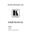
example in Figure 3 and Figure 4 shows1.
To connect the VS-88HD 8x8 HD-SDI Matrix Switcher in the dual-link
mode, do the following2:
1. Connect up to 4 of the SDI sources to the INPUT DUAL LINK BNC
connectors. For example, a dual-link HD-SDI camera to DUAL LINK 1
(inputs 1 and 2) and a dual-link HD video server to DUAL LINK 4 (inputs
7 and 8).
2. Connect the SDI OUTPUT BNC connectors to up to four SDI acceptors.
For example, OUTPUT DUAL LINK 3 (outputs 5 and 6) to a dual-link
preview display and OUTPUT DUAL LINK 4 (outputs 7 and 8) to a duallink HD-SDI mixer.
3. Set the DIP-switches (see section 6.4.2).
4. Optionally3, connect:
A genlock source to the GENLOCK BNC connector
The LOOP BNC connector to the GENLOCK connector of the
next unit in the line, and release the TERM button for looping4
5. Connect a PC and/or controller (if required), to the:
RS-232 port (see section 6.4), and/or
RS-485 port (see section 6.5), and/or
ETHERNET connector (see section 6.7)
6. Connect the power cord5.
7. Set the machine to the dual-link mode (see section 6.3).
Note: In dual link mode only the first input status LED lights when both
inputs are connected. For example, if inputs 3 and 4 are connected as a dual
link, only the input status LED 3 lights.
1 The graphic on the rear panel does not indicate the dual link connections
2 Switch OFF the power on each device before connecting it to your VS-88HD. After connecting your VS-88HD, switch on
its power and then switch on the power on each device
3 Not illustrated in Figure 2
4 Pushed in terminates the input. Release when the input extends to another unit
5 We recommend that you use only the power cord that is supplied with this machine
11
Connecting the VS-88HD
Figure 3: VS-88HD Dual-Link Inputs and Outputs
Figure 4: Connecting the Dual-Link VS-88HD 8x8 HD-SDI Matrix Switcher
12
KRAMER: SIMPLE CREATIVE TECHNOLOGY
Connecting the VS-88HD
6.3
Setting the Working Mode
To enter the dual-link mode:
Press and hold the OFF front panel button for 3 seconds until the
7-segment display shows 4 dual-link devices in the first 4 outputs
of the display and “dl” in the rest of the outputs
To exit the dual-link mode:
Press and hold the OFF front panel button for 3 seconds until the
7-segment display shows devices in all the 8 outputs
Notes:
1. The unit stays in the last working mode even after being powered down or
after rebooting. It only changes after you perform the above procedure.
2. The error sign
appears when switching to an illegal configuration. It
can also appear momentarily during switching1.
6.4
Connecting the RS-232 Port
You can connect to the VS-88HD via an RS-232 connection using, for
example, a PC. Note that a null-modem adapter/connection is not required.
To connect to the VS-88HD via RS-232:
Connect the RS-232 9-pin D-sub rear panel port on the VS-88HD
unit via a 9-wire straight cable (only pin 2 to pin 2, pin 3 to pin 3,
and pin 5 to pin 5 need to be connected) to the RS-232 9-pin D-sub
port on your PC
6.4.1 Determining the Machine Number
Each unit must be identified by a unique Machine #. Determine the
Machine # according to Table 3.
When using a single unit, set the unit to Machine # 1.
A master unit must be Machine #1.
When connecting more than one VS-88HD unit, set a different Machine #
on each unit. The units do not have to be numbered sequentially but each
unit must have a unique machine number.
1 In this case it can be ignored
13
Connecting the VS-88HD
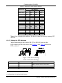
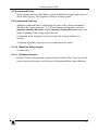
Table 3: Machine # DIP-Switch Settings
DIP-SWITCH
Machine #
1
2
3
4
1 (Single or
1
master unit )
2
OFF
ON
OFF
OFF
OFF
ON
OFF
OFF
OFF
OFF
OFF
OFF
3
ON
ON
OFF
OFF
4
OFF
OFF
ON
OFF
5
ON
OFF
ON
OFF
6
OFF
ON
ON
OFF
7
ON
ON
ON
OFF
8
OFF
OFF
OFF
ON
9
ON
OFF
OFF
ON
10
OFF
ON
OFF
ON
11
ON
ON
OFF
ON
12
OFF
OFF
ON
ON
13
ON
OFF
ON
ON
14
OFF
ON
ON
ON
15
ON
ON
ON
ON
Note: After changing the address, the device must be reset by turning OFF
and ON.
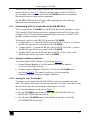
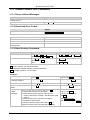
6.4.2 Setting the DIP-Switches
When controlling a unit via the RS-232 or RS-485 ports set the
DIP-switches on the rear of the unit. Figure 5 and Table 4 define the
DIP-switches2:
Figure 5: DIP-Switch Settings
Table 4: DIP-Switch Settings
DIPS
RS-485 Term
Function
RS-485 line termination
Description
OFF for no RS-485 line termination
ON for RS-485 120 line termination
PROG
Firmware update
Set ON only to update device firmware
MACH # 1, 2, 3, 4
Self Address
Sets the MACHINE #
1 A single or master unit can have the address 0 or 1
2 The default address is 0 (all DIP-switches are OFF)
14
KRAMER: SIMPLE CREATIVE TECHNOLOGY
Connecting the VS-88HD
The RS-485 TERM DIP-switch is used only when the RS-485 port is
connected (see section 6.5). The first and last units on the RS-485 line
(for example, the controller and the last VS-88HD) must be terminated;
the units in between must not be terminated.
Set the PROG DIP-switch ON only while updating the unit firmware,
otherwise the switch must be OFF.
6.5
Connecting a PC or Controller to the RS-485 Port
You can operate the VS-88HD via the RS-485 port from a distance of up to
1200 meters (3900ft) using any device equipped with an RS-485 port (for
example, a PC). For successful communication, you must set the RS-485
machine number and bus termination.
To connect a device with a RS-485 port to the VS-88HD:
Connect the A (+) pin on the RS-485 port of the PC to the A (+) pin on
the RS-485 port on the rear panel of the VS-88HD
Connect the B (–) pin on the RS-485 port of the PC to the B (–) pin on
the RS-485 port on the rear panel of the VS-88HD
Connect the G pin on the RS-485 port of the PC to the G pin on the
RS-485 port on the rear panel of the VS-88HD
6.5.1 Setting the Address Switches
To set the address DIP-switches, as shown in Figure 5:
Assign Master Machine #1 to the master unit with the address
0 or 1 set in the DIP-switches
Assign a unique Machine # from 2 to 15 for each VS-88HD slave
unit using Table 3. The units do not have to be sequentially
numbered but they must have unique addresses
6.5.2 Setting the Line Termination
To ensure correct operation, the RS-485 line must be terminated at both
ends. The master unit may be located at any part of the line, but when it is at
the end of the line, the termination switch must be set ON.
To set line termination, as shown in Figure 5:
For the VS-88HD units located at the ends of the RS-485 line, set
the RS-485 TERM DIP-switch ON
For all other VS-88HD units in the middle of the line, set the RS485 TERM DIP-switch OFF
15
Connecting the VS-88HD
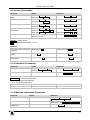
6.6
Switching Genlocked Video Signals
The genlock feature lets you switch genlocked video signals according to
timing of the GENLOCK reference input 1.
1. Connect the GENLOCK cable.
2. To set the genlock timing, press and hold for 3 seconds the appropriate input
button as follows2:
Table 5: Genlock Settings
To Set
Displayed
1080i/p @50Hz
Press and Hold
for 3 Seconds
IN 2
720p @60Hz
IN 3
720P 60H
PAL @50Hz
NTSC @60Hz
IN 4
IN 5
PAL 50H
NtSC 60H
1080 50H
Note: When turning the machine ON, the last stored setup is shown in the
7-segment display.
6.7
Connecting the Ethernet Port
You can connect the VS-88HD via the ETHERNET in the following ways:
For direct connection to the PC, use a crossover cable (see
section 6.7.1)
For connection via a network hub or network router, use a
straight-through cable (see section 6.7.2)
6.7.1 Connecting the ETHERNET Port Directly to a PC (Crossover
Cable)
You can connect the Ethernet port of the VS-88HD to the Ethernet port on
your PC, via a crossover cable with RJ-45 connectors.
This type of connection is recommended for identification of the factory default
3
IP address of the VS-88HD during the initial configuration
After connecting the Ethernet port, configure your PC as follows:
1. Right-click the My Network Places icon on your desktop.
1 According to SMPTE RP-168. The sources must be genlocked to the GENLOCK input in order to switch cleanly
2 The unit will detect automatically when SD-SDI inputs are used
3 The default IP address is 192.168.1.39
16
KRAMER: SIMPLE CREATIVE TECHNOLOGY
Connecting the VS-88HD
2. Select Properties.
3. Right-click Local Area Connection Properties.
4. Select Properties.
The Local Area Connection Properties window appears.
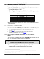
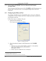
5. Select the Internet Protocol (TCP/IP) and click the Properties Button (see
Figure 6).
Figure 6: Local Area Connection Properties Window
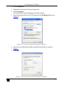
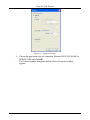
6. Select Use the following IP Address, and fill in the details as shown in
Figure 7.
7. Click OK.
Figure 7: Internet Protocol (TCP/IP) Properties Window
17
Connecting the VS-88HD
6.7.2 Connecting the ETHERNET Port via a Network Hub (StraightThrough Cable)
You can connect the Ethernet port of the VS-88HD to the Ethernet port on a
network hub or network router, via a straight-through cable with RJ-45
connectors.
6.8
Configuring the Ethernet Port
To configure the Ethernet port, download the Device Properties Ethernet
configuration software. Extract the file to a folder and create a shortcut on
your desktop to the file.
Follow these steps to configure the port:
1. Double click the desktop icon.
The Connect screen appears as follows:
Figure 8: Connect Screen
2. Select the method to connect to the Ethernet port of the VS-88HD.
Select:
Ethernet, if you know the IP address number 1 or the machine
name. The default name for the machine is
KRAMER_XXXX2
Serial, if you are connected via a serial port
1 The default IP address is 192.168.1.39
2 The four digits are the last four digits of the machine’s serial number.
18
KRAMER: SIMPLE CREATIVE TECHNOLOGY
Connecting the VS-88HD
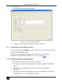
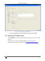
3. Click OK.
The Device Properties window appears:
Figure 9: Device Properties Screen
4. If required, make changes and press Set. If not, click Close.
6.9
Controlling via the Ethernet Port
You can control the VS-88HD via RS-232/RS-485 or the Ethernet using the
Kramer K-Router application.
If you are controlling a standalone unit via RS-232 or the Ethernet,
configure the unit as master (Mach No. 1), see section 6.4.1.
6.10 Using the Ethernet Reset Button
To reset Ethernet parameters to the factory defaults:
1. Turn the power switch OFF and then ON while pressing the ETH RESET
button.
2. The unit powers up and loads its memory with the factory default
definitions.
3. The unit also erases all stored presets, returns to the default Protocol 3000
and indicates “F-rst” on the 7-segment display.
19
Operating the VS-88HD
7
Operating the VS-88HD
You can operate your VS-88HD using:
The front panel buttons
RS-232/RS-485 serial commands transmitted by a touch screen
system, PC, or other serial controller
The RC-IR3 infrared remote control transmitter
7.1
Operating the VS-88HD from the Front Panel
The following operations are performed by using the front panel buttons.
7.1.1 Power On Display
When the VS-88HD is powered on, the display briefly shows the 4-digit
firmware version number, the genlock timing setting, and then the display
changes to its normal operating display.
7.1.2 Using the AT ONCE and CONFIRM Modes
Choose to work in either the AT ONCE or the CONFIRM modes. When the
VS-88HD operates in the AT ONCE mode, pressing an OUT-IN
combination implements the switch immediately. In the CONFIRM mode,
the change does not take place until the TAKE button is pressed.
The AT ONCE mode is faster since execution is immediate and actions
require no user confirmation. However, no protection is offered against
changing an action in error.
In the CONFIRM mode:
You can key-in several actions and then confirm them by pressing
the “TAKE” button, to simultaneously activate the multiple
switches
Every action requires user confirmation, protecting against
erroneous switching due to human error (pressing the wrong
button)
Execution is delayed until the user confirms the action
7.1.3 Switching in the AT ONCE Mode
To switch an input to an output in the AT ONCE mode, do the following:
20
KRAMER: SIMPLE CREATIVE TECHNOLOGY
Operating the VS-88HD
1. Press an OUT SELECT button1 or the ALL button.
The 7-segment display flashes.
2. Press an IN SELECT button1 or the OFF button2.
The selected input switches to the selected output. The digits displayed in
the 7-segment display change as appropriate.
7.1.4 Toggling Between Modes
To toggle between the AT ONCE and CONFIRM modes, do the following:
1. Press the TAKE button to toggle from the AT ONCE mode (in which the
TAKE button is not lit) to the CONFIRM mode (in which the TAKE button
illuminates).
Actions now require user confirmation and the TAKE button illuminates.
2. Press the illuminated TAKE button to toggle from the CONFIRM mode
back to the AT ONCE mode.
TAKE button turns off and actions no longer require user confirmation.
7.1.5 Switching in the CONFIRM Mode
To switch in the CONFIRM mode, when the TAKE button is illuminated,
do the following:
1. Press an OUT-IN combination.
The 7-segment display flashes3.
2. Press the TAKE button to confirm the action.
The 7-segment display stops flashing. The TAKE button stays lit.
To confirm several actions (in CONFIRM mode), do the following:
1. Press each OUT-IN combination in sequence.
The 7-segment display flashes.
2. Press the TAKE button to confirm all the actions.
The 7-segment display stops flashing. The TAKE button stays lit.
7.1.6 Storing an Input/Output Configuration
You can store up to 16 configurations in memory and recall them as presets
using the eight IN SELECT buttons and the eight OUT SELECT buttons.
To store the current configuration, do the following:
1 From 1 to 8
2 For immediate switching
3 The timeout lasts for 10 seconds
21
Operating the VS-88HD
1. Press the STO button.
The STO button flashes.
2. Press one of the IN / OUT SELECT buttons.
The current configuration is stored in memory at the chosen preset #.
7.1.7 Recalling an Input/Output Configuration
To recall an input/output configuration, do the following:
1. Press the RCL button.
The RCL button flashes.
2. Press the appropriate IN / OUT SELECT button (the button #
corresponding to the preset #).
The chosen preset configuration is restored from memory.
Note: Recalling an invalid setup gives an error indication.
If you cannot remember which of the eight input/output configurations is
the one that you want, set the VS-88HD to the CONFIRM mode and
manually scan all the input/output configurations until you locate it.
7.1.8 Locking the Front Panel
Lock the front panel buttons to prevent unwanted key presses from
changing the existing setup.
To lock the front panel, press and hold the LOCK key for three
seconds.
The LOCK key illuminates and the front panel keys are inactivated
To unlock the front panel, press and hold the illuminated LOCK
key until the light turns off.
The front panel keys are activated
7.1.9 Switching Protocols
You can operate the VS-88HD using either the KRAMER 2000 or the
default KRAMER 3000 serial protocol.
To choose the Kramer 2000 protocol instead of the default Protocol
3000, press LOCK and OUT 2 at the same time.
LOCK flashes briefly if the change was made correctly
To revert to the Kramer 3000 protocol, press LOCK and OUT 3 at
the same time.
LOCK flashes briefly if the change was made correctly
22
KRAMER: SIMPLE CREATIVE TECHNOLOGY
Operating the VS-88HD
7.1.10 Indicating Errors
If the front panel buttons were incorrectly pressed, such as pressing two
keys at once, or an invalid setup # was chosen for recall, the following error
indication occurs:
The STO, RCL, LOCK, and TAKE buttons all flash together for
one second and return to their previous state
If an error is indicated, retry the previous action or choose a new action.
7.2
Using Serial Commands
To operate the VS-88HD using serial commands, Kramer offers control
software that can do this. You can download free software from the Kramer
Electronics Web site.
For an explanation of all KRAMER 3000 commands, see section 10.2
For an explanation of all KRAMER 2000 commands, see section 12
7.3
Using the Infrared Remote Controller
To operate the VS-88HD using the RC-IR3 infrared remote controller, see
the User Manual packed with the remote controller 1.
Note:
The remote control cannot set single or dual mode operation or
change genlock timing. They can only be set from the front panel
The IR remote can only set 8 preset configurations equivalent to
OUT1 to OUT8
1 See also the Kramer Web site: www.kramerelectronics.com
23
Technical Specifications
8
Technical Specifications
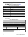
The VS-88HD technical specifications are shown in Table 6:
1
Table 6: VS-88HD Technical Specifications
INPUTS:
8 SMPTE-259M, 344M, 292M and 372M (dual link) serial video,
75ΩonBNCconnectors
8 equalized and reclocked SMPTE-259M, 344M, 292M and 372M
(dual link) outputs75ΩonBNCconnectors
OUTPUTS:
MAX. OUTPUT LEVEL:
DATA RATE:
EQUALIZATION:
800mVpp /75Ω
1.485Gbps
CONTROLS:
POWER SOURCE:
OPERATING TEMPERATURE:
STORAGE TEMPERATURE:
HUMIDITY:
DIMENSIONS:
WEIGHT:
INCLUDED ACCESSORIES:
OPTIONS:
9
Automatic equalization for losses on 75 coaxial cable
Front-panel, RS-232, RS-485, ETHERNET, remote infrared
Universal, 100-240V AC, 50/60Hz 24VA
0° to +40°C (32° to 104°F)
-40° to +70°C (-40° to 158°F)
10% to 90%, RHL non-condensing
19" x 7" x 1U W, D, H, rack mountable
2.6kg (5.7lbs) approx.
Power cord, rack“ears”andIR remote control transmitter
External remote IR receiver cable
Communication Parameters
The following table lists the communication parameters for Protocol 2000
and Protocol 3000.
Table 7: Communication Parameters
EDID
EDID data is passed between Input 1 and Output 1
RS-232
Protocol 2000
Protocol 3000 (Default)
Baud Rate:
9600
Baud Rate:
115,200
Data Bits:
8
Data Bits:
8
Stop Bits:
1
Stop Bits:
1
Parity:
None
Parity:
None
Command Format:
HEX
Command Format:
ASCII
Example (Output 1 to Input 1):
0x01, 0x81, 0x81, 0x81
Example (Output 1 to Input 1):
#AV 1>1<CR>
Switching Protocol
P2000 -> P3000
P3000 -> P2000
Command:
0x38, 0x80, 0x83, 0x81
Command:
#P2000<CR>
Front Panel:
Press LOCK and OUT 3 at the same
time
Front Panel:
Press LOCK and OUT 2 at the same
time
Ethernet
Default Settings
Reset Settings
IP Address: 192.168.1.39
Power cycle the unit while holding in the Factory Reset button,
located on the rear panel of the unit.
TCP Port #: 5000
UDP Port #: 50000
1 Specifications are subject to change without notice
24
KRAMER: SIMPLE CREATIVE TECHNOLOGY
Using the P3K Wizard
10
Using the P3K Wizard
P3K is a Kramer software program for upgrading the machine firmware and
accessing and changing device parameters. The P3K program can be
downloaded from the Kramer Web site at www.kramerelectronics.com.
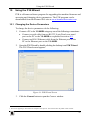
10.1 Changing the Device Parameters
To change the device parameters do the following:
1. Connect a PC to the VS-88HD using any one of the following connections:
Connect a serial cable from an RS-232 9-pin D-sub rear panel
port on the PC to the VS-88HD as explained in section 6.4.
Connect an RJ-45 Ethernet cable from the Ethernet port on the
PC to the Ethernet port on the VS-88HD.
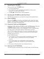
2. Open the P3K Wizard by double-clicking the desktop icon P3K Wizard.
The P3K Wizard screen appears1:
Figure 10: P3K Wizard Screen
3. Click the Connect button to open the Connect window.
1 The screens appearing in this manual are examples of the process. The actual screens may differ in their content.
25
Using the P3K Wizard
Figure 11: Connect Window
4. Choose the appropriate type of connection: Ethernet BY IP, BY NAME, or
SERIAL/USB, and click OK.
The Connect window disappears and the Device Properties window
appears.
26
KRAMER: SIMPLE CREATIVE TECHNOLOGY
Using the P3K Wizard
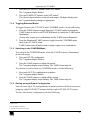
Figure 12: Device Properties Window
5. Change the parameters in the white fields as required and click SET.
10.2 Updating the VS-88HD Firmware
The VS-88HD uses a microcontroller that runs firmware located in FLASH
memory.
The latest version of firmware and installation instructions can be
downloaded from the Kramer Web site at www.kramerelectronics.com.
27
Kramer Protocol 3000
11
Kramer Protocol 3000
The VS-88HD can be operated using serial commands from a PC, remote
controller, or touch screen. The unit communicates using the default Kramer
Protocol 3000 but can also use Kramer Protocol 2000.
This section describes:
How to switch between Protocol 3000 and Protocol 2000 (see
section 11.1)
Kramer Protocol 3000 syntax (see section 11.2)
Kramer Protocol 3000 commands (see section 11.3)
11.1 Switching Protocols
Protocols can be switched either from the front panel buttons or by
transmitting protocol commands.
To switch protocols using the front panel buttons:
To choose Protocol 2000, press LOCK and OUT 2 at the same time
To choose the Protocol 3000, press LOCK and OUT 3 at the same
time
To switch protocols using protocol commands:
To switch from Protocol 3000 to Protocol 2000, send the following
command:
#P2000<CR>
To switch from Protocol 2000 to Protocol 3000, send the following
command:
0x38, 0x80, 0x83, 0x81
Note: If you are using Kramer’s Windows®-based control software1 it
operates only with Protocol 2000. If the VS-88HD is set to Protocol 3000, it
automatically switches to Protocol 2000.
1 Download the latest software from our Web site at http://www.kramerelectronics.com
28
KRAMER: SIMPLE CREATIVE TECHNOLOGY
Kramer Protocol 3000
11.2 Kramer Protocol 3000 Syntax
Protocol 3000 communicates at a data rate of 115200 baud, no parity, 8 data
bits and 1 stop bit.
11.2.1 Host Message Format
Start
#
Address (optional)
Destination_id@
Body
Message
Delimiter
CR
11.2.2 Simple Command
Command string with only one command without addressing:
Start
Body
Delimiter
#
Command SP Parameter_1,Parameter_2,…
CR
11.2.3 Command String
Formal syntax with commands concatenation and addressing:
Start
Address
Body
Delimiter
#
Destination_id@
Command_1 Parameter1_1,Parameter1_2,…|
Command_2 Parameter2_1,Parameter2_2,…|
Command_3 Parameter3_1,Parameter3_2,…|…
CR
11.2.4 Device Message Format
Start
Address (optional)
Body
delimiter
~
Sender_id@
Message
CR LF
11.2.5 Device Long Response
Echoing command:
Start
Address (optional)
Body
Delimiter
~
Sender_id@
Command SP [Param1 ,Param2 …] result
CR LF
CR = Carriage return (ASCII 13 = 0x0D)
LF = Line feed (ASCII 10 = 0x0A)
SP = Space (ASCII 32 = 0x20)
29
Kramer Protocol 3000
11.2.6 Command Terms
Command
A sequence of ASCII letters ('A'-'Z', 'a'-'z' and '-').
Command and parameters must be separated by at least one space.
Parameters
A sequence of alphameric ASCII characters ('0'-'9','A'-'Z','a'-'z' and some
special characters for specific commands). Parameters are separated by
commas.
Message string
Every command entered as part of a message string begins with a message
starting character and ends with a message closing character.
Note: A string can contain more than one command. Commands are
separated by a pipe ( '|' ) character.
Message starting character
'#' – For host command/query
'~' – For machine response
Device address (Optional, for K-NET)
K-NET Device ID followed by '@'
Query sign
'?' follows some commands to define a query request.
Message closing character
CR – For host messages; carriage return (ASCII 13)
CRLF – For machine messages; carriage return (ASCII 13) + line-feed
(ASCII 10)
Command chain separator character
When a message string contains more then one command, a pipe ( '|' )
character separates each command.
Spaces between parameters or command terms are ignored.
11.2.7 Entering Commands
You can directly enter all commands using a terminal with ASCII
communications software, such as HyperTerminal, Hercules, etc. Connect
the terminal to the serial, Ethernet, or USB port on the Kramer device. To
enter CR , press the Enter key.
( LF is also sent but is ignored by command parser).
For commands sent from some non-Kramer controllers like Crestron, some
characters require special coding (such as, /X##). Refer to the controller
manual.
30
KRAMER: SIMPLE CREATIVE TECHNOLOGY
Kramer Protocol 3000
11.2.8 Command Forms
Some commands have short name syntax in addition to long name syntax to
allow faster typing. The response is always in long syntax.
11.2.9 Command Chaining
Multiple commands can be chained in the same string. Each command is
delimited by a pipe character ( '|' ). When chaining commands, enter the
message starting character and the message closing character only once,
at the beginning of the string and at the end.
Commands in the string do not execute until the closing character is
entered.
A separate response is sent for every command in the chain.
11.2.10 Maximum String Length
64 characters
11.2.11 Backward Support
Protocol 2000 is transparently supported by Protocol 3000. You can switch
between protocols using a switch protocol command from either platform.
31
Kramer Protocol 3000
11.3 Kramer Protocol 3000 Commands
11.3.1 Device Initiated Messages
Command
Syntax
Switcher actions:
Video channel has switched (breakaway mode)
VID IN>OUT
11.3.2 Result and Error Codes
Syntax
Command ran successfully, no error.
COMMAND PARAMETERS OK
Protocol Errors:
Syntax error
ERR001
Command not available for this device
ERR002
Parameter is out of range
Unauthorized access (command run without the
matching login).
ERR003
ERR004
11.3.3 Basic Routing Commands
Command
Syntax
Response
Switch video
VID IN>OUT, IN>OUT,…
Short form: V IN>OUT, IN>OUT,…
VID IN>OUT, IN>OUT,…RESULT
Read video connection
VID? OUT
Short form: V? OUT
VID? *
VID IN>OUT
VID IN>1, IN>2,…
Parameter Description:
IN = Input number or '0' to disconnect output.
'>' = Connection character between in and out parameters.
OUT = Output number or '*' for all outputs.
Examples:
Switch video input 2 to output 4
#V 2>4CR
~VID 2>4 OKCRLF
Switch video input 4 to output 2
in machine number 6
#6@VID 4>2CR
~6@VID 4>2 OKCRLF
Disconnect video output 4
#AV 0>4CR
~AV 0>4 OKCRLF
Switch video input 3 to all
outputs
#V 3>* CR
~VID 3>* OKCRLF
Chaining
multiple
commands
32
#V 1>* | V 3>4, 2>2, 2>1, 0>2 | V 3>9 | V? * CR
1. Switch video from input 1 to all outputs.
2. Switch video input 3 to output 4, video input 2 to
output 2, video input 2 to output 1 and disconnect video
output 2.
3. Switch video input 3 to output 9 (non-existent).
4. Get status of all video links.
Command processing begins after entering CR . A
response is sent for each command after processing.
~VID 1>* OKCRLF
~VID 3>4, 2>2, 2>1, 0>2
OKCRLF
~VID ERR003 CRLF
~VID 2>1, 0>2, 1>3, 3>4 CRLF
KRAMER: SIMPLE CREATIVE TECHNOLOGY
Kramer Protocol 3000
11.3.4 Preset Commands
Command
Syntax
Response
Store current connections to
preset
PRST-STO PRESET
Short form: PSTO PRESET
PRST-STO PRESET RESULT
Recall saved preset
PRST-RCL PRESET
Short form: PRCL PRESET
PRST-RCL PRESET RESULT
Delete saved preset
PRST-DEL PRESET
Short form: PDEL PRESET
PRST-DEL PRESET RESULT
Read video connections from
saved preset
PRST-VID? PRESET,OUT
Short form: PVID? PRESET,OUT
PRST-VID? PRESET, *
PRST-VID PRESET, IN>OUT
Read saved presets list
PRST-LST?
Short form: PLST?
PRST-LST PRESET, PRESET,…
PRST-VID PRESET, IN>1, IN>2,…
Parameter Description:
PRESET = Preset number.
OUT = Output in preset to display, '*' for all.
Examples:
Store current video connections #PRST-STO 5CR
to preset 5
~PRST-STR 5 OKCRLF
Recall video connections from
preset 3
#PRCL 3CR
~PRST-RCL 3 OKCRLF
Show source of video output 2
from preset 3
#PRST-VID? 3,2CR
~PRST-VID 3: 4>2 CRLF
11.3.5 Operation Commands
Command
Syntax
Response
Lock front panel
LOCK-FP LOCK-MODE
Short form: LCK LOCK-MODE
LOCK-FP LOCK-MODE RESULT
Get front panel locking state
LOCK-FP?
LOCK-FP LOCK-MODE
Parameter Description:
LOCK-MODE = Front panel locking state:
‘0’or‘off’tounlockfront panel buttons
‘1’or‘on’tolockfrontpanelbuttons
Reset device
RESET
RESET OK
Switch to protocol 2000*
P2000 OK
P2000
* Protocol 2000 has a command to switch back to ASCII protocol (like Protocol 3000)
11.3.6 Machine Information Commands
Command
Syntax
Response
Read in/out count
INFO-IO?
INFO-IO: IN INPUTS_COUNT, OUT
OUTPUTS_COUNT
Read max preset count
INFO-PRST?
INFO-PRST: VID PRESET_VIDEO_COUNT
Reset to factory default
configuration
FACTORY
FACTORY RESULT
33
Kramer Protocol 3000
11.3.7 Identification Commands
Command
Syntax
Response
Protocol handshaking
#CR
~OK CRLF
Read device model
MODEL?
MODEL MACHINE_MODEL
Read device serial number
SN?
SN SERIAL_NUMBER
Read device firmware version
VERSION?
VERSION MAJOR .MINOR .BUILD .REVISION
Set machine name
NAME
MACHINE_NAME
NAME MACHINE_NAME RESULT
Read machine name
NAME?
NAME MACHINE_NAME
Reset machine name to factory
default*
NAME-RST
NAME-RST MACHINE_FACTORY_NAME
RESULT
*Note: The machine name is not the same as the model name. The machine name is used to identify a specific
machine or a network in use (with DNS feature on).
MACHINE_NAME = Up to 14 alphameric chars.
* Machine factory name = Model name + last 4 digits from serial number.
11.3.8 Network Setting Commands
Command
Syntax
Response
Set IP address
NET-IP IP_ADDRESS
Short form: NTIP
NET-IP IP_ADDRESS RESULT
Read IP address
NET-IP?
Short form: NTIP?
NET-MAC?
Short form: NTMC?
NET-IP IP_ADDRESS
NET-MASK SUBNET_MASK
Short form: NTMSK
NET-MASK?
Short form: NTMSK?
NET-MASK SUBNET_MASK RESULT
Set gateway address
NET-GATE GATEWAY_ADDRESS
Short form: NTGT
NET-GATE GATEWAY_ADDRESS
RESULT
Read subnet mask
NET-GATE?
Short form: NTGT?
NET-GATE GATEWAY_ADDRESS
Set DHCP mode
NET-DHCP DHCP_MODE
Short form: NTDH
NET-DHCP?
Short form: NTDH?
NET-DHCP DHCP_MODE RESULT
Read MAC address
Set subnet mask
Read subnet mask
Read subnet mask
NET-MAC MAC_ADDRESS
NET-MASK SUBNET_MASK
NET-DHCP DHCP_MODE
DHCP_MODE =
‘0’– Don't use DHCP (Use IP set by factory or IP set command).
‘1’– Try to use DHCP, if unavailable use IP as above.
Change protocol
Ethernet port
ETH-PORT PROTOCOL , PORT
Short form: ETHP
ETH-PORT PROTOCOL ,PORT RESULT
Read protocol
Ethernet port
ETH-PORT? PROTOCOL
Short form: ETHP?
ETH-PORT PROTOCOL , PORT
PROTOCOL = TCP/UDP (transport layer protocol)
PORT = Ethernet port that accepts Protocol 3000 commands
1-65535 = User defined port
0 - Reset port to factory default (50000 for UDP, 5000 for TCP)
34
KRAMER: SIMPLE CREATIVE TECHNOLOGY
Hex Table (Protocol 2000)
12
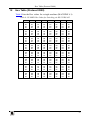
Hex Table (Protocol 2000)
Table 8 lists the Hex values for a single machine (MACHINE # 1):
Table 8: VS-88HD Hex Codes for Switching via RS-232/RS-485
IN 1
IN 2
IN 3
IN 4
IN 5
IN 6
IN 7
IN 8
OUT 1
10
10
10
10
10
18
10
10
10
18
10
10
10
18
10
10
10
18
10
10
10
18
10
10
10
18
10
10
10
11
10
10
OUT 2
10
10
18
10
10
18
18
10
10
18
18
10
10
18
18
10
10
18
18
10
10
18
18
10
10
18
18
10
10
11
18
10
OUT 3
10
10
18
10
10
18
18
10
10
18
18
10
10
18
18
10
10
18
18
10
10
18
18
10
10
18
18
10
10
11
18
10
OUT 4
10
10
18
10
10
18
18
10
10
18
18
10
10
18
18
10
10
18
18
10
10
18
18
10
10
18
18
10
10
11
18
10
OUT 5
10
10
18
10
10
18
18
10
10
18
18
10
10
18
18
10
10
18
18
10
10
18
18
10
10
18
18
10
10
11
18
10
OUT 6
10
10
18
10
10
18
18
10
10
18
18
10
10
18
18
10
10
18
18
10
10
18
18
10
10
18
18
10
10
11
18
10
OUT 7
10
10
18
10
10
18
18
10
10
18
18
10
10
18
18
10
10
18
18
10
10
18
18
10
10
18
18
10
10
11
18
10
OUT 8
10
10
11
10
10
18
11
10
10
18
11
10
10
18
11
10
10
18
11
10
10
18
11
10
10
18
11
10
10
11
11
10
35
Kramer Protocol 2000
13
Kramer Protocol 2000
The VS-88HD is compatible with Kramer’s Protocol 20001, version 0.50.
This RS-232/RS-485 communication protocol uses four bytes of
information as defined below. The default data rate is 9600 baud, with no
parity, 8 data bits, and 1 stop bit.
Table 9: Protocol Definitions
MSB
LSB
DESTINATION
0
7
INSTRUCTION
D
6
N5
5
N4
4
N3
3
1
7
I6
6
I5
5
I4
4
I3
3
1
7
O6
6
O5
5
O4
4
O3
3
OVR
6
X
5
M4
4
M3
3
N2
2
N1
1
N0
0
I2
2
I1
1
I0
0
O2
2
O1
1
O0
0
1st byte
INPUT
2nd byte
OUTPUT
3rd byte
MACHINE NUMBER
1
7
4th byte
M2
2
M1
1
M0
0
1st BYTE:
Bit 7 – Defined as 0.
D – “DESTINATION”:
0 - for sending information to the switchers (from the PC);
1 - for sending to the PC (from the switcher).
N5…N0 – “INSTRUCTION”
The function that is to be performed by the switcher(s) is defined by the INSTRUCTION (6 bits). Similarly, if a function is
performed via the machine’s keyboard, then these bits are set with the INSTRUCTION NO., which was performed. The
instruction codes are defined according to the table below (INSTRUCTION NO. is the value to be set for N5…N0).
2nd BYTE:
Bit 7 – Defined as 1.
I6…I0 – “INPUT”.
When switching (i.e. instruction codes 1 and 2), the INPUT (7 bits) is set as the input number which is to be switched.
Similarly, if switching is done via the machine’s front-panel, then these bits are set with the INPUT NUMBER which was
switched. For other operations, these bits are defined according to the table.
3rd BYTE:
Bit 7 – Defined as 1.
O6…O0 – “OUTPUT”.
When switching (i.e. instruction codes 1 and 2), the OUTPUT (7 bits) is set as the output number which is to be switched.
Similarly, if switching is done via the machine’s front-panel, then these bits are set with the OUTPUT NUMBER which was
switched. For other operations, these bits are defined according to the table.
4th BYTE:
Bit 7 – Defined as 1.
Bit 5 – Don’t care.
OVR – Machine number override.
M4…M0 – MACHINE NUMBER.
Used to address machines in a system via their machine numbers. When several machines are controlled from a single serial
port, they are usually configured together with each machine having an individual machine number. If the OVR bit is set, then
all machine numbers will accept (implement) the command, and the addressed machine will reply.
1 You can download our user-friendly “Software for Calculating Hex Codes for Protocol 2000” from the technical support
section on our Web site at: http://www.kramerelectronics.com
36
KRAMER: SIMPLE CREATIVE TECHNOLOGY
Kramer Protocol 2000
For a single machine controlled via the serial port, always set M4…M0 = 1, and make sure that the machine itself is
configured as MACHINE NUMBER = 1.
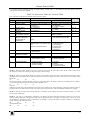
Table 10: Instruction Codes for Protocol 2000
Note: All values in the table are decimal, unless otherwise stated.
#
INSTRUCTION
DESCRIPTION
0
1
RESET DEVICE
SWITCH VIDEO
3
16
STORE VIDEO
STATUS
RECALL VIDEO
STATUS
REQUEST STATUS
OF A VIDEO OUTPUT
REQUEST WHETHER
SETUP IS DEFINED /
VALID INPUT IS
DETECTED
ERROR / BUSY
30
LOCK FRONT PANEL
31
56
61
REQUEST WHETHER
PANEL IS LOCKED
CHANGE TO ASCII
IDENTIFY MACHINE
62
DEFINE MACHINE
4
5
15
NOTES on the above table:
DEFINITION FOR SPECIFIC INSTRUCTION
INPUT
OUTPUT
0
Set equal to video input which is to
be switched
(0 = disconnect)
Set as SETUP #
Set as SETUP #
Set as SETUP #
SETUP #
or
Input #
For invalid / valid input (i.e.
OUTPUT byte = 4 or OUTPUT byte
= 5),
this byte is set as the input #
0 - Panel unlocked
1 - Panel locked
0
0
Set equal to video output which is
to be switched
(0 = to all the outputs)
0 - to store
1 - to delete
0
NOTE
1
2, 15
2, 3, 15
2, 3, 15
Equal to output number whose
4, 3
status is required
0 - for checking if setup is defined 8
1 - for checking if input is valid
0 - error
1 - invalid instruction
2 - out of range
3 - machine busy
4 - invalid input
5 - valid input
0
9, 25
2
0
16
0
1 - video machine name
3 - video software version
3 – Protocol 3000l
0 - Request first 4 digits
1 - Request first suffix
19
13
1 - number of inputs
2 - number of outputs
3 - number of setups
1 - for video
3 - for SDI
4 - for remote panel
5 - for RS-422 controller
14
NOTE 1 - When the master switcher is reset, (e.g. when it is turned on), the reset code is sent to the PC. If this code is sent to
the switchers, it will reset according to the present power-down settings.
NOTE 2 - These are bi-directional definitions. That is, if the switcher receives the code, it will perform the instruction; and if
the instruction is performed (due to a keystroke operation on the front panel), then these codes are sent. For example, if the
HEX code
01
85
88
83
was sent from the PC, then the switcher (machine 3) will switch input 5 to output 8. If the user switched input 1 to output 7
via the front panel keypad, then the switcher will send HEX codes:
41
81
87
83
to the PC.
When the PC sends one of the commands in this group to the switcher, then, if the instruction is valid, the switcher replies by
sending to the PC the same four bytes that it was sent (except for the first byte, where the DESTINATION bit is set high).
NOTE 3 - SETUP # 0 is the present setting. SETUP # 1 and higher are the settings saved in the switcher's memory, (i.e. those
used for Store and Recall).
NOTE 4 - The reply to a "REQUEST" instruction is as follows: the same instruction and INPUT codes as were sent are
returned, and the OUTPUT is assigned the value of the requested parameter. The replies to instructions 10 and 11 are as per
the definitions in instructions 7 and 8 respectively. For example, if the present status of machine number 5 is breakaway
setting, then the reply to the HEX code
0B
80
80
85
would be HEX codes
4B
80
81
85
37
Kramer Protocol 2000
NOTE 8 - The reply is as in TYPE 3 above, except that here the OUTPUT is assigned with the value 0 if the setup is not
defined / no valid input is detected; or 1 if it is defined / valid input is detected.
NOTE 9 - An error code is returned to the PC if an invalid instruction code was sent to the switcher, or if a parameter
associated with the instruction is out of range (e.g. trying to save to a setup greater than the highest one, or trying to switch an
input or output greater than the highest one defined). This code is also returned to the PC if an RS-232 instruction is sent
while the machine is being programmed via the front panel. Reception of this code by the switcher is not valid.
NOTE 13 - This is a request to identify the switcher/s in the system. If the OUTPUT is set as 0, and the INPUT is set as 1, 2,
5 or 7, the machine will send its name. The reply is the decimal value of the INPUT and OUTPUT. For example, for a 2216,
the reply to the request to send the machine name would be (HEX codes):
7D
96
90
81 (i.e. 128dec+ 22dec for 2nd byte, and 128dec+ 16dec for 3rd byte).
If the request for identification is sent with the INPUT set as 3 or 4, the appropriate machine will send its software version
number. Again, the reply would be the decimal value of the INPUT and OUTPUT - the INPUT representing the number in
front of the decimal point, and the OUTPUT representing the number after it. For example, for version 3.5, the reply to the
request to send the version number would be (HEX codes):
7D
83
85
81 (i.e. 128dec+ 3dec for 2nd byte, 128dec+ 5dec for 3rd byte).
If the OUTPUT is set as 1, then the ASCII coding of the lettering following the machine’s name is sent. For example, for the
VS-7588YC, the reply to the request to send the first suffix would be (HEX codes):
7D
D9
C3
81 (i.e. 128dec+ ASCII for “Y”; 128dec+ ASCII for “C”).
NOTE 14 - The number of inputs and outputs refers to the specific machine which is being addressed, not to the system. For
example, if six 16X16 matrices are configured to make a 48X32 system (48 inputs, 32 outputs), the reply to the HEX code
3E
82
81
82 (i.e. request the number of outputs)
would be HEX codes
7E
82
90
82
i.e. 16 outputs
NOTE 15 – When the OVR bit (4th byte) is set, then the “video” commands have universal meaning. For example, instruction
1 (SWITCH VIDEO) will cause all units (including data, etc.) to switch. Similarly, if a machine is in “FOLLOW” mode, it
will perform any “video” instruction.
NOTE 16 - The reply to the “REQUEST WHETHER PANEL IS LOCKED” is as in NOTE 4 above, except that here the
OUTPUT is assigned with the value 0 if the panel is unlocked, or 1 if it is locked.
NOTE 19 – After this instruction is sent, the unit will respond to the ASCII command set defined by the OUTPUT byte. The
ASCII command to operate with the HEX command set must be sent in order to return to working with HEX codes.
NOTE 25 – For units which detect the validity of the video inputs, Instruction 16 will be sent whenever the unit detects a
change in the state of an input (in real-time).
For example, if input 3 is detected as invalid, the unit will send the HEX codes
10
83
84
81
If input 7 is detected as valid, then the unit will send HEX codes
10
87
85
81.
38
KRAMER: SIMPLE CREATIVE TECHNOLOGY
39
For the latest information on our products and a list of Kramer
distributors, visit our Web site: www.kramerelectronics.com
where updates to this user manual may be found.
We welcome your questions, comments and feedback.
Safety Warning:
Disconnect the unit from the power supply before
opening/servicing.
Caution
P/N: 2900- 000631
Rev:
2A
Kramer Electronics, Ltd.
Web site: www.kramerelectronics.com
E-mail: [email protected]
P/N: 2900-000631 REV 2A