1
Kramer Electronics, Ltd.
USER MANUAL
Model:
VS-88DTP
8x8 DVI - Twisted Pair Matrix Switcher
Contents
Contents
1
2
2.1
3
3.1
3.2
4
4.1
5
6
6.1
6.2
Introduction
Getting Started
Quick Start
Overview
Recommendations for Best Performance
Using Twisted Pair Cable
Defining the VS-88DTP 8x8 DVI - Twisted Pair Matrix Switcher
Using the IR Transmitter
Installing the VS-88DTP in a Rack
Connecting the VS-88DTP 8x8 DVI - Twisted Pair Matrix Switcher
Connecting to the VS-88DTP via RS-232
Connecting to the VS-88DTP via RS-485
1
1
2
3
3
4
5
7
8
9
10
10
6.3
Connecting to the VS-88DTP via Ethernet
13
7
7.1
7.2
7.3
7.4
7.5
Operating the VS-88DTP 8x8 DVI - Twisted Pair Matrix Switcher
Routing Inputs to Outputs
Disconnecting Outputs
Storing and Recalling Setups in Presets
Switching between Protocol 2000 and Protocol 3000
Acquiring the EDID
14
14
14
15
15
16
7.6
7.7
8
8.1
8.2
Locking and Unlocking the Front Panel Buttons
Control Configuration via the Ethernet Port
Controlling the VS-88DTP Remotely via Ethernet
Connecting to the VS-88DTP via your Browser
The Main Switching Matrix Page
17
17
17
18
20
8.3
9
The Configuration Page
Technical Specifications
24
25
6.2.1
6.2.2
6.2.3
6.3.1
6.3.2
7.5.1
7.5.2
7.5.3
8.2.1
8.2.2
8.2.3
8.2.4
Setting the RS-485 Machine Number
Setting the RS-485 Bus Termination
Connecting and Controlling Multiple VS-88DTP Devices
Connecting to the Ethernet Port directly to a PC
Connecting to the Ethernet Port via a Network Hub
Acquiring an EDID from a Single Output
Acquiring an EDID from Several Outputs to Several Inputs
Acquiring the Default EDID
Switching an Input to an Output
Operating in the Offline Mode
Storing and Recalling Setups
Locking the Front Panel Buttons
10
11
12
13
14
16
16
17
20
21
22
24
i
Contents
10
11
12
13
14
15
15.1
Default Communication Parameters
Default EDID
Updating the VS-88DTP Firmware
Table of ASCII Codes for Serial Communication (Protocol 3000)
Hex Codes for Serial Communication (Protocol 2000)
Kramer Protocol
Switching Protocols
25
26
27
27
28
28
28
15.2
Kramer Protocol 3000
29
15.3
Kramer Protocol 2000
35
15.1.1 Switching Protocols via the Front Panel Buttons
15.2.1 Host Message Format
15.2.1.1 Simple Command
15.2.1.2 Command String
15.2.2 Device Message Format
15.2.2.1 Device Long Response
15.2.3 Command Terms
15.2.4 Entering Commands
15.2.5 Command Forms
15.2.6 Command Chaining
15.2.7 Maximum String Length
15.2.8 Backward Support
28
29
29
29
29
29
29
30
30
31
31
31
Figures
Figure 1: VS-88DTP 8x8 DVI - Twisted Pair Matrix Switcher Front View
Figure 2: VS-88DTP 8x8 DVI - Twisted Pair Matrix Switcher Rear View
Figure 3: Connecting the VS-88DTP 8x8 DVI - Twisted Pair Matrix Switcher
Figure 4: RS-485 DIP-switches
Figure 5: RS-485 Termination DIP-switch
Figure 6: Control of Multiple VS-88DTP Devices via RS-232 and RS-485
Figure 7: Local Area Connection Properties Window
Figure 8: Internet Protocol (TCP/IP) Properties Window
Figure 9: Preset Number Assignments using the Selector Buttons
Figure 10: Java Test Page Success Message
Figure 11: Entering the IP Number in the Address Bar
Figure 12: The Loading Page
Figure 13: First Time Security Warning
Figure 14: Main Switching Matrix Page
Figure 15: Selecting a Switching Point on the Matrix
Figure 16: Switching in the Offline Mode
Figure 17: Selecting Preset 07
Figure 18: Selecting Preset 03
Figure 19: Recalling a Preset in Offline Mode
Figure 20: Configuration Page
ii
5
6
9
11
11
12
13
14
15
18
18
19
19
20
21
21
22
23
23
24
KRAMER: SIMPLE CREATIVE TECHNOLOGY
Contents
Tables
Table 1: VS-88DTP 8x8 DVI - Twisted Pair Matrix Switcher Front Panel Features
Table 2: VS-88DTP 8x8 DVI - Twisted Pair Matrix Switcher Rear Panel Features
Table 3: Machine Number DIP-switch Settings
Table 4: VS-88DTP Technical Specifications
Table 5: Default Communication Parameters
Table 6: VS-88DTP Video Signal Codes for Protocol 3000
Table 7: VS-88DTP Hex Codes for Switching via RS-232/RS-485
Table 8: Instruction Codes for Protocol 3000
Table 9: Protocol Definitions
Table 10: Instruction Codes for Protocol 2000
5
6
11
25
25
27
28
31
35
36
iii
Introduction
1
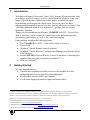
Introduction
Welcome to Kramer Electronics! Since 1981, Kramer Electronics has been
providing a world of unique, creative, and affordable solutions to the vast
range of problems that confront the video, audio, presentation, and
broadcasting professional on a daily basis. In recent years, we have
redesigned and upgraded most of our line, making the best even better! Our
1,000-plus different models now appear in 11 groups 1 that are clearly
defined by function.
Thank you for purchasing the Kramer VS-88DTP 8x8 DVI - Twisted Pair
Matrix Switcher, which is ideal for conference room presentations and
advertising applications, as well as for rental and staging.
Each package includes the following items:
• The VS-88DTP 8x8 DVI - Twisted Pair Matrix Switcher
• Power cord 2
• Windows®-based Kramer control software 3
• Windows®-based Ethernet Configuration Manager and Virtual Serial
Port Manager
• Kramer RC-IR3 Infrared Remote Control Transmitter (including the
required batteries and a separate user manual 4)
• This user manual4
2
Getting Started
We recommend that you:
• Unpack the equipment carefully and save the original box and
packaging materials for possible future shipment
• Review the contents of this user manual
• Use Kramer high-performance high resolution cables 5
1 GROUP 1: Distribution Amplifiers; GROUP 2: Switchers and Matrix Switchers; GROUP 3: Control Systems;
GROUP 4: Format/Standards Converters; GROUP 5: Range Extenders and Repeaters; GROUP 6: Specialty AV Products;
GROUP 7: Scan Converters and Scalers; GROUP 8: Cables and Connectors; GROUP 9: Room Connectivity;
GROUP 10: Accessories and Rack Adapters; GROUP 11: Sierra Products
2 We recommend that you use only the power cord supplied with this device
3 Downloadable from http://www.kramerelectronics.com
4 Download up-to-date Kramer user manuals from http://www.kramerelectronics.com
5 The complete list of Kramer cables is on http://www.kramerelectronics.com
1
Getting Started
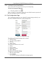
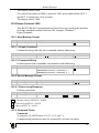
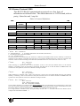
2.1 Quick Start
This quick start chart summarizes the basic setup and operation steps.
2
KRAMER: SIMPLE CREATIVE TECHNOLOGY
Overview
3
Overview
The high quality Kramer VS-88DTP is an 8x8 DVI - Twisted Pair Matrix
Switcher that accepts up to eight DVI inputs and routes any or all of them to
any or all eight TP (Twisted Pair) outputs for connection to compatible TP
receivers, for example, the PT-572HDCP+ or TP-574.
The VS-88DTP features:
• I-EDIDPro™ Kramer Intelligent EDID Processing™, an intelligent
EDID handling and processing algorithm that ensures Plug and Play
operation for DVI systems
• An OFF button to disconnect one or all outputs
• A LOCK button to prevent unwanted tampering with the front panel
buttons
• 16 preset memory locations for storing configuration configurations
• 1U height that fits a standard 19” professional rack enclosure
You can control the VS-88DTP using the front panel buttons, or remotely
via:
• RS-232/RS-485 serial commands transmitted by a touch screen
system, PC or other serial controller
• The Kramer infrared remote control transmitter
• Ethernet over a LAN
• An external remote IR receiver (optional, see Section 4.1)
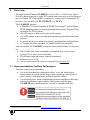
3.1 Recommendations for Best Performance
To achieve the best performance:
• Use only high-quality connection cables 1 to avoid interference,
deterioration in signal quality due to poor matching, and elevated
noise levels (often associated with low quality cables).
• Avoid interference from neighboring electrical appliances that may
adversely influence signal quality and position your Kramer
VS-88DTP away from moisture, excessive sunlight, and dust
1 Available from Kramer Electronics on our Web site at http://www.kramerelectronics.com
3
Overview
3.2 Using Twisted Pair Cable
Kramer engineers have developed special twisted pair cables to best match
our digital twisted pair products; the Kramer BC-DGKat524 (CAT 5
24 AWG), the Kramer BC-DGKat623 (CAT 6 23 AWG cable), and the
Kramer BC-DGKat7a23 (CAT 7a 23 AWG cable). These specially built
cables significantly outperform regular CAT 5/CAT 6/CAT 7a cables.
4
KRAMER: SIMPLE CREATIVE TECHNOLOGY
Defining the VS-88DTP 8x8 DVI - Twisted Pair Matrix Switcher
4
Defining the VS-88DTP 8x8 DVI - Twisted Pair Matrix Switcher
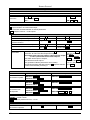
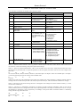
Figure 1 and Table 1 define the front view of the VS-88DTP.
Figure 1: VS-88DTP 8x8 DVI - Twisted Pair Matrix Switcher Front View
Table 1: VS-88DTP 8x8 DVI - Twisted Pair Matrix Switcher Front Panel Features
#
1
2
3
4
5
6
7
8
9
10
11
12
13
Feature
IR LED
IR Sensor
POWER LED
ALL Button
OFF Button
SELECT IN Buttons
SELECT OUT Buttons
STO Button
RCL Button
LOCK Button
EDID Button 1
OUTPUT Numbers
7-segment Display
Function
Lights yellow when receiving a signal from an IR remote control
IR remote control signal receiver
Lights green when the device is powered on
Press to select all outputs (see Section 7.1)
Press to disconnect one or all outputs (see Section 7.2)
Press to select an input (1 to 8) following the selection of an output
Press to select an output (1 to 8) followed by the selection of an input
Press to store a matrix configuration
Press to recall a matrix configuration
Press and hold to toggle locking and unlocking the front panel buttons (see Section 8.2.4)
Press to acquire the EDID (see Section 7.5)
Indicates the relevant output to which an input (1 to 8, shown on the 7-segment display) is currently switched
Displays the selected video input switched to the output (marked above each input)
1 Lights when configuring the EDID
5
Defining the VS-88DTP 8x8 DVI - Twisted Pair Matrix Switcher
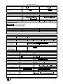
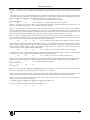
Figure 2 and Table 2 define the front view of the VS-88DTP.
Figure 2: VS-88DTP 8x8 DVI - Twisted Pair Matrix Switcher Rear View
Table 2: VS-88DTP 8x8 DVI - Twisted Pair Matrix Switcher Rear Panel Features
1
2
3
4
6
#
Feature
IN 1 to IN 8 DVI Input Connectors
OUT 1 to OUT 8 RJ-45 TP Output Connectors
RS-232 9-pin D-sub (F)
PROG TERM 2-way DIP-switch
5
RS-485 3-pin Terminal Block
6
7
ETHERNET RJ-45 TP Connector
REMOTE IR 3.5mm Mini Jack
8
9
MACH # DIP-Switch
RESET Button
10
11
12
AC Power Receptacle
AC Mains Fuse
AC Mains Power Switch
Function
Connect to the DVI sources
Connect to the TP receivers (for example, PT-572HDCP+ and TP-574)
Connect to a PC or other serial remote controller
DIP-switch 1
DIP-switch 2
Sets the RS-485 bus termination (see Section 6.2.2) Sets the Programming mode. Only for the use of
Kramer service personnel. Default = Off
Up = Off, Down = On. Default = On
Connect to a serial controller or to another VS-88DTP unit.
Connect G to Ground, B to B, and A to A (see Section 6.2)
Connect to a PC or LAN for remote control
Connect to an external IR receiver unit for controlling the device via an IR remote controller (instead of using
the front panel IR receiver)
Sets the RS-485 bus machine number (see Section 6.2.1)
Press the reset button while turning the device on in order to reset the Ethernet factory default definitions
(see Section 10)
Connect to the AC mains power supply
AC mains supply protection fuse
Turns the AC mains power supply to the device on and off
KRAMER: SIMPLE CREATIVE TECHNOLOGY
Defining the VS-88DTP 8x8 DVI - Twisted Pair Matrix Switcher
4.1 Using the IR Transmitter
You can use the RC-IR3 IR transmitter to control the device via the built-in
IR receiver on the front panel or, instead, via an optional external IR
receiver 1. The external IR receiver can be located up to 15m (48ft) away
from the device. This distance can be extended to up to 60m (197ft) when
used with three extension cables 2
Before using the external IR receiver, be sure to arrange for your Kramer
dealer to insert the internal IR connection cable 3 with the 3.5mm mini jack
that fits into the REMOTE IR opening on the rear panel. Connect the
external IR receiver to the REMOTE IR 3.5mm mini jack.
9F
1 Model: C-A35M/IRR-50
2 Model: C-A35M/A35F-50
3 P/N: 505-70434010-S
7
Installing the VS-88DTP in a Rack
5
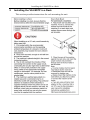
Installing the VS-88DTP in a Rack
This section provides instructions for rack mounting the unit.
.
8
KRAMER: SIMPLE CREATIVE TECHNOLOGY
Connecting the VS-88DTP 8x8 DVI - Twisted Pair Matrix Switcher
6
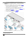
Connecting the VS-88DTP 8x8 DVI - Twisted Pair Matrix
Switcher
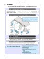
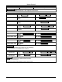
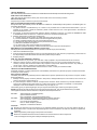
To connect the VS-88DTP as illustrated in the example in Figure 3:
1. Connect up to eight DVI sources 1 (for example, computer graphics
sources) to the IN 1 to IN 8 DVI connectors.
2. Connect the OUT 1 to OUT 8 TP connectors to up to eight 2 TP
receivers (for example, the PT-572HDCP+ and TP-574).
3. If required, connect a controller to the RS-232 (see Section 6.1) and/or
Ethernet port (see Section 6.3).
4. Connect the power cord (not shown in Figure 3).
5. If required, acquire the EDID (see Section 7.5).
Figure 3: Connecting the VS-88DTP 8x8 DVI - Twisted Pair Matrix Switcher
1 You do not have to connect all the sources
2 You do not have to connect all outputs
9
Connecting the VS-88DTP 8x8 DVI - Twisted Pair Matrix Switcher
6.1 Connecting to the VS-88DTP via RS-232
You can connect to the VS-88DTP via an RS-232 connection using, for
example, a PC. Note that a null-modem adapter/connection is not required.
To connect to the VS-88DTP via RS-232:
• Connect the RS-232 9-pin D-sub rear panel port on the
VS-88DTP unit via a 9-wire straight cable (only pin 2 to pin 2, pin 3
to pin 3, and pin 5 to pin 5 need to be connected) to the RS-232 9-pin
D-sub port on your PC
6.2 Connecting to the VS-88DTP via RS-485
You can operate the VS-88DTP via the RS-485 port from a distance of up
to 1200m (3900ft) using any device equipped with an RS-485 port (for
example, a PC). For successful communication, you must set the RS-485
machine number and bus termination.
To connect a device with a RS-485 port to the VS-88DTP:
1. Connect the TxD+ pin on the RS-485 port of the PC to the A pin on
the RS-485 port on the rear panel of the VS-88DTP.
2. Connect the TxD– pin on the RS-485 port of the PC to the B pin on the
RS-485 port on the rear panel of the VS-88DTP.
3. If shielded TP cable is used, the shield may be connected to the G
(ground) pin on the unit.
6.2.1 Setting the RS-485 Machine Number
When several VS-88DTP units are connected, the machine number
determines the unique identity of the VS-88DTP on the bus (see Table 3).
Note:
• When using a stand-alone VS-88DTP unit, set the machine number
to 1 (factory default)
• When connecting more than one VS-88DTP, set the first machine
(connected via RS-232) to be machine number 1. The other
VS-88DTP units must each be set to a unique machine number
between 2 and 16
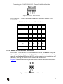
The machine number on the VS-88DTP is set using the DIP-switches on the
rear panel.
To set the RS-485 machine number using the DIP-switches:
Figure 4 illustrates the factory default MACH # DIP-switch settings.
10
KRAMER: SIMPLE CREATIVE TECHNOLOGY
Connecting the VS-88DTP 8x8 DVI - Twisted Pair Matrix Switcher
Figure 4: RS-485 DIP-switches
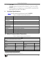
DIP-switches 1, 2 and 3 determine the RS-485 machine number of the
VS-88DTP.
Table 3: Machine Number DIP-switch Settings
Machine Number
1
2
3
4
1 (Default)
OFF
OFF
OFF
OFF
2
OFF
OFF
OFF
ON
3
OFF
OFF
ON
OFF
4
OFF
OFF
ON
ON
5
OFF
ON
OFF
OFF
6
OFF
ON
OFF
ON
7
OFF
ON
ON
OFF
8
OFF
ON
ON
ON
OFF
9
ON
OFF
OFF
10
ON
OFF
OFF
ON
11
ON
OFF
ON
OFF
12
ON
OFF
ON
ON
13
ON
ON
OFF
OFF
14
ON
ON
OFF
ON
15
ON
ON
ON
OFF
16
ON
ON
ON
ON
6.2.2 Setting the RS-485 Bus Termination
DIP-switch 1 sets the RS-485 bus termination of the VS-88DTP. Only the
first and last physical units on the RS-485 bus must be terminated, all others
must be unterminated. Moving the DIP-switch up turns the termination off
(default), moving the switch down enables the termination.
Figure 5 illustrates the factory default PROG TERM DIP-switch positions.
Figure 5: RS-485 Termination DIP-switch
11
Connecting the VS-88DTP 8x8 DVI - Twisted Pair Matrix Switcher
6.2.3 Connecting and Controlling Multiple VS-88DTP Devices
You can daisy-chain up to 16 VS-88DTP devices with operation via
RS-232 from a PC or serial controller (see Figure 6).
To daisy-chain up to 16 VS-88DTP devices:
1. Connect the RS-232-1 port 1 on the first VS-88DTP device to the PC
(see Section 6.1).
2. Connect the RS-485 terminal block port on the first device to the
RS-485 port on the second device, and so on for all devices. (Connect
A to A, B to B, and G to G.)
3. Set the machine number and termination as follows:
The first device is machine number 1 and the subsequent seven
devices are machine numbers 2 to 16 (see Section 6.2.1)
Terminate the first and last devices, that is, terminate machine
numbers 1 and 16. Ensure that all other devices are
unterminated (see Section 6.2.2)
Figure 6: Control of Multiple VS-88DTP Devices via RS-232 and RS-485
1 Alternatively, the RS-485 port could be used for PC control
12
KRAMER: SIMPLE CREATIVE TECHNOLOGY
Connecting the VS-88DTP 8x8 DVI - Twisted Pair Matrix Switcher
6.3 Connecting to the VS-88DTP via Ethernet
You can connect the VS-88DTP via Ethernet using a crossover cable (see
Section 6.3.1) for direct connection to the PC, or a straight-through cable
(see Section 6.3.2) for connection via a network hub or network router 1.
6.3.1 Connecting to the Ethernet Port directly to a PC
You can connect the Ethernet port of the VS-88DTP to the Ethernet port on
your PC, via a crossover cable with RJ-45 connectors.
This type of connection is recommended for identifying the
VS-88DTP with the factory configured default IP address
After connecting the Ethernet port, configure your PC as follows:
1. Right-click the My Network Places icon on your desktop.
2. Select Properties.
3. Right-click Local Area Connection Properties.
4. Select Properties.
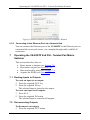
The Local Area Connection Properties window appears.
5. Select the Internet Protocol (TCP/IP) and click the Properties Button
(see Figure 7).
Figure 7: Local Area Connection Properties Window
6. Select Use the following IP Address, and fill in the details as shown in
Figure 8.
7. Click OK.
1 After connecting the Ethernet port, you have to install and configure your Ethernet Port. For detailed instructions, see the
Configuration Guide in the technical support section on our Web site http://www.kramerelectronics.com
13
Operating the VS-88DTP 8x8 DVI - Twisted Pair Matrix Switcher
Figure 8: Internet Protocol (TCP/IP) Properties Window
6.3.2 Connecting to the Ethernet Port via a Network Hub
You can connect the Ethernet port of the VS-88DTP to the Ethernet port on
a network hub or network router, via a straight through cable with RJ-45
connectors.
7
Operating the VS-88DTP 8x8 DVI - Twisted Pair Matrix
Switcher
This section describes how to:
• Route inputs to outputs (see Section 7.1)
• Disconnect outputs (see Section 7.2)
• Store and recall a setup (see Section 7.3)
• Acquire the EDID (see Section 7.5)
7.1 Routing Inputs to Outputs
To route an input to an output:
1. Press the required OUT key.
2. Press the required IN key.
The selected input is routed to the output.
To route one input to all outputs:
1. Press ALL.
2. Press the required IN button.
The selected input is routed to all outputs.
7.2 Disconnecting Outputs
To disconnect one output:
1. Press the required OUT button
14
KRAMER: SIMPLE CREATIVE TECHNOLOGY
Operating the VS-88DTP 8x8 DVI - Twisted Pair Matrix Switcher
2. Press OFF.
The selected output is disconnected.
To disconnect all outputs at once:
1. Press the ALL button.
2. Press OFF.
All outputs are disconnected.
7.3 Storing and Recalling Setups in Presets
You can use the STO and RCL buttons to store and recall up to 16 setups in
presets. Figure 9 illustrates the preset assignment numbers. Preset 1 is
assigned to OUT 1 and preset 16 is assigned to IN 8.
Note: The preset numbers do not appear on the buttons.
Figure 9: Preset Number Assignments using the Selector Buttons
To store a setup:
1. Route inputs and outputs as required.
2. Press the STO button.
The STO button flashes.
3. Select a preset number in which to store the current configuration (for
example, for preset 13, press IN 5).
To recall a setup:
1. Press the RCL button.
The RCL button flashes.
2. Press the required preset button (for example, for preset 13, press
IN 5).
7.4 Switching between Protocol 2000 and Protocol 3000
To switch to Protocol 2000:
• Press the Output 1 and Output 2 buttons at the same time.
The device switches to Protocol 2000 and the display shows 2000.
To switch to Protocol 3000:
• Press the Output 1 and Output 3 buttons at the same time.
The device switches to Protocol 3000 and the display shows 3000.
15
Operating the VS-88DTP 8x8 DVI - Twisted Pair Matrix Switcher
7.5 Acquiring the EDID
You can acquire the EDID from:
• A single connected output (see Section 7.5.1)
• Several outputs (see Section 7.5.2)
• The default EDID (see Section 7.5.3)
7.5.1 Acquiring an EDID from a Single Output
To acquire or change the EDID from a single output:
1. Connect the acceptor to the required output from which you want to
acquire the EDID.
2. Press the EDID button.
The EDID button flashes.
3. Press the SELECT IN button to which the EDID will be copied.
The selected input number flashes on the display.
4. Select the SELECT OUT button from which the EDID will be
acquired.
5. Press the EDID button.
The process is complete when the display returns to normal.
7.5.2 Acquiring an EDID from Several Outputs to Several Inputs
To acquire the EDID from several outputs to several inputs (for
example, OUT 1 to IN 1 and OUT 6 to IN 3):
1. Connect the acceptors to the required outputs from which you want to
acquire the EDIDs.
2. Press the EDID button.
The EDID buttons flashes.
3. Press the SELECT IN button to which the first EDID will be copied
(for example, IN 1).
The selected input number flashes on the display.
4. Press the SELECT OUT button from which the first EDID will be
acquired (for example, OUT 1).
5. Press the SELECT IN 1 button again.
The IN 1 button ceases to flash.
6. Press another SELECT IN to which the next EDID will be copied (for
example, IN 3).
The selected input number flashes on the display.
7. Press the SELECT OUT button from which the next EDID will be
acquired (for example, OUT 6).
8. Press the SELECT IN 3 button again.
The IN 3 button ceases to flash.
16
KRAMER: SIMPLE CREATIVE TECHNOLOGY
Controlling the VS-88DTP Remotely via Ethernet
9. Press the SELECT IN buttons to which you want to copy the EDID
(for example, IN 1 and IN 3).
10. Make sure that the relevant input numbers flash on the display.
11. Press the EDID button.
The process is complete when the display returns to normal.
7.5.3 Acquiring the Default EDID
To reset to the default EDID, do the following:
1. Press the EDID button.
The EDID button flashes.
2. Press the SELECT IN button to which the EDID will be copied.
The selected input number flashes on the display.
3. Press the OFF button until a “0” (zero) appears on the display.
4. Press the EDID button.
The process is complete when the display returns to normal.
7.6 Locking and Unlocking the Front Panel Buttons
To lock and unlock the front panel buttons:
1. Press and hold the LOCK button until the buttons lights.
The front panel buttons are locked.
2. Press and hold the LOCK button until the button no longer lights.
The front panel buttons are unlocked.
7.7 Control Configuration via the Ethernet Port
To control several units via the Ethernet, connect the Master unit
(Machine # 1) via the Ethernet port to the LAN port of your PC. Use your
PC initially to configure the settings (see Section 6.3).
8
Controlling the VS-88DTP Remotely via Ethernet
You can remotely operate the VS-88DTP using a Web browser via the
Ethernet connection (see Section 8.1). To be able to do so, you must use a
supported Web browser; Microsoft (V6.0 and higher), Chrome, Firefox
(V3.0 and higher).
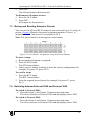
To check that Java is installed and running, browse to:
http://www.java.com/en/download/help/testvm.xml
This page runs a test and displays a Java success (see Figure 10) or failure
message.
17
Controlling the VS-88DTP Remotely via Ethernet
Figure 10: Java Test Page Success Message
If you do not see the success message, follow the instructions on the page
to:
• Load and enable Java
• Enable Javascript in your browser
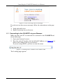
8.1 Connecting to the VS-88DTP via your Browser
Make sure that your PC is connected via a network to the VS-88DTP and
do the following:
1. Open your Internet browser.
2. Enter the unit’s IP number (for the default IP address, see Figure 11) or
name in the Address bar of your browser.
If you are using DHCP, you have to enter the name.
Figure 11: Entering the IP Number in the Address Bar
The Loading page appears.
18
KRAMER: SIMPLE CREATIVE TECHNOLOGY
Controlling the VS-88DTP Remotely via Ethernet
Figure 12: The Loading Page
The first time that you run the Kramer applet a security warning
appears.
Figure 13: First Time Security Warning
3. Click Run.
The main switching control page is displayed which shows a graphical
representation of the front panel (see Figure 14).
There are two remote operation Web pages:
• Main switching matrix (see Section 8.2)
• Configuration (see Section 8.3)
19
Controlling the VS-88DTP Remotely via Ethernet
Select a page by clicking on the relevant link on the left hand side of the
window.
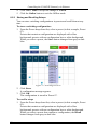
8.2 The Main Switching Matrix Page
Figure 14: Main Switching Matrix Page
The main switching matrix page allows you to:
• Switch any input to any/all outputs independently (see Section 8.2.1)
• Operate the unit in the Offline mode (see Section 8.2.2)
• Use presets to store and recall switching configurations (see
Section 8.2.3)
• Lock or unlock the unit’s front panel buttons (see Section 8.2.4)
8.2.1 Switching an Input to an Output
To switch an input to an output, for example, input 1 to output 4:
1. Click the required point within the switching matrix grid (In 1, Out 4).
20
KRAMER: SIMPLE CREATIVE TECHNOLOGY
Controlling the VS-88DTP Remotely via Ethernet
Figure 15: Selecting a Switching Point on the Matrix
A blue switching icon
appears indicating that the channel is
switched to In 1 and Out 4.
2. Repeat the above steps for each channel that you want to switch.
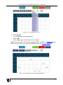
8.2.2 Operating in the Offline Mode
By default, the unit operates in the At-Once mode, meaning that any
switching changes take effect immediately. In the Offline mode, changes
only take effect when you press the Take button.
To operate in the Offline mode:
1. Click the red Offline button.
The button outline becomes dark.
2. Click the required point in the switching matrix grid (In 1, Out 5).
The switching icon outline
appears, and the Take and Cancel
buttons change from gray to dark blue.
Figure 16: Switching in the Offline Mode
3. If required, repeat Step 2 for several channels.
21
Controlling the VS-88DTP Remotely via Ethernet
4. Click either Take to accept the change or Cancel.
5. Click the Online button to exit the Offline mode.
8.2.3 Storing and Recalling Setups
You can store switching configurations in presets and recall them at any
time.
To store a switching configuration:
1. From the Preset drop-down list, select a preset (in this example, Preset
07).
Presets that contain a configuration are displayed with a blue
background; presets with no configuration have a white background.
When you select a preset, the Store button changes from gray to dark
blue.
Figure 17: Selecting Preset 07
2. Click Store.
A confirmation message appears.
3. Click OK.
The configuration is stored in Preset 07.
To recall a setup:
1. From the Preset drop-down list, select a preset (in this example, Preset
03).
Presets that contain a configuration are displayed with a blue
background; presets with no configuration have a white background.
When you select a preset that contains a configuration, the Recall
button changes from gray to dark blue.
22
KRAMER: SIMPLE CREATIVE TECHNOLOGY
Controlling the VS-88DTP Remotely via Ethernet
Figure 18: Selecting Preset 03
2. Click Recall.
A confirmation message appears.
3. Click OK.
The configuration from Preset 03 is loaded.
Note: You can also recall a preset in the Offline mode (see Figure 19) and
make it active when you press the Take button (see Section 8.2.2).
Figure 19: Recalling a Preset in Offline Mode
23
Controlling the VS-88DTP Remotely via Ethernet
8.2.4 Locking the Front Panel Buttons
You can lock the front panel buttons to prevent tampering.
To lock the front panel buttons:
• Click the padlock icon
Note: Locking the front panel buttons does not disable remote operation of
the unit via Ethernet, RS-232 or RS-485.
8.3 The Configuration Page
The Configuration page lets you edit the IP-related settings and only view
the others. Editable fields have a white background.
Figure 20: Configuration Page
The following IP-related settings can be edited:
• Machine name
• Fixed IP Address/DHCP
• Gateway
• Subnet Mask
The following fields can be viewed:
• Model
• Serial Number
• Firmware Version
• MAC Address
To edit the IP-related settings:
1. Edit the required field.
2. Click Submit.
The Network Settings confirmation message appears.
24
KRAMER: SIMPLE CREATIVE TECHNOLOGY
Technical Specifications
3. Click OK.
A message appears showing that the settings have been successfully
changed.
4. If the IP address was changed or you selected DHCP, reload the Web
page using the new name or IP address.
9
Technical Specifications
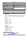
Table 4 lists the technical specifications for the VS-88DTP.
Table 4: VS-88DTP Technical Specifications 1
INPUTS:
OUTPUTS:
BANDWIDTH:
COMPLIANCE WITH
STANDARDS:
MAX RESOLUTION:
POWER SOURCE:
CONTROLS:
OPERATING
TEMPERATURE:
STORAGE
TEMPERATURE:
HUMIDITY:
DIMENSIONS:
WEIGHT:
ACCESSORIES:
OPTIONS:
8 DVI connectors
8 TP on RJ-45 connectors
Up to 1.65Gbps bandwidth per graphic channel
Supports DVI 1.1
Up to UXGA; 1080p, 1920 x 1200
100−240VAC; 50/60Hz, 55VA
Front panel buttons, Infrared remote control transmitter, RS-232, RS-485, Ethernet
0° to +55°C (32° to 131°F)
-45° to +72°C (-49° to 162°F)
10% to 90%, RHL non-condensing
19" x 9.7" x 1U (W, D, H)
2.3kg (5.5lbs) approx.
Power cord, IR transmitter, Rack “ears”
Kramer cables 2; external remote IR receiver cable
10 Default Communication Parameters
Table 5: Default Communication Parameters
EDID
EDID data is passed between Output 1 and Input 1
RS-232
Protocol 2000
Protocol 3000 (Default)
Baud Rate:
9600
Baud Rate:
115,200
Data Bits:
8
Data Bits:
8
Stop Bits:
1
Stop Bits:
1
Parity:
None
Parity:
None
Command Format:
HEX
Command Format:
ASCII
Example (Output 1 to Input 1):
0x01, 0x81, 0x81, 0x81
Example (Output 1 to Input 1): #AV 1>1<CR>
1 Specifications are subject to change without notice
2 For best results, use Kramer cables such as the C-DM-DM series
25
Default EDID
Switching Protocol
P2000 -> P3000
Command:
P3000 -> P2000
0x38, 0x80, 0x83, 0x81
Command:
#P2000<CR>
Ethernet
Default Settings
Reset Settings
IP Address: 192.168.1.39
Power cycle the unit while holding in the Factory Reset
button, located on the rear panel of the unit.
TCP Port #: 5000
UDP Port #: 50000
1
The Windows®-based Kramer control software operates with protocol 2000. If
the VS-88DTP is set to protocol 3000, it is automatically switched to protocol
2000.
11 Default EDID
Each input on the VS-88DTP is loaded with a factory default EDID. The
EDID for each input can be changed independently by uploading an EDID
binary file to each input via the RS-232 port using Kramer EDID Sender
software 2.
Monitor
Model name............... VS-88DTP
Manufacturer............. KRM
Plug and Play ID......... KRM0200
Serial number............ 1
Manufacture date......... 2006, ISO week 12
------------------------EDID revision............ 1.3
Input signal type........ Digital (DVI)
Color bit depth.......... Undefined
Display type............. RGB color
Screen size.............. 700 x 390 mm (31.5 in)
Power management......... Not supported
Extension blocs.......... None
------------------------DDC/CI................... n/a
Color characteristics
Default color space...... Non-sRGB
Display gamma............ 2.20
Red chromaticity......... Rx 0.640 - Ry 0.341
Green chromaticity....... Gx 0.286 - Gy 0.610
Blue chromaticity........ Bx 0.146 - By 0.069
White point (default).... Wx 0.284 - Wy 0.293
Additional descriptors... None
Timing characteristics
Horizontal scan range.... 45-56kHz
Vertical scan range...... 86-83Hz
Video bandwidth.......... 560MHz
CVT standard............. Not supported
GTF standard............. Not supported
1 Download the latest software from our Web site at http://www.kramerelectronics.com
2 Available for download from http://www.kramerelectronics.com
26
KRAMER: SIMPLE CREATIVE TECHNOLOGY
Updating the VS-88DTP Firmware
Additional descriptors... None
Preferred timing......... Yes
Native/preferred timing.. 1280x768p at 60Hz (4:3)
Modeline............... "1280x768" 79.500 1280 1344 1472 1664 768 771 778 798 +hsync +vsync
Detailed timing #1....... 1920x1200p at 60Hz (16:10)
Modeline............... "1920x1200" 154.000 1920 1968 2000 2080 1200 1203 1209 1235 +hsync -vsync
Standard timings supported
720 x 400p at 70Hz - IBM VGA
720 x 400p at 88Hz - IBM XGA2
640 x 480p at 60Hz - IBM VGA
640 x 480p at 67Hz - Apple Mac II
640 x 480p at 72Hz - VESA
640 x 480p at 75Hz - VESA
800 x 600p at 56Hz - VESA
800 x 600p at 60Hz - VESA
800 x 600p at 72Hz - VESA
800 x 600p at 75Hz - VESA
832 x 624p at 75Hz - Apple Mac II
1024 x 768i at 87Hz - IBM
1024 x 768p at 60Hz - VESA
1024 x 768p at 70Hz - VESA
1024 x 768p at 75Hz - VESA
1280 x 1024p at 75Hz - VESA
1152 x 870p at 75Hz - Apple Mac II
1360 x 765p at 60Hz - VESA STD
1280 x 800p at 60Hz - VESA STD
1440 x 900p at 60Hz - VESA STD
1280 x 960p at 60Hz - VESA STD
1280 x 1024p at 60Hz - VESA STD
1400 x 1050p at 60Hz - VESA STD
1680 x 1050p at 60Hz - VESA STD
1600 x 1200p at 60Hz - VESA STD
Report information
Date generated........... 21-Jun-11
Software revision........ 2.53.0.861
Data source.............. File
Operating system......... 5.1.2600.2.Service Pack 3
Raw data
00,FF,FF,FF,FF,FF,FF,00,2E,4D,00,02,01,00,00,00,0C,10,01,03,81,46,27,78,0A,D5,7C,A3,57,49,9C,25,
11,48,4B,FF,FF,80,8B,C0,81,00,95,00,81,40,81,80,90,40,B3,00,A9,40,0E,1F,00,80,51,00,1E,30,40,80,
37,00,6F,13,11,00,00,1E,28,3C,80,A0,70,B0,23,40,30,20,36,00,06,44,21,00,00,1A,00,00,00,FC,00,56,
53,2D,38,38,44,54,50,0A,20,20,20,20,00,00,00,FD,00,56,53,2D,38,38,44,54,50,0A,20,20,20,20,00,83
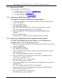
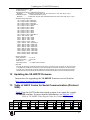
12 Updating the VS-88DTP Firmware
Instructions for upgrading the VS-88DTP firmware can be found at
http://www.kramerelectronics.com.
13 Table of ASCII Codes for Serial Communication (Protocol
3000)
Table 6 lists the ASCII codes that switch an input to an output for a single
VS-88DTP machine. For more detailed information, see Section 15.2.
Table 6: VS-88DTP Video Signal Codes for Protocol 3000
OUT 1
OUT 2
OUT 3
OUT 4
OUT 5
OUT 6
OUT 7
OUT 8
IN 1 #V 1>1 CR #V 1>2 CR #V 1>3 CR #V 1>4 CR #V 1>5 CR #V 1>6 CR #V 1>7 CR #V 1>8 CR
IN 2 #V 2>1 CR #V 2>2 CR #V 2>3 CR #V 2>4 CR #V 2>5 CR #V 2>6 CR #V 2>7 CR #V 2>8 CR
IN 3 #V 3>1 CR #V 3>2 CR #V 3>3 CR #V 3>4 CR #V 3>5 CR #V 3>6 CR #V 3>7 CR #V 3>8 CR
27
Hex Codes for Serial Communication (Protocol 2000)
OUT 1
OUT 2
OUT 3
OUT 4
OUT 5
OUT 6
OUT 7
OUT 8
IN 4 #V 4>1 CR #V 4>2 CR #V 4>3 CR #V 4>4 CR #V 4>5 CR #V 4>6 CR #V 4>7 CR #V 4>8 CR
IN 5 #V 5>1 CR #V 5>2 CR #V 5>3 CR #V 5>4 CR #V 5>5 CR #V 5>6 CR #V 5>7 CR #V 5>8 CR
IN 6 #V 6>1 CR #V 6>2 CR #V 6>3 CR #V 6>4 CR #V 6>5 CR #V 6>6 CR #V 6>7 CR #V 6>8 CR
IN 7 #V 7>1 CR #V 7>2 CR #V 7>3 CR #V 7>4 CR #V 7>5 CR #V 7>6 CR #V 7>7 CR #V 7>8 CR
IN 8 #V 8>1 CR #V 8>2 CR #V 8>3 CR #V 8>4 CR #V 8>5 CR #V 8>6 CR #V 8>7 CR #V 8>8 CR
14 Hex Codes for Serial Communication (Protocol 2000)
The Hex codes listed in this section are used to set video channels for a
single machine (set as Machine 1) connected via either RS-232 or Ethernet.
Similar hex codes are used when the VS-88DTP is connected via RS-485
and the machine is set to number 2.
Table 7 lists the Hex codes that switch video channels:
Table 7: VS-88DTP Hex Codes for Switching via RS-232/RS-485
OUT 1
OUT 2
OUT 3
Switching Video Channels
OUT 4
OUT 5
OUT 6
OUT 7
OUT 8
01 81 81 81 01 81 82 81 01 81 83 81 01 81 84 81 01 81 85 81 01 81 86 81 01 81 87 81 01 81 88 81
01 82 81 81 01 82 82 81 01 82 83 81 01 82 84 81 01 82 85 81 01 82 86 81 01 82 87 81 01 82 88 81
IN 1
IN 2
IN 3
IN 4
IN 5
IN 6
IN 7
IN 8
01 83 81 81 01 83 82 81 01 83 83 81 01 83 84 81 01 83 85 81 01 83 86 81 01 83 87 81 01 83 88 81
01 84 81 81 01 84 82 81 01 84 83 81 01 84 84 81 01 84 85 81 01 84 86 81 01 84 87 81 01 84 88 81
01 85 81 81 01 85 82 81 01 85 83 81 01 85 84 81 01 85 85 81 01 85 86 81 01 85 87 81 01 85 88 81
01 86 81 81 01 86 82 81 01 86 83 81 01 86 84 81 01 86 85 81 01 86 86 81 01 86 87 81 01 86 88 81
01 87 81 81 01 87 82 81 01 87 83 81 01 87 84 81 01 87 85 81 01 87 86 81 01 87 87 81 01 87 88 81
01 88 81 81 01 88 82 81 01 88 83 81 01 88 84 81 01 88 85 81 01 88 86 81 01 88 87 81 01 88 88 81
15 Kramer Protocol
By default, the VS-88DTP is set to protocol 3000 (see Section 15.2) but is
also compatible with Kramer’s Protocol 2000 1 (see Section 15.3).
Section 15.1 describes how to switch between protocol 3000 and protocol
2000.
18F
15.1 Switching Protocols
You can switch protocols either via the front panel buttons (see
Section 15.1.1) or the protocol commands.
15.1.1 Switching Protocols via the Front Panel Buttons
47B
To switch from protocol 3000 to protocol 2000, press and hold 2 the OUT 1
and OUT 2 buttons for a few seconds.
19F
1 You can download our user-friendly “Software for Calculating Hex Codes for Protocol 2000” from the technical support
section on our Web site at: http://www.kramerelectronics.com
2 Not as part of a switching operation
28
KRAMER: SIMPLE CREATIVE TECHNOLOGY
Kramer Protocol
The display shows 2000.
To switch from protocol 2000 to protocol 3000, press and hold the OUT 1
and OUT 3 buttons for a few seconds.
The display shows 3000.
15.2 Kramer Protocol 3000
This RS-232/RS-485 communication protocol lets you control the machine
from any standard terminal software (for example, Windows®
HyperTerminal).
15.2.1 Host Message Format
Start
Address (optional)
Body
Delimiter
#
Destination_id@
Message
CR
15.2.1.1 Simple Command
Command string with only one command without addressing:
Start
Body
Delimiter
#
Command SP Parameter_1,Parameter_2,…
CR
15.2.1.2 Command String
Formal syntax with commands concatenation and addressing:
Start
Address
Body
Delimiter
#
Destination_id@
Command_1 Parameter1_1,Parameter1_2,…|
Command_2 Parameter2_1,Parameter2_2,…|
Command_3 Parameter3_1,Parameter3_2,…|…
CR
15.2.2 Device Message Format
Start
Address (optional)
Body
delimiter
~
Sender_id@
Message
CR LF
15.2.2.1 Device Long Response
Echoing command:
Start
Address (optional)
Body
Delimiter
~
Sender_id@
Command SP [Param1 ,Param2 …] result
CR LF
CR = Carriage return (ASCII 13 = 0x0D)
LF = Line feed (ASCII 10 = 0x0A)
SP = Space (ASCII 32 = 0x20)
15.2.3 Command Terms
Command
A sequence of ASCII letters ('A'-'Z', 'a'-'z' and '-').
Command and parameters must be separated by at least one space.
29
Kramer Protocol
Parameters
A sequence of alphameric ASCII characters ('0'-'9','A'-'Z','a'-'z' and some
special characters for specific commands). Parameters are separated by
commas.
Message string
Every command entered as part of a message string begins with a message
starting character and ends with a message closing character.
Note: A string can contain more than one command. Commands are
separated by a pipe ( '|' ) character.
Message starting character
'#' – For host command/query
'~' – For machine response
Device address (Optional when directly connected to the device)
K-NET Device ID or MACHINE NUMBER followed by '@'
(ex. #02@ CRLF )
Query sign
'?' follows some commands to define a query request.
All outputs sign
'*' defines all outputs.
Message closing character
CR – For host messages; carriage return (ASCII 13)
CRLF – For machine messages; carriage return (ASCII 13) + line-feed
(ASCII 10)
Command chain separator character
When a message string contains more than one command, a pipe ( '|' )
character separates each command.
Spaces between parameters or command terms are ignored.
15.2.4 Entering Commands
You can directly enter all commands using a terminal with ASCII
communications software, such as HyperTerminal, Hercules, etc. Connect
the terminal to the serial, Ethernet, or USB port on the Kramer device. To
enter CR , press the Enter key.
( LF is also sent but is ignored by command parser).
For commands sent from some non-Kramer controllers like Crestron, some
characters require special coding (such as, /X##). Refer to the controller
manual.
15.2.5 Command Forms
Some commands have short name syntax in addition to long name syntax to
allow faster typing. The response is always in long syntax.
30
KRAMER: SIMPLE CREATIVE TECHNOLOGY
Kramer Protocol
15.2.6 Command Chaining
Multiple commands can be chained in the same string. Each command is
delimited by a pipe character ( '|' ). When chaining commands, enter the
message starting character and the message closing character only once,
at the beginning of the string and at the end.
Commands in the string do not execute until the closing character is
entered.
A separate response is sent for every command in the chain.
15.2.7 Maximum String Length
64 characters
15.2.8 Backward Support
You can switch between protocols using a switch protocol command from
either platform.
Table 8: Instruction Codes for Protocol 3000
Command
Protocol Handshaking
Help commands
Syntax
#CR
Response
~OKCRLF
Device initiated messages
Command
Syntax
Start message
~Protocol start CRLF
Switcher actions
Video channel has switched (AFV mode)
AV IN>OUT
Result codes (errors)
Syntax
COMMAND PARAMETERS OK
No error. Command running succeeded
Protocol Errors
ERR001
Syntax Error
Command not available for this device
ERR002
Parameter is out of range
ERR003
Unauthorized access (running command without the match login).
ERR004
Command
Switch video
Basic routing commands
Syntax
Response
AV IN>OUT, IN>OUT, …
AV IN>OUT, IN>OUT,…RESULT
OR
Switch video only
VID IN>OUT, IN>OUT, …
Short form: V IN>OUT, IN>OUT, …
AV IN>OUT, IN>OUT, …RESULT
Note:
When AFV mode is active, this command will switch also audio. If audio is breakaway – device display mode will
change to show audio connections status.
31
Kramer Protocol
Basic routing commands
Note: When AFV mode is active, this command will switch also video.
Read video
connection
VID? OUT
Short form: V? OUT
VID? *
VID IN>OUT
VID IN>1, IN>2, …
Parameters Description:
IN = Input number or '0' to disconnect output.
'>' = Connection character between in and out parameters.
OUT = Output number or '*' for all outputs.
Examples:
Switch Video and Audio input 3 to output 7 #AV 3>7CR
~AV 3>7 OKCRLF
Switch Video input 2 to output 4
#V 2>4CR
~AV 2>4 OKCRLF
Switch Video input 4 to output 2 in
machine number 6
#6@VID 4>2CR
~6@AV 4>2 OKCRLF
Disconnect Video and Audio Output 4
#AV 0>4CR
~AV 0>4 OKCRLF
Switch Video Input 3 to All Outputs
#V 3>*CR
~AV 3>* OKCRLF
Chaining Multiple
commands*
Command
Store current
connections to preset
#AV 1>* | V 3>4, 2>2, 82>1, 0>2 |V 82>3| V? * CR
First switch all Audio and video outputs from input 1,
Then switch video input 3 to output 4, video input 2 to output
2, video input and disconnect video output 2.
Then switch audio input 3 to output 2,
Then disconnect audio output 1.
Then get status of all links (assume this is 4x4 matrix).
Commands processing start after entering CR, response will sent
for each command after processing it.
~AV 1>* OKCRLF
~AV 1>2, 3>4
OKCRLF
~AV 82>3 ERR###
CRLF
~AUD 0>1 OKCRLF
~AV 1>1, 0>2, 1>3,
3>4 CRLF
Preset commands
Syntax
Response
PRST-STO PRESET
PRST-STO PRESET RESULT
Short form: PSTO PRESET
Recall saved preset
PRST-RCL PRESET
Short form: PRCL PRESET
PRST-RCL PRESET RESULT
Read video
connections from
saved preset
PRST-VID? PRESET,OUT
Short form: PVID? PRESET,OUT
PRST-VID? PRESET, *
PRST-VID PRESET, IN>OUT
PRST-VID PRESET, IN>1, IN>2,…
Parameters Description:
PRESET = Preset number.
OUT = Output in preset to show for, '*' for all.
Store current Audio & Video
connections to preset 5
32
Examples:
#PRST-STR 5CR
~PRST-STR 5 OKCRLF
KRAMER: SIMPLE CREATIVE TECHNOLOGY
Kramer Protocol
Recall Audio & Video
connections from preset 3
#PRCL 3CR
~PRST-RCL 3 OKCRLF
Show source of video output 2
from preset 3
#PRST-VID? 3,2CR
~PRST-VID 3: 4>2 CRLF
Operation commands
Syntax
LOCK-FP LOCK-MODE
Short form: LCK LOCK-MODE
Response
LOCK-FP LOCK-MODE RESULT
LOCK-FP?
LOCK-FP LOCK-MODE
Command
Lock front panel
Get front panel locking state
Parameters Description:
LOCK-MODE = Front panel locking state:
"0" or "off" to unlock front panel buttons.
"1" or "on" to lock front panel buttons.
Restart device
RESET
RESET OK
Switch to protocol 2000*
P2000
P2000 OK
* Protocol 2000 has command to switch back to ASCII protocol (like protocol 3000)
Machine info commands
Command
Syntax
Response
* Time settings commands require admin authorization
Read in\outs count INFO-IO?
INFO-IO: IN INPUTS_COUNT, OUT OUTPUTS_COUNT
Read max presets
count
Reset
configuration to
factory default
INFO-PRST?
INFO-PRST: VID PRESET_VIDEO_COUNT, AUD
PRESET_AUDIO_COUNT
FACTORY
FACTORY RESULT
Identification commands
Syntax
Command
Protocol Handshaking
Read device model
#CR
~OK CRLF
MODEL?
MODEL MACHINE_MODEL
Read device serial number SN?
Read device firmware
version
Set machine name
Read machine name
Reset machine name to
factory default*
Response
SN SERIAL_NUMBER
VERSION?
VERSION MAJOR .MINOR .BUILD .REVISION
NAME MACHINE_NAME
NAME MACHINE_NAME RESULT
NAME?
NAME MACHINE_NAME
NAME-RST
NAME-RST MACHINE_FACTORY_NAME
RESULT
*Note: machine name not equal to model name. This name relevance for site viewer identification of specific
machine or for network using (with DNS feature on).
33
Kramer Protocol
Identification commands
Command
Syntax
MACHINE_NAME = Up to 14 Alfa-Numeric chars.
* Machine factory name = Model name + last 4 digits from serial number.
Set IP Address
Read IP Address
Read MAC Address
Set subnet mask
Read subnet mask
Set gateway address
Read subnet mask
Set DHCP mode
Read subnet mask
Response
Network settings commands
NET-IP IP_ADDRESS
NET-IP IP_ADDRESS RESULT
NTIP
NET-IP?
NTIP?
NET-IP IP_ADDRESS
NET-MAC?
NTMC
NET-MAC MAC_ADDRESS
NET-MASK SUBNET_MASK
NTMSK
NET-MASK SUBNET_MASK RESULT
NET-MASK?
NTMSK?
NET-MASK SUBNET_MASK
NET-GATE GATEWAY_ADDRESS
NTGT
NET-GATE?
NTGT?
NET-GATE GATEWAY_ADDRESS RESULT
NET-DHCP DHCP_MODE
NTDH
NET-DHCP DHCP_MODE RESULT
NET-DHCP?
NTDH?
NET-DHCP DHCP_MODE
NET-GATE GATEWAY_ADDRESS
DHCP_MODE =
0 – Don't use DHCP (Use IP set by factory or IP set command).
1 – Try to use DHCP, if unavailable use IP as above.
Change protocol
ethernet port
Read protocol
ethernet port
ETH-PORT PROTOCOL , PORT
ETHP
ETH-PORT PROTOCOL ,PORT RESULT
ETH-PORT? PROTOCOL
ETHP?
ETH-PORT PROTOCOL , PORT
PROTOCOL = TCP / UDP (transport layer protocol)
PORT = ethernet port to enter protocol 3000 commands.
1-65535 = User defined port
0 - reset port to factory default (50000 for UDP, 5000 for TCP)
34
KRAMER: SIMPLE CREATIVE TECHNOLOGY
Kramer Protocol
15.3 Kramer Protocol 2000
This RS-232/RS-485 communication protocol uses four bytes of
information as defined below. The default data rate is 115200 baud, with no
parity, 8 data bits and 1 stop bit.
Table 9: Protocol Definitions
MSB
LSB
DESTINATION
INSTRUCTION
0
D
N5
N4
N3
N2
N1
N0
7
6
5
4
3
2
1
0
1
I6
I5
I4
I3
I2
I1
I0
7
6
5
4
3
2
1
0
1
O6
O5
O4
O3
O2
O1
O0
7
6
5
4
3
2
1
0
1
OVR
X
M4
M3
M2
M1
M0
7
6
5
4
3
2
1
0
1st byte
INPUT
2nd byte
OUTPUT
3rd byte
MACHINE NUMBER
4th byte
Bit 7 – Defined as 0.
1st BYTE:
D – “DESTINATION”:
0 - for sending information to the switchers (from the PC);
1 - for sending to the PC (from the switcher).
N5…N0 – “INSTRUCTION”
The function that is to be performed by the switcher(s) is defined by the INSTRUCTION (6 bits). Similarly, if a function is
performed via the machine’s keyboard, then these bits are set with the INSTRUCTION NO., which was performed. The
instruction codes are defined according to the table below (INSTRUCTION NO. is the value to be set for N5…N0).
2nd BYTE:
Bit 7 – Defined as 1.
I6…I0 – “INPUT”.
When switching (ie. instruction codes 1 and 2), the INPUT (7 bits) is set as the input number which is to be switched.
Similarly, if switching is done via the machine’s front-panel, then these bits are set with the INPUT NUMBER which was
switched. For other operations, these bits are defined according to the table.
3rd BYTE:
Bit 7 – Defined as 1.
O6…O0 – “OUTPUT”.
When switching (ie. instruction codes 1 and 2), the OUTPUT (7 bits) is set as the output number which is to be switched.
Similarly, if switching is done via the machine’s front-panel, then these bits are set with the OUTPUT NUMBER which was
switched. For other operations, these bits are defined according to the table.
4th BYTE:
Bit 7 – Defined as 1.
Bit 5 – Don’t care.
OVR – Machine number override.
M4…M0 – MACHINE NUMBER.
Used to address machines in a system via their machine numbers. When several machines are controlled from a single serial
port, they are usually configured together with each machine having an individual machine number. If the OVR bit is set, then
all machine numbers will accept (implement) the command, and the addressed machine will reply.
For a single machine controlled via the serial port, always set M4…M0 = 1, and make sure that the machine itself is
configured as MACHINE NUMBER = 1.
35
Kramer Protocol
Table 10: Instruction Codes for Protocol 2000
Note: All values in the table are decimal, unless otherwise stated.
#
INSTRUCTION
DESCRIPTION
DEFINITION FOR SPECIFIC INSTRUCTION
INPUT
OUTPUT
RESET VIDEO
0
1
SWITCH VIDEO
3
STORE VIDEO STATUS
Set equal to video input
which is to be switched
(0 = disconnect)
Set as SETUP #
4
RECALL VIDEO STATUS
Set as SETUP #
Set as SETUP #
16
REQUEST STATUS OF A
VIDEO OUTPUT
REQUEST WHETHER SETUP
IS DEFINED / VALID INPUT IS
DETECTED
ERROR / BUSY
30
LOCK FRONT PANEL
31
REQUEST WHETHER PANEL
IS LOCKED
CHANGE TO ASCII
0 - Panel unlocked
1 - Panel locked
0
0
5
15
56
61
62
IDENTIFY MACHINE
DEFINE MACHINE
SETUP #
or
Input #
For invalid / valid input
(i.e. OUTPUT byte = 4
or OUTPUT byte = 5),
this byte is set as the
input #
0
NOTE
1
Set equal to video output which is 2
to be switched
(0 = to all the outputs)
0 - to store
2, 3
1 - to delete
0
2, 3
Equal to output number whose
4, 3
status is reqd
0 - for checking if setup is defined 8
1 - for checking if input is valid
9, 25
0 - error
1 - invalid instruction
2 - out of range
3 - machine busy
4 - invalid input
5 - valid input
6 - RX buffer overflow
0
2
0
16
0
Kramer protocol 3000
19
1 - video machine name
2 - audio machine name
3 - video software version
4 - audio software version
0 - Request first 4 digits
1 - Request first suffix
2 - Request second suffix
3 - Request third suffix
10 - Request first prefix
11 - Request second prefix
12 - Request third prefix
13
1 - number of inputs
2 - number of outputs
3 - number of setups
1 - for video
2 - for audio
14
NOTES on the above table:
NOTE 1 - When the master switcher is reset, (e.g. when it is turned on), the reset code is sent to the PC. If this code is sent to
the switchers, it will reset according to the present power-down settings.
NOTE 2 - These are bi-directional definitions. That is, if the switcher receives the code, it will perform the instruction; and if
the instruction is performed (due to a keystroke operation on the front panel), then these codes are sent. For example, if the
HEX code
01
85
88
83
was sent from the PC, then the switcher (machine 3) will switch input 5 to output 8. If the user switched input 1 to output 7
via the front panel keypad, then the switcher will send HEX codes:
41
81
87
83
to the PC.
When the PC sends one of the commands in this group to the switcher, then, if the instruction is valid, the switcher replies by
sending to the PC the same four bytes that it was sent (except for the first byte, where the DESTINATION bit is set high).
NOTE 3 - SETUP # 0 is the present setting. SETUP # 1 and higher are the settings saved in the switcher's memory, (i.e. those
used for Store and Recall).
NOTE 4 - The reply to a "REQUEST" instruction is as follows: the same instruction and INPUT codes as were sent are
returned, and the OUTPUT is assigned the value of the requested parameter. The replies to instructions 10 and 11 are as per
the definitions in instructions 7 and 8 respectively. For example, if the present status of machine number 5 is breakaway
setting, then the reply to the HEX code
0B
80
would be HEX codes
4B
80
36
80
85
81
85
KRAMER: SIMPLE CREATIVE TECHNOLOGY
Kramer Protocol
NOTE 6 – If INPUT is set to 127 for these instructions, then, if the function is defined on this machine, it replies with
OUTPUT=1. If the function is not defined, then the machine replies with OUTPUT=0, or with an error (invalid instruction
code).
If the INPUT is set to 126 for these instructions, then, if possible, the machine will return the current setting of this function,
even for the case that the function is not defined. For example, for a video switcher which always switches during the VIS of
input #1, (and its VIS setting cannot be programmed otherwise), the reply to the HEX code
0A
FE
80
81 (ie. request VIS setting, with INPUT set as 126dec)
would be HEX codes
4A
FE
81
81 (ie. VIS setting = 1, which is defined as VIS from input #1).
NOTE 8 - The reply is as in TYPE 3 above, except that here the OUTPUT is assigned with the value 0 if the setup is not
defined / no valid input is detected; or 1 if it is defined / valid input is detected.
NOTE 9 - An error code is returned to the PC if an invalid instruction code was sent to the switcher, or if a parameter
associated with the instruction is out of range (e.g. trying to save to a setup greater than the highest one, or trying to switch an
input or output greater than the highest one defined). This code is also returned to the PC if an RS-232 instruction is sent
while the machine is being programmed via the front panel. Reception of this code by the switcher is not valid.
NOTE 13 - This is a request to identify the switcher/s in the system. If the OUTPUT is set as 0, and the INPUT is set as 1, 2,
5 or 7, the machine will send its name. The reply is the decimal value of the INPUT and OUTPUT. For example, for a 2216,
the reply to the request to send the audio machine name would be (HEX codes):
7D
96
90
81 (i.e. 128dec+ 22dec for 2nd byte, and 128dec+ 16dec for 3rd byte).
If the request for identification is sent with the INPUT set as 3 or 4, the appropriate machine will send its software version
number. Again, the reply would be the decimal value of the INPUT and OUTPUT - the INPUT representing the number in
front of the decimal point, and the OUTPUT representing the number after it. For example, for version 3.5, the reply to the
request to send the version number would be (HEX codes):
7D
83
85
81 (i.e. 128dec+ 3dec for 2nd byte, 128dec+ 5dec for 3rd byte).
If the OUTPUT is set as 1, then the ASCII coding of the lettering following the machine’s name is sent. For example, for the
VS-7588YC, the reply to the request to send the first suffix would be (HEX codes):
7D
D9
C3
81 (i.e. 128dec+ ASCII for “Y”; 128dec+ ASCII for “C”).
NOTE 14 - The number of inputs and outputs refers to the specific machine which is being addressed, not to the system. For
example, if six 16X16 matrices are configured to make a 48X32 system (48 inputs, 32 outputs), the reply to the HEX code
3E
82
81
82 (ie. request the number of outputs)
would be HEX codes
7E
82
90
82
ie. 16 outputs
NOTE 16 - The reply to the “REQUEST WHETHER PANEL IS LOCKED” is as in NOTE 4 above, except that here the
OUTPUT is assigned with the value 0 if the panel is unlocked, or 1 if it is locked.
NOTE 19 – After this instruction is sent, the unit will respond to the ASCII command set defined by the OUTPUT byte. The
ASCII command to operate with the HEX command set must be sent in order to return to working with HEX codes.
NOTE 25 – For units which detect the validity of the video inputs, Instruction 16 will be sent whenever the unit detects a
change in the state of an input (in real-time).
For example, if input 3 is detected as invalid, the unit will send the HEX codes
10
83
84
81
If input 7 is detected as valid, then the unit will send HEX codes
10
87
85
81.
37
LIMITED WARRANTY
We warrant this product free from defects in material and workmanship under the following terms.
HOW LONG IS THE WARRANTY
Labor and parts are warranted for three years from the date of the first customer purchase.
WHO IS PROTECTED?
Only the first purchase customer may enforce this warranty.
WHAT IS COVERED AND WHAT IS NOT COVERED
Except as below, this warranty covers all defects in material or workmanship in this product. The following are not
covered by the warranty:
1. Any product which is not distributed by us or which is not purchased from an authorized Kramer dealer. If you are
uncertain as to whether a dealer is authorized, please contact Kramer at one of the agents listed in the Web site
www.kramerelectronics.com.
2. Any product, on which the serial number has been defaced, modified or removed, or on which the WARRANTY VOID
IF TAMPERED sticker has been torn, reattached, removed or otherwise interfered with.
3. Damage, deterioration or malfunction resulting from:
i) Accident, misuse, abuse, neglect, fire, water, lightning or other acts of nature
ii) Product modification, or failure to follow instructions supplied with the product
iii) Repair or attempted repair by anyone not authorized by Kramer
iv) Any shipment of the product (claims must be presented to the carrier)
v) Removal or installation of the product
vi) Any other cause, which does not relate to a product defect
vii) Cartons, equipment enclosures, cables or accessories used in conjunction with the product
WHAT WE WILL PAY FOR AND WHAT WE WILL NOT PAY FOR
We will pay labor and material expenses for covered items. We will not pay for the following:
1. Removal or installations charges.
2. Costs of initial technical adjustments (set-up), including adjustment of user controls or programming. These costs are
the responsibility of the Kramer dealer from whom the product was purchased.
3. Shipping charges.
HOW YOU CAN GET WARRANTY SERVICE
1. To obtain service on you product, you must take or ship it prepaid to any authorized Kramer service center.
2. Whenever warranty service is required, the original dated invoice (or a copy) must be presented as proof of
warranty coverage, and should be included in any shipment of the product. Please also include in any mailing a
contact name, company, address, and a description of the problem(s).
3. For the name of the nearest Kramer authorized service center, consult your authorized dealer.
LIMITATION OF IMPLIED WARRANTIES
All implied warranties, including warranties of merchantability and fitness for a particular purpose, are limited in duration
to the length of this warranty.
EXCLUSION OF DAMAGES
The liability of Kramer for any effective products is limited to the repair or replacement of the product at our option. Kramer
shall not be liable for:
1. Damage to other property caused by defects in this product, damages based upon inconvenience, loss of use of the
product, loss of time, commercial loss; or:
2. Any other damages, whether incidental, consequential or otherwise. Some countries may not allow limitations on
how long an implied warranty lasts and/or do not allow the exclusion or limitation of incidental or consequential
damages, so the above limitations and exclusions may not apply to you.
This warranty gives you specific legal rights, and you may also have other rights, which vary from place to place.
NOTE : All products returned to Kramer for service must have prior approval. This may be obtained from your dealer.
This equipment has been tested to determine compliance with the requirements of:
EN-50081:
EN-50082:
CFR-47:
"Electromagnetic compatibility (EMC);
generic emission standard.
Part 1: Residential, commercial and light industry"
"Electromagnetic compatibility (EMC) generic immunity standard.
Part 1: Residential, commercial and light industry environment".
FCC* Rules and Regulations:
Part 15: “Radio frequency devices
Subpart B Unintentional radiators”
CAUTION!
Servicing the machines can only be done by an authorized Kramer technician. Any user who makes changes or
modifications to the unit without the expressed approval of the manufacturer will void user authority to operate the
equipment.
Use the supplied DC power supply to feed power to the machine.
Please use recommended interconnection cables to connect the machine to other components.
* FCC and CE approved using STP cable (for twisted pair products)
38
KRAMER: SIMPLE CREATIVE TECHNOLOGY
For the latest information on our products and a list of
Kramer distributors visit www.kramerelectronics.com
where updates to this user manual may be found.
We welcome your questions, comments and feedback.
Safety Warning:
Disconnect the unit from the power supply before
opening/servicing.
Caution
Kramer Electronics, Ltd.
Web site: www.kramerelectronics.com
E-mail: [email protected]
P/N: 2900-000749 REV 1