1
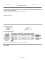
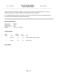
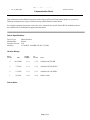
IP Link® Device Interface
Communication Sheet
krmr_15_4866_4.pke
Revision: 1/9/2013
This document provides additional assistance with wiring your Extron IP Link enabled product to your device.
Different components may require a different wiring scheme than those listed below.
For complete operating instructions, refer to the user's manual for the specific Extron IP Link enabled product or
the controlled device manufacturer supplied documentation.
Device Specifications:
Device Type:
Manufacturer:
Firmware Version:
Model(s):
Matrix Switcher
Kramer
N/A
VS-88 DVI, VS-88HD, VS-88V, VS-88H
Version History:
Driver
Version
Date
IP Link
Compiler
GC
Version
Notes
4
01/08/2012
1.5.1
3.3.2
Added model VS-88H.
3
7/3/2012
1.5.1
3.3.2
Added model VS-88 DVI.
2
3/7/2012
1.5.1
3.3.1
Added model VS-88HD.
1
2/9/2011
1.4.0
3.0.4
Initial version.
Driver Notes:
Page 1 of 4
krmr_15_4866_4.pke
IP Link® Device Interface
Communication Sheet
Revision: 1/9/2013
Configuring input output(s) ties on a single button:
This section will describe how to configure a MLC/TLP front panel button with either a single input and
output tie or single input to multiple output ties. Please note that there are a minimum of three selections
required when configuring a tie in this method.
To configure a MLC/TLP front panel button with a single input and a single output tie follow the steps
below.
1. Select the desired input from the “Input” command.
2. Select the desired output from the “Output” command.
3. Select ‘Execute’ from the “Take” command.
To configure a MLC/TLP front panel button with multiple inputs and outputs repeat the steps above then
follow the steps below.
1. Insert a one second delay.
2. Select the next desired output from the “output” command.
3. Select ‘Execute’ from the “Take” command.
Configuring for direct matrix front panel emulation:
This section will describe how to configure a MLC front panel to produce an input output selection
capability.
To configure a MLC front panel button input, create the following button operation.
1. Select the desired input from the “input” command.
To configure a MLC front panel button output, create the following button operations.
1. Select the desired output from the “output” command.
2. Select ‘Execute’ from the “Take” command.
Page 2 of 4
IP Link® Device Interface
Communication Sheet
krmr_15_4866_4.pke
Revision: 1/9/2013
Control Commands & States:
Executive Mode
On
Off
Input
1–8
Break
Machine Number
1–8
Output
1–8
Preset Recall
1–8
Preset Save
1–8
Take
Execute
All
Status Available:
Connection Status
Connected
Disconnected
Executive Mode
On
Off
Output 1 – 8
Input Number*
*Input Number 0 means that there is not tie to the output. If Connection Status state is “Disconnected”, it means
that status is unavailable for the outputs.
MLC60 Series Supported Commands*:
Executive Mode
On
Preset Recall
1–8
Preset Save
1–8
Off
*Uses Machine Number 1. User defined commands are recommended for any unsupported commands.
Page 3 of 4
krmr_15_4866_4.pke
IP Link® Device Interface
Communication Sheet
Cable and Adapter Requirements:
M/F RS-232 straight serial cable (Extron Electronics P/N 26-433-XX)
Notes for the Device:
Serial communication:
Port Type: RS-232
Baud Rate: 9600
Data Bits: 8
Parity: None
Stop Bits: 1
Flow Control: None
Pin Assignments Diagram:
Note: Captive screw connector may also be used as a serial connection.
General Notes:
Page 4 of 4
Revision: 1/9/2013