1
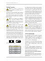
JBL Professional® IndustryAmp User Manual rev 2.1 necessary. (If there is any doubt about which pins should be terminated, shorting all five pins will generally be equally effective.) Failure relay The IndustryAmp includes a single-pole changeover relay whose contacts are accessible on a 3-pole 3.81 mm-pitch screw terminal connector. The conditions under which the relay operates are defined as part of the amplifier configuration in WinControl. The relay connections may be configured either as volt-free, or with additional internal resistors to allow them to be connected directly to impedance-sensing line monitoring equipment such as the JBL Professional® Cerberus*. This selection is made by moving an internal PCB jumper. See “fig.7: Failure relay”. In volt-free operation, CO is connected to NC; a failure condition causes CO to be connected to NO. When configured for impedance-sensing use, the impedance between CO and NC is 10k Ω and open-circuit between CO and NO in normal operation. When a fault condition occurs, the impedance between CO and NC rises to 20k Ω, and CO is short-circuited to NO. A JBL Professional® Cerberus or other impedance-sensing fault monitoring equipment may be connected to CO and NC. The contact wiring arrangement is shown in “fig.7: Failure relay”. The relay contacts have maximum current and voltage ratings of 100 mA and 24 V respectively. fig.7: Failure relay Configuration Jumper Notes Volt-free Towards rear Factory default Impedance-sensing Towards front - *Amplifiers with early serial numbers do not have the option of re-configuring the volt-free relay contacts for impedance-sensing operation. Please contact your JBL Professional® distributor if there is any doubt which model you have. 201104/IAMP_2.1 15