1
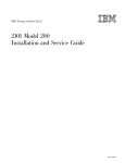
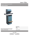
MINISTRY OF EDUCATION AND TRAINING Capstone Project Document System for Testing Hardware Device Nguyễn Viết Cường SE02203 Trần Quang Minh SE02142 Group Members Trần Nam Lâm SE02048 Nguyễn Khắc Hoàng SE02412 Nguyễn Mạnh Hùng SE02087 Supervisor Mr. Phan Duy Hùng Capstone Project Code STHD Hanoi, December 19, 2014 ACKNOWLEDGEMENTS The success and final outcome of this project required a lot of guidance and assistance from many people and we are extremely fortunate to have got this all along the competitions of our project work. Without them, this project would have been done with much more obstacles than it was. Without great support of Prof. Phan Duy Hung it would be not possible to complete this project. Prof. Phan Duy Hung has always been very responsive in providing necessary information, and without their generous support project would lack in accurate information on current developments. Thanks to all of his valuable advices and guidance’s, we can finish our project on time and meets all requirements. His enthusiasm is also the biggest motivations for us to continue finishing project at difficult time. And last but not least, we would like to thank to our family and friends for their constant encouragement and support throughout this project. Page | 1 Table of Contents Table of Contents ................................................................................................................ 2 ACRONYMS & DEFINITIONS ........................................................................................ 7 CHAPTER 1: INTRODUCTION ........................................................................................... 9 1.1 Idea of Capstone Project ............................................................................................... 9 1.2 The People .................................................................................................................... 9 1.3 Project Information ..................................................................................................... 10 1.4 Scope ........................................................................................................................... 10 1.5 Equipment to Be Used ................................................................................................ 11 1.6 Literature Review ....................................................................................................... 18 1.6.1 Existing system .................................................................................................... 18 1.6.2 Limitations of the existing system ....................................................................... 20 1.7 Reference .................................................................................................................... 21 CHAPTER 2: PROJECT MANAGEMENT PLAN ............................................................. 22 2.1 Problem Definition ..................................................................................................... 22 2.1.1 Project Overview ................................................................................................. 22 2.1.1.1 The Proposals and Boundaries of System..................................................... 22 2.1.1.2 Development Environment ........................................................................... 22 2.2 Project Organization ................................................................................................... 22 2.2.1 Software Process Model ...................................................................................... 22 2.2.2 Roles and Responsibilities ................................................................................... 24 2.2.3 Tools and Techniques .......................................................................................... 24 2.2.3.1 Software and Tools ....................................................................................... 24 2.2.3.2 Hardware ....................................................................................................... 25 2.3 Project Management Plan ........................................................................................... 26 Page | 2 2.3.1 Tasks .................................................................................................................... 26 2.3.2 All Meeting Minutes ............................................................................................ 27 2.4 Risk Management Plan ............................................................................................... 28 2.4.1 Risk Identification................................................................................................ 28 2.4.2 Risk control .......................................................................................................... 30 2.5 Configuration Management ........................................................................................ 30 2.5.1 Introduction .......................................................................................................... 30 2.5.2 Roles and Responsibilities ................................................................................... 30 2.5.3 Configuration management process..................................................................... 31 2.5.3.1 Project Infrastructure .................................................................................... 31 2.5.3.2 Directory structure ........................................................................................ 31 2.5.3.3 Baseline Procedure ....................................................................................... 33 2.5.3.3.1 For Document ........................................................................................ 33 2.5.3.3.2 For Source Code .................................................................................... 34 2.6 Coding Convention ..................................................................................................... 34 2.7 Communication Plan................................................................................................... 35 CHAPTER 3: SYSTEM REQUIREMENTS SPECIFICATIONS (SRS) ............................ 36 3.1 User Requirement Specification ................................................................................. 36 3.2 System Requirement Specification (Specific Requirements) ..................................... 36 3.2.1 External Interface Requirements ......................................................................... 36 3.2.1.1 User Interfaces .............................................................................................. 36 3.2.1.2 Hardware Interfaces ...................................................................................... 37 3.2.1.3 Software Interfaces ....................................................................................... 38 3.2.1.4 Communications Protocol............................................................................. 38 3.2.2 Functional Requirements ..................................................................................... 39 Page | 3 3.2.2.1 Use Case Diagram ........................................................................................ 39 3.2.2.2 Use Case Specification ................................................................................. 40 3.2.3 Non-Functional Requirements ............................................................................. 46 3.2.3.1 Usability ........................................................................................................ 46 3.2.3.2 Reliability...................................................................................................... 46 3.2.3.3 Security ......................................................................................................... 46 3.2.3.4 Maintainability .............................................................................................. 46 3.2.3.5 Delivery ........................................................................................................ 46 CHAPTER 4: IMPLEMENTATION ................................................................................... 47 4.1 Proposed System Architecture .................................................................................... 47 4.1.1 Flow Chart ........................................................................................................... 47 4.2 Analysis and Selection of Tool, Devices .................................................................... 51 4.2.1 Software ............................................................................................................... 51 4.2.1.1 Arduino Development................................................................................... 51 4.2.1.2 Design and coding tool ................................................................................. 51 4.2.2 Hardware .............................................................................................................. 53 4.2.2.1 Arduino Uno ................................................................................................. 53 4.2.2.2 HC-05 Serial Port Bluetooth Module ........................................................... 58 4.2.2.3 DHT22 temperature-humidity sensor ........................................................... 60 4.2.2.4 4-Channel 5V Relay Module ........................................................................ 61 4.3 Circuit Design ............................................................................................................. 63 4.3.1 Circuit for Fox-301A System .............................................................................. 63 4.3.2 Circuit for PID System ........................................................................................ 65 4.4 Algorithm and Solution Analysis ............................................................................... 66 4.4.1 Introduction PID Controller ................................................................................. 66 Page | 4 4.4.2 Using Fox-301A on System ................................................................................. 68 4.4.3 Using PID on System ........................................................................................... 68 4.5 Interface Design .......................................................................................................... 69 4.5.1 Interface for Box .................................................................................................. 69 4.5.2 Application Interface ........................................................................................... 70 CHAPTER 5: SYSTEM IMPLEMENTATION & TEST (SIT) .......................................... 72 5.1 Introduction ................................................................................................................. 72 5.1.1 Test Approach ...................................................................................................... 73 5.1.1.1 Test type ........................................................................................................ 73 5.1.1.2 Test levels ..................................................................................................... 73 5.2 Test plan ...................................................................................................................... 73 5.2.1 Features to be tested ............................................................................................. 73 5.2.2 Test Schedule ....................................................................................................... 74 5.2.3 Test Strategy ........................................................................................................ 75 5.2.4 Testing Tools and Environment ........................................................................... 76 5.3 Test Cases ................................................................................................................... 76 5.3.1 Android Application ............................................................................................ 76 5.3.2 Embedded System................................................................................................ 80 5.4 Test Results ................................................................................................................. 81 CHAPTER 6: SYSTEM USER’S MANUAL ...................................................................... 82 6.1. Installation Guide ....................................................................................................... 82 6.1.1 Environment......................................................................................................... 82 6.1.2 Installation ........................................................................................................... 82 6.1.2.1 Install Eclipse ................................................................................................ 82 6.1.2.1 Install JDK 8 ................................................................................................. 82 Page | 5 6.2 User’s Guide ............................................................................................................... 83 6.2.1 Paired Screen ....................................................................................................... 83 6.2.1 Main Screen ......................................................................................................... 84 Page | 6 ACRONYMS & DEFINITIONS No. Acronym Definition 1 AOM Application On Mobile 2 COM Communication Port 3 CPU Central Processing Unit 4 EEPROM Electrically Erasable Programmable Read-Only Memory 5 GPS Global Positioning System 6 GPU Graphics Processing Unit 7 HDD Hard Disk Drive 8 Hum Humidity 9 IDE Integrated Development Environment 10 LED Light-Emitting Diode 11 MCU Multipoint Control Unit 12 OS Operating System 13 OS Operating System 14 PC Personal Computer 15 PID Proportional Integral Derivative 16 PM Project Manager 17 RAM Random Access Memory 18 ROM Read Only Memory 19 SRAM Static Random Access Memory 20 SRS Software Requirement Specification 21 STHD System for testing Hardware Device 22 Temp Temperature Page | 7 23 UART Universal Asynchronous Receiver/Transmitter 24 UI User Interface 25 USB Universal Serial Bus Page | 8 CHAPTER 1: INTRODUCTION 1.1 Idea of Capstone Project Two environmental factors effects to product quality are humidity and temperature. Humidity and temperature factor affect the life of the equipment from machines to the hightech products such as computer, smartphone. Humidity is a constant threat to production efficiency and product quality and temperature is a constant threat to performance and product life. Product must be tested in the different humidity and temperature environment before using is important. To avoid such damages, product quality must be confirmed before a product is put on the market. Environmental testing not only confirms quality through such tests as simulation testing and product life testing, it also can truly be called the indispensable prerequisite to quality assurance. Thus, our idea is to create the chamber to test hardware devices. The system will use sensor to measure the temperature and humidity continuously in the chamber. Then information that is collected by sensor is sent to the Arduino. The Arduino will send information to Android device and it will be displayed on mobile’s screen. User can use Android device to change the temperature and humidity in chamber. 1.2 The People Supervisor: Full name Phan Duy Hùng Phone 0975597339 Email [email protected] Title Supervisor Table 1.1: Supervisor information Page | 9 Team members: No. Full name Student code Email Role in Group 1 Nguyễn Viết Cường SE02203 [email protected] Leader 2 Nguyễn Mạnh Hùng SE02087 [email protected] Developer 3 Trần Nam Lâm SE02048 [email protected] Developer 4 Trần Quang Minh SE02142 [email protected] Reporter 5 Nguyễn Khắc Hoàng SE02412 [email protected] Tester Table 1.2: Team members’ information 1.3 Project Information Project name: System for testing Hardware Device Project code: STHD Product type: Embedded System Timeline: 12/09/2014 to 19/12/2014 1.4 Scope My team is trying to create a test environment that these test chambers provide an economical and space-saving solution for cramped labs needing to do a variety of temperature and humidity testing. The final product must be satisfied the following specifications: Hardware: Temperature/humidity sensor: It is used to measure temperature and humidity in chamber. The Arduino Uno: it can be used to develop interactive objects, taking inputs from a variety of sensors, and controlling a variety of relays and Bluetooth. Bluetooth module: it is used to communicate the Arduino to Android smartphone. Page | 10 Android Smartphone: display temperature/ humidity and control the system via Bluetooth module. Fox 301A: display temperature/ humidity and control the system. Chamber: Put devices in case. Main functions: Create a test environment for hardware devices. Communication between devices : Connect the Arduino to relay module, sensor and Bluetooth module. Connect the Arduino to Android Smartphone via Bluetooth. 1.5 Equipment to Be Used FOX-301A Programmable Humidity and Temperature Controller: Highlights & details: Humidity/temperature sensor with 3m cable Temperature range -55°C to 99°C Humidity range 0% to 100% 4 relay outputs (2 humidity, 2 temperature) Clear digital display Description: The FOX 301 humidity and temperature controller allows climate control of a living space, food storage space, greenhouse or terrarium in the simplest possible way, using just one device. Two temperature relays and two humidity relays are available. Typical application in the terrarium: Temperature relay one controls a heating filament, temperature relay 2 controls a fan and a shade. Humidity relay 1 controls an air humidifier or a solenoid valve, humidity relay 2 also controls the fan. The device is set up for using the DS4000 and NTC sensors. Page | 11 Figure 1.1: FOX-301A Programmable Humidity and Temperature Controller Specifications: DESCRIPTION FOX-301A External Size(mm) 72(W) X 72(H) X 110(D) Operating Range Input Sensor -55.0~99.9 °C / 0~100% RH NTC / DS4000 (wire length : 3M) Temp: ±1% rdg ± 1 digit Humidity : ±1% rdg ± 1 digit Display Accuracy 4 relay (4a) 250 VAC 2A 1R:Temp, 2R: Temp Output 3R:Humi, 4R: Humi Control Method Cutting Size(mm) Power Supply Programming Ambient Temp/Humi Weight(Include Box) Functions ON / OFF 68(W) X 68(H) 100~240VAC 50/60Hz ℃ Set / % Set / Up /Down Key 0~55 °C (32~131 °F), 35~80% RH 480g control concurrently of temperature & humidity correction of the present temperature & humidity Page | 12 Arduino: Description: The Arduino Uno is a microcontroller board based on the ATmega328. It has 14 digital input/output pins (of which 6 can be used as PWM outputs), 6 analog inputs, a 16 MHz ceramic resonator, a USB connection, a power jack, an ICSP header, and a reset button. It contains everything needed to support the microcontroller; simply connect it to a computer with a USB cable or power it with a AC-to-DC adapter or battery to get started. The Uno differs from all preceding boards in that it does not use the FTDI USBto-serial driver chip. Instead, it features the Atmega16U2 (Atmega8U2 up to version R2) programmed as a USB-to-serial converter Figure 1.2: Arduino Uno Specifications: Microcontroller ATmega328 Operating Voltage 5V Input Voltage 7-12V (recommended) Input Voltage (limits) 6-20V Digital I/O Pins 14 (of which 6 provide PWM output) Analog Input Pins 6 Page | 13 DC Current per I/O Pin 40 mA DC Current for 3.3V Pin 50 mA Flash Memory 32 KB (ATmega328) of which 0.5 KB used by bootloader SRAM 2 KB (ATmega328) EEPROM 1 KB (ATmega328) Clock Speed 16 MHz HC-05 Serial Port Bluetooth Module: Description: Serial port Bluetooth, Drop-in replacement for wired serial connections, transparent usage. You can use it simply for a serial port replacement to establish connection between MCU and GPS, PC to your embedded project and etc. Figure 1.9: HC-05 Serial Port Bluetooth Module Page | 14 Case: The case may be made of durable materials such as wood and metal. Size’s case must be suitable enough to put all devices in case. Figure 1.4: The case Humidifier Machine: This machine uses water in humidifier chamber to produce humidity. Figure 1.5: Humidifier machine Specifications: Rating Voltage Frequency Power Water Tank Capacity Output Per 24 Hours Run Time Per Tank Humidifying Capacity 220V 60Hz 30W Approz.1.0 Gallon / 3.78 Liter Approz.2.1 Gallon / 8 Liter Min. 11 Hours Up to 500sq.ft. / 46 m2 Page | 15 Noise Maximum Evaporating Rate Maximum room size for Packing Size < 36.5dB(A) 280ml/hr 100 m2 250x250x265mm The Light: This light will provide a necessary heat for the test space. With capacity is 100W, the supply of heat will be done quickly. Figure 1.6: The light Specifications: Rating Voltage Power 220V 100W Mini Fan: When we want to change the humidity, temperature in the test space, we will use fans is placed at the input to sucking inside moisture. Another fans always run, it is placed in the center of the barrel to mix the air inside the barrel helps to temperature and humidity at different locations in chamber is the same. Page | 16 Figure 1.7: Mini Fan Specifications: Name Model Power Size SUNON KD1206PTS1 DC 12V – 2.16W 50x50mm Adapter: It is used to convert the power supply from 220V AC to 12V DC. Figure 1.8: Adapter Specifications: Name Model Input Output BJF AC/DC ADAPTER BJF-DY6858 AC100-240V~ 50/60Hz 0.5Amax DC12V-2A 24W Max Page | 17 Other equipment: Wirings, casings for wirings, switches, connectors, air duct….. Figure 1.9: Other components 1.6 Literature Review 1.6.1 Existing system Bench top BTL-433 ESPEC has the equipment and expertise to meet and exceed testing requirements. Criterion Temperature & Humidity Chambers provides an economical and space-saving solution for variety of testing requirements. Features: Stainless steel exterior and durable thermoformed plastic door Full thermal break around doorframe One 50mm (2") diameter cable port on left, with flexible silicone plug Page | 18 Three levels of overheat protection 115V main power for BTL-433 model High performance and quiet operation (65 dBa) Easy lift-off service panels Watlow F4 Programmer/Controller: Popular PID controller for test chambers Stores 40 different profiles (total 256 steps) Step types include: ramp, soak, jump/repeat, auto-start, and end RS-232C Modbus interface (free standard software) Figure 1.10: Benchtop BTL-433 CP COM Egg Incubator: Egg Incubator is similar to our product. It can be created environment to use to This system can changed temperature and humidity. With fuzzy intelligent controlling system, it is easy to operate and sterilize because trolley is movable. Page | 19 Features: Digital temperature humidity display. Auto-temperature, auto-humidity controlling system. Temperature controlling precision: 0.1 Alarm over and under heating lack. Ventilation by vertical air moving fan controlled by an electrical motor. Heating with heater controlled by electronic system with probe and display. Figure 1.11: CP COM Egg Incubator 1.6.2 Limitations of the existing system According to the research above, we found out that the existing systems has some inconvenient such as: Expensive for an exporting device. Shortages the system create temperature and humidity environment to test device in Viet Nam. Page | 20 1.7 Reference http://shoptretho.com.vn/may-tao-hoi-am-magic-one-mg002-hinh-chu-ech http://tudonghoa24.com/--t17283.html http://enbac.com/Ha-Noi/Ky-thuat-so/p164209/Bo-do-va-dieu-khien-nhiet-amAnalog-Fox-300A.html http://banlinhkien.vn/goods-3169-cam-bien-nhiet-do-va-do-amdht21.html#.VBzptPl_t2k http://banlinhkien.vn/goods-848-module-relay-2-kenh-5v-220v10a.html#.VBznOvl_t2k Page | 21 CHAPTER 2: PROJECT MANAGEMENT PLAN 2.1 Problem Definition 2.1.1 Project Overview 2.1.1.1 The Proposals and Boundaries of System The system provides the main functions: Auto-Temperature/Humidity Display information value of temperature/humidity. 2.1.1.2 Development Environment Below are some requirement about software and hardware: Hardware requirement: Personal computer for developing with minimum configuration: CPU: Intel core i3, RAM: 4GB, HDD: 80GB Smart Phone Android CPU & GPU: Qualcomm APQ8064 Snapdragon Quad-core 1.7 GHz Krait, Adreno 320. Memory: RAM 2GB , ROM 32GB Arduino Uno: Microcontroller: ATmega328, Operating Voltage: 5V, Flash Memory 32 KB, SRAM: 2KB, EEPROM: 1KB, Clock Speed: 16MHz. Software requirement: OS: Windows OS: Android 4.4.2 VMware Workstation 8.0.0 Windows 7/8 2.2 Project Organization 2.2.1 Software Process Model The process model used for this developing this project is the Iterative and incremental software development process model. The software will be developed and updated continuously. Page | 22 Iterative and incremental development is a process that grows a system feature by feature during self-contained cycles of analysis, design, and development, testing that end in the production of a stable, fully integrated and tested, partially complete system that incorporates all of the features of all previous iterations. Figure 2.1: Iterative and incremental model. We select this model because of the following advantages: Generates working software quickly and early during the software life cycle. This model is more flexible – less costly to change scope and requirements. It is easier to test and debug during a smaller iteration. In this model customer can respond to each built. Lowers initial delivery cost. Easier to manage risk because risky pieces are identified and handled during it’d iteration. Page | 23 2.2.2 Roles and Responsibilities Supervisor Prof.Phan Duy Hùng Team Leader Nguyễn Viết Cường Developer Reporter Trần Nam Lâm Trần Quang Minh Tester Developer Nguyễn Khắc Hoàng Nguyễn Mạnh Hùng Figure 2.2: Group’s roles and responsibilities 2.2.3 Tools and Techniques 2.2.3.1 Software and Tools No 1 2 3 Software and Tools Description Google Sketch Up Make 2014 3D modeling computer program for Version 14.0.4900 applications such as interior design. Altium Designer Schematic and PCB printed board design Version 9.3.1.19182 tool Proteus Designer It is a Virtual System Modeling (VSM) Version 12.0.0.58849 that combines circuit simulation, animated components and microprocessor models to co-simulate the complete microcontroller based designs 4 Eclipse Juno Eclipse can be used to develop Page | 24 Version 23.0.2.1259578 applications. 5 Microsoft Office 2010 Plus Software is used to write report. 6 Microsoft Office Project 2007 Software is used to create plan. 7 TortoiseSVN It helps programmers manage different Version 1.8.8.25755 versions of the source code for their programs. 2.2.3.2 Hardware No Hardware Description 1 Arduino Microcontroller 2 DHT22 temperature and humidity It uses a capacitive humidity sensor and a sensor thermistor to measure the surrounding air, and spits out a digital signal on the data pin. 3 4-Channel 5V Relay Module It is able to control various appliances, and other equipment with large current. 4 Bluetooth Module It is used to connect Arduino with Android devices. 5 Android device It is used to control the system. Page | 25 2.3 Project Management Plan 2.3.1 Tasks Figure 2.3: Task Plan Page | 26 2.3.2 All Meeting Minutes Subject Capstone Project Daily Meeting Facilitator Date 09/03/2014 Time 20h – 22h Scribe CuongNV Location Project meeting room Attendees CuongNV(Team Leader), LamTN, MinhTQ, HoangNK, HungNM Content Subject 1. Searching hardware and device. 2. Planning group job and individual job. Capstone Project Daily Meeting Facilitator Date 09/11/2014 Time 8h – 17h Scribe CuongNV Location Project meeting room Attendees CuongNV(Team Leader), LamTN, MinhTQ, HoangNK, HungNM Content 1. Develop a prototype. Subject Capstone Project Daily Meeting Facilitator Date 09/29/2014 Time 8h – 17h Scribe CuongNV Location Project meeting room Attendees CuongNV(Team Leader), LamTN, MinhTQ, HoangNK, HungNM Content Subject 1. Implementing report 1 + report 2. Capstone Project Daily Meeting Facilitator Date 10/07/2014 Time 8h – 17h Scribe CuongNV Location Project meeting room Attendees CuongNV(Team Leader), LamTN, MinhTQ, HoangNK, HungNM Content Subject 1. Implementing report 3. Capstone Project Daily Meeting Facilitator Date 10/24/2014 Time 8h – 17h Scribe CuongNV Location Project meeting room Attendees CuongNV(Team Leader), LamTN, MinhTQ, HoangNK, HungNM Page | 27 1. Buying device and ordering box system. 2. Implementing report 4. Content 3. Design UI on mobile. Subject Capstone Project Daily Meeting Facilitator Date 11/15/2014 Time 8h – 17h Scribe CuongNV Location FPT library Attendees CuongNV(Team Leader), LamTN, MinhTQ, HoangNK, HungNM 1. Implementing report 5 + 6 Content Subject 2. Discussion PID algorithm and solution for system Capstone Project Daily Meeting Facilitator Date 12/05/2014 Time 8h – 17h Scribe CuongNV Location Project meeting room Attendees CuongNV(Team Leader), LamTN, MinhTQ, HoangNK, HungNM Content 1. Testing system and fixing bugs. 2. Discussion optimal solution for system. Table 2.1: All Meeting Minutes 2.4 Risk Management Plan 2.4.1 Risk Identification No Risk Name Quantification Project Manager lacks of project management skill 1 High Description Response - PM don’t have management skill - Don’t distribute - List and distribute work clearly. - Create schedule to works reasonably manage deadline, person, task etc. - Improve management skills 2 Unclear requirements High - Team members do not - Review a prototype. understand requirements clearly. Page | 28 - Requirements are wrong. Poor experience about some domain knowledge 3 High - Project need some skill to complete task - All team members do - List tasks and check continuously. - Evaluate quality and not have experience progress weekly. about Arduino - Training some new technique like: Android, Arduino The project is not on time. 4 - Underestimate time of - Keep track with project. capstone’s deadline. - The scope of project - Ask supervisor for High is too big for team. advice to define suitable - Spend too much time scope. to research and study - Put high priority on but don’t start coding. main functions. - Start coding as early as possible. - Work together for tracking schedule. Conflict between team members 5 Medium - Opinion disagreements - Some team members don’t get along with others. Data lost 6 7 High Equipment Supplier Medium - Organize some team buildings to bond members together. - Talk with each member to find the solution. - Lost data because do not backup the data. - Someone merge code - Define a schedule to back up project’s data - Restore project’s data. make lost another one - Using SVN repository code. to back- up data. - Limited number of supplier, transaction complexity - Find replaced supplier Contact with supplier at the beginning of project. Page | 29 Complex system integration 8 High - Modules integration not matches. - Application on PC - Check the activity of individual modules. - Deploy person with and microcontroller prior experience with the does not active domain. - Integration test - System test 9 Scalability problems - The system isn’t stable, difficult to installation Table 2.2: Risk identification Medium - Release beta version to check stability and debug error 2.4.2 Risk control Close settled risks and identify new risks. Help control risks by performing analyses of various mitigation options. Once a risk has been identified and a plan put in place to manage it. Determining Mitigation Plans: recognize risks, encourage risk taking. Include risk monitoring as part of the program review and manage continuously. Revisit risk analysis as plans and actions are successfully completed. Review and track risk mitigation actions for progress. 2.5 Configuration Management 2.5.1 Introduction The purpose of this document is to identify an describe Configuration management (CM) process implementing in the project 2.5.2 Roles and Responsibilities Refer to 2.2.2 section Page | 30 2.5.3 Configuration management process 2.5.3.1 Project Infrastructure Tool Purpose Note Eclipse For development TortoiseSVN For source code https://www.eclipse.org/downloads control Code Google For document and http://code.google.com source storage 2.5.3.2 Directory structure Main Folder Sub Folder Include_module_finnal_ Purpose To Store final product embeded Software Store software that is used by member. Report Module Store Reports bluetooth Store Bluetooth’s source code display_inf_sensor Store Sensor’s source code learn_and_display_for_member Store Source code mobile_display Store App’s source code Table 2.3: Directory structure Page | 31 Figure 2.4: Directory structure Page | 32 2.5.3.3 Baseline Procedure 2.5.3.3.1 For Document Figure 2.5: For Document Page | 33 2.5.3.3.2 For Source Code Figure 2.6: For Source Code 2.6 Coding Convention Follow coding convention. See the reference for detail: Android: https://source.android.com/source/code-style.html Arduino: http://arduino.cc/en/Reference/StyleGuide Page | 34 2.7 Communication Plan Meeting with supervisor: When we are difficult to complete task or need experience about domain knowledge and everything that can’t be solved by ourselves, we will ask our supervisor for advises. Meeting: Team member meeting on Monday, Tuesday and Thursday. During the meeting, members will work together, discuss problems, share the technical experience and have been in a work on week. Team leader list tasks which will be must to complete on next week. Communication channel: Our main communication channels are email, Facebook and Skype. Its help us to communicate, share the difficulties encountered easily or help other members complete task. Sometimes we have an emergency video call by Skype. Page | 35 CHAPTER 3: SYSTEM REQUIREMENTS SPECIFICATIONS (SRS) 3.1 User Requirement Specification Lower cost than current system. High performance and quiet operation. Friendly user interface and easy to use. When operating, system must be able to: - Stably and accurate - Safe and reliability - Power management: minimize heat production - Back up the system set up. Being able to send data between mobile android and Arduino User able to view value of temperature and humidity in wooden box on android mobile. User able to set value of temperature and humidity from android mobile. 3.2 System Requirement Specification (Specific Requirements) 3.2.1 External Interface Requirements 3.2.1.1 User Interfaces User interface is very important to communication between user and system. The interface should present and acquire information. It must be satisfied the requirements of all users: The interface should be clearly, friendly and easily to use. The interface should have a main screen and a paired screen, it include the following functions: - Display the information about current temperature/humidity. Page | 36 - Set up the temperature/humidity. - Clear and Send command. - Turn ON/OFF Bluetooth - Search button is used to list all devices that can be connected to the system. Disconnect form the system. When user tap on “Set” button to set up the temperature and humidity. Temp/Hum value that is set will be sent to the system via Bluetooth to control temperature and humidity change. - A Seekbar is used to set temperature/humidity. - A Textview display temperature/humidity which user set in seekbar. 3.2.1.2 Hardware Interfaces Arduino kit: - Android devices: - Android devices using Android 4.1 or higher. - The Bluetooth of devices is 2.4GHZ. - The devices have installed Bluetooth SPP to control Bluetooth communicate. HC-05 Bluetooth module: - The frequency of module is 2.4GHZ DHT22 temperature-humidity sensor: - 3 to 5V power and I/O. - Good for 0-100% humidity readings with 2-5% accuracy - Good for -40 to 80°C temperature readings ±0.5°C accuracy USB TO COM PL2303: - Arduino Uno use 5V DC. Configure Bluetooth module use Hercules Setup Utility terminal on PC. PC: - The PC have installed driver for USB TO COM PL2303. The have installed Hercules Setup Utility. Support USB 2.0 port or higher. The PC has installed Arduino IDE. Page | 37 - Window 7/8/8.1 3.2.1.3 Software Interfaces Application must be code in Android programming language. Application for Android is compatible with the devices using Android 4.1 or higher. 3.2.1.4 Communications Protocol Load programs onto Arduino via UART port use cable USB printer. Sent AT command from PC to Bluetooth module to configure it via UART port user cable USB TO COM PL2303. Arduino and Bluetooth use UART direct connection (RX Arduino – TX Bluetooth; TX Arduino – RX Bluetooth). Bluetooth module and Android devices use Bluetooth 2.4GHZ connection Page | 38 3.2.2 Functional Requirements 3.2.2.1 Use Case Diagram Application on Android Figure 3.1: Use Case on Smartphone Page | 39 Controller Box Figure 3.2: Use Case on Controller Box 3.2.2.2 Use Case Specification Function 01 Description Display temperature and humidity User can view current temperature and humidity value from the environmental chamber on smartphone’s screen. Input Source Output Temperature and humidity value from Arduino. The temperature and humidity value is displayed on application interface. - When user start to use application, the temperature and humidity Action value will be got from Arduino in Bluetooth. - Application will display information on main screen. Pre-condition - Software application is running. - System is running. Post-condition Page | 40 Function 02 Description Input Set value of temperature/humidity up User can use application on smartphone Android to set up temperature/humidity value. It will be send Arduino to control relay. [Value of temperature] [Value of humidity] Source Number Output Temperature/Humidity value is transferred to Arduino - User tap [Set] button on temperature box or humidity box to set it up. - After tapping [Set] button, A dialog will be displayed on screen. Action - On dialog, Seekbar is used to set temperature/humidity up. It will be displayed on Textview. - After setting up, user can choose [Cancel] button or [OK] button. - If you choose [OK] button, data will be transferred to Arduino. Pre-condition - Software application is running. - System is running. Post-condition Function 03 Turn On/Off Bluetooth Description User can turn on or turn off Bluetooth with Android device Input Source Output Action Pre-condition Bluetooth program is disable/enable. - When user clicks the Turn On/Off button, the Bluetooth program is enable/disable. - Software application is running. - System is running. Post-condition Page | 41 Function 04 Description List all available device User can see available devices list that can be connected to the system Input Source Output Action Pre-condition - When user clicks the Search button, all devices that can be connected to the system is displayed on screen. - Software application is running. - System is running. Post-condition Function 05 Connect to available device Description User can connect the Android smartphone with the system Input Source Output - When user clicks the Search button, all devices that can be Action connected to the system is displayed on screen. - User can choose one of the devices to connect to the system. Pre-condition - Software application is running. - System is running. Post-condition Function 06 Description Input Send Command Application allows user to send command to the Arduino and Bluetooth module to configure its. String that is entered by users. Source Page | 42 Output Action Pre-condition Command that configure the setting. - User enter the command in the textbox - Tap on “Send” button to send Command to the devices. - Software application is running. - System is running. Post-condition Function 07 Get temperature value Description Sensor collects information of temperature in chamber. Input Source Temperature in environmental chamber. Output Action - Sensor collects information of temperature in chamber. - Sensor uses a single-wire to send data to Arduino. Pre-condition - System is running. Post-condition Sensor collected information of temperature Function 08 Get humidity value Description Sensor collects information of humidity in chamber. Input Source Humidity in environmental chamber. Output Action - Sensor collects information of humidity in chamber. - Sensor uses a single-wire to send data to Arduino. Pre-condition - System is running. Post-condition - Sensor collected information of humidity Page | 43 Function 09 Description Receive data from sensor System allows Arduino Uno to get temperature/humidity information from DHT 22. Input Source Data that sensor collected Output Action Pre-condition - Arduino Uno is connected via DHT22 in a single-wire. - Arduino Uno received data from sensor. - System is running. - Arduino and sensor are connected. Post-condition - Arduino Uno received data from sensor. Function 10 Transfer data to smartphone Description Arduino receives data from sensor, analyzes data and controls the system. It transfers this information to smartphone in Bluetooth. Input Source Data that Arduino received or analyzed. Output - Arduino is connected via Smartphone in Bluetooth Action - Arduino connects Smartphone and transfer data that it collected and analyzed. Pre-condition Post-condition - Application is running - System is running. - Data is transferred to smartphone. Page | 44 Function 11 Receive data from smartphone Application allows user to set temperature/humidity up to control the Description balance of temperature on system. Arduino received this data from smartphone to control the system. Input Source Data that user set up on smartphone. Output Action Pre-condition - Arduino is connected via Smartphone in Bluetooth. - Arduino connects Smartphone and receives data. - Application is running - System is running. Post-condition - Arduino Uno received data from smartphone. Function 12 Control relay(ON/OFF) When Arduino transferred and received data, it analyzes and Description compared this data to control relays into ON or OFF. System will be automatic. Input Source Data that Arduino transferred and received Output - Arduino receive data from sensor, it transfer this data to smartphone. - Smartphone will display information of temperature/humidity on Action screen. - User can view the display and set value of temperature/humidity. - Then, Arduino receive data from smart phone. - Arduino controls relays station. Pre-condition Post-condition - Application is running - System is running. - Relays can be changed automatically from ON to OFF or change Page | 45 from OFF to ON. Table 3.1: Use Case Specification 3.2.3 Non-Functional Requirements 3.2.3.1 Usability The system’s interface must be clear and simple. The system is friendly and self-explanatory. More efficient to use-takes less time to accomplish a particular task. Easier to learn-operation can be learned by observing the object. More satisfying to use. 3.2.3.2 Reliability The system is available 98% up-time to the user. All functions operate exactly to test hardware device. On smartphone, application must operate, display information and control exactly. 3.2.3.3 Security When user connects to system in Bluetooth, user must type password. 3.2.3.4 Maintainability The system can be updated easily when demand of user change or improve. Easy to replace fail devices. 3.2.3.5 Delivery The documentation must be delivered in December 17th 2014 The system can be implemented after the document is delivered Page | 46 CHAPTER 4: IMPLEMENTATION 4.1 Proposed System Architecture 4.1.1 Flow Chart 1. Control Relay ON/OFF Figure 4.1: Control Relay ON/OFF Page | 47 2. Display temperature and humidity Figure 4.2: Display temperature and humidity Page | 48 3. Receive data Figure 4.3: Receive data Page | 49 4. Set value Figure 4.4: Set value Page | 50 4.2 Analysis and Selection of Tool, Devices 4.2.1 Software 4.2.1.1 Arduino Development 1. Arduino IDE - The open-source Arduino environment makes it easy to write code and upload it to the I/O board. - Can runs on Windows, Mac OS X, and Linux. - The Arduino development environment contains a text editor for writing code, a message area, a text console, a toolbar with buttons for common functions, and a series of menus. It connects to the Arduino hardware to upload programs and communicate with them. 2. Hercules Setup utility 3.2.8 - Support communication between the remote device's controls to the PC. - Hercules is great utility working with the serial and Ethernet devices & interfaces. - Easy to use. - Useful with: Serial port terminal (COM5 and higher support). TCP/IP Client terminal (similar to "Telnet"). TCP/IP Server "terminal". UDP "terminal". 4.2.1.2 Design and coding tool 1. Eclipse - Easy to use. - Auto complete in methods: As you write your code, you will be presented with a list of possible choices. - As you expand a source file, you will see a list of its classes and a list of methods in each class and so on. This can help you look up a method Page | 51 quickly if needed. You can also use the outline pane as you are writing code to have a quick list of accessible methods - To add libraries to your project that you will use such as provided jar files - Provides reconciled set of possibilities for most of the platforms. - Apart from Java, Android, it supports other languages. - It has a free and an open source with a full support as well - Many flexible tools and frameworks for building various types of applications. - It is really extendable and configurable. - Industrial level of development. 2. Astah - Very easy to use. - Very lightweight, sufficiently complete, and great for modeling. - Astah give you power and many futures to draw standard diagram. - Easy to convert between diagrams: convert Flowchart models to UML models, convert ER models to DFP models… - Exporting to JPEG, PNG, EMF, SVG files. 3. Proteus - Basic and easy tools to design circuit. - Full features schematic capture. - Work with popular compliers and assembler. - Interactive peripheral models for display, keypads… - It is integrated with real time simulation of the electronic circuit and test whether your designed circuit is working properly or not - In this software you can test your test code by loading the hex file in the circuit and test the circuit proper functioning. - Proteus PCB design products include an integrated shape based auto router and a basic SPICE simulation capability as standard. Page | 52 4. Google sketup - SketchUp is a 3D modeling software tool that combines a tool-set with an intelligent drawing system. - The system interfaces with smart graphics cursor allows users to draw three-dimensional rendering in two-dimensional space of the screen. - It is free - It is great for working fast and loose in 3D - Apply colors and textures - See inside your models - Export TIFF, JPEG and PNG 4.2.2 Hardware 4.2.2.1 Arduino Uno Figure 4.6: Arduino Uno Schematic Page | 53 Power The Arduino Uno can be powered via the USB connection or with an external power supply. The power source is selected automatically. External (non-USB) power can come either from an AC-to-DC adapter (wall-wart) or battery. The adapter can be connected by plugging a 2.1mm center-positive plug into the board's power jack. Leads from a battery can be inserted in the GND and VIN pin headers of the POWER connector. The board can operate on an external supply of 6 to 20 volts. If supplied with less than 7V, however, the 5V pin may supply less than five volts and the board may be unstable. If using more than 12V, the voltage regulator may overheat and damage the board. The recommended range is 7 to 12 volts. The power pins are as follows: - VIN. The input voltage to the Arduino board when it's using an external power source (as opposed to 5 volts from the USB connection or other regulated power source). You can supply voltage through this pin, or, if supplying voltage via the power jack, access it through this pin. - 5V.This pin outputs a regulated 5V from the regulator on the board. The board can be supplied with power either from the DC power jack (7 - 12V), the USB connector (5V), or the VIN pin of the board (7-12V). Supplying voltage via the 5V or 3.3V pins bypasses the regulator, and can damage your board. We don't advise it. - 3V3. A 3.3 volt supply generated by the on-board regulator. Maximum current draw is 50 mA. - GND. Ground pins. - IOREF. This pin on the Arduino board provides the voltage reference with which the microcontroller operates. A properly configured shield can read the IOREF pin voltage and select the appropriate power source or enable voltage translators on the outputs for working with the 5V or 3.3V. Page | 54 Memory The ATmega328 has 32 KB (with 0.5 KB used for the bootloader). It also has 2 KB of SRAM and 1 KB of EEPROM (which can be read and written with the EEPROM library). Input and Output Each of the 14 digital pins on the Uno can be used as an input or output, using pinMode(), digitalWrite(), anddigitalRead() functions. They operate at 5 volts. Each pin can provide or receive a maximum of 40 mA and has an internal pull-up resistor (disconnected by default) of 20-50 kOhms. In addition, some pins have specialized functions: - Serial: 0 (RX) and 1 (TX). Used to receive (RX) and transmit (TX) TTL serial data. These pins are connected to the corresponding pins of the ATmega8U2 USB-to-TTL Serial chip. - External Interrupts: 2 and 3. These pins can be configured to trigger an interrupt on a low a low value, a rising or falling edge, or a change in value. See the attachInterrupt() function for details. - PWM: 3, 5, 6, 9, 10, and 11. Provide 8-bit PWM output with the analogWrite() function. - SPI: 10 (SS), 11 (MOSI), 12 (MISO), 13 (SCK). These pins support SPI communication using the SPI library. - LED: 13. There is a built-in LED connected to digital pin 13. When the pin is HIGH value, the LED is on, when the pin is LOW, it's off. The Uno has 6 analog inputs, labeled A0 through A5, each of which provide 10 bits of resolution (i.e. 1024 different values). By default they measure from ground to 5 volts, though is it possible to change the upper end of their range using the AREF pin and the analogReference() function. Additionally, some pins have specialized functionality: Page | 55 - TWI: A4 or SDA pin and A5 or SCL pin. Support TWI communication using the Wire library. There are a couple of other pins on the board: - AREF. Reference voltage for the analog inputs. Used with analogReference(). - Reset. Bring this line LOW to reset the microcontroller. Typically used to add a reset button to shields which block the one on the board. See also the mapping between Arduino pins and ATmega328 ports. The mapping for the Atmega8, 168, and 328 is identical. Communication The Arduino Uno has a number of facilities for communicating with a computer, another Arduino, or other microcontrollers. The ATmega328 provides UART TTL (5V) serial communication, which is available on digital pins 0 (RX) and 1 (TX). An ATmega16U2 on the board channels this serial communication over USB and appears as a virtual com port to software on the computer. The '16U2 firmware uses the standard USB COM drivers, and no external driver is needed. However, on windows, a .inf file is required. The Arduino software includes a serial monitor which allows simple textual data to be sent to and from the Arduino board. The RX and TX LEDs on the board will flash when data is being transmitted via the USB-to-serial chip and USB connection to the computer (but not for serial communication on pins 0 and 1). A Software Serial library allows for serial communication on any of the Uno's digital pins. The ATmega328 also supports I2C (TWI) and SPI communication. The Arduino software includes a Wire library to simplify use of the I2C bus; see the documentation for details. For SPI communication, use the SPI library. Page | 56 Programming The Arduino Uno can be programmed with the Arduino software (download). Select "Arduino Uno from the Tools > Board menu (according to the microcontroller on your board). For details, see the reference and tutorials. The ATmega328 on the Arduino Uno comes pre-burned with a bootloader that allows you to upload new code to it without the use of an external hardware programmer. It communicates using the original STK500 protocol (reference, C header files). You can also bypass the bootloader and program the microcontroller through the ICSP (In-Circuit Serial Programming) header using Arduino ISP or similar; see these instructions for details. The ATmega16U2 (or 8U2 in the rev1 and rev2 boards) firmware source code is available. The ATmega16U2/8U2 is loaded with a DFU bootloader, which can be activated by: - On Rev1 boards: connecting the solder jumper on the back of the board (near the map of Italy) and then resetting the 8U2. - On Rev2 or later boards: there is a resistor that pulling the 8U2/16U2 HWB line to ground, making it easier to put into DFU mode. You can then use Atmel's FLIP software (Windows) or the DFU programmer (Mac OS X and Linux) to load a new firmware. Or you can use the ISP header with an external programmer (overwriting the DFU bootloader). See this user-contributed tutorial for more information. Page | 57 4.2.2.2 HC-05 Serial Port Bluetooth Module Figure 4.7: HC-05 Serial Port Bluetooth Module Page | 58 PINs description PIN1 UART_TXD , TTL/CMOS level, UART Data output PIN2 UART_RXD, TTL/COMS level, s UART Data input PIN11 RESET, the reset PIN of module, inputting low level can reset the module, when the module is in using, this PIN can connect to air. PIN12 VCC, voltage supply for logic, the standard voltage is 3.3V, and can work at 3.0-4.2V PIN13 GND PIN22 GND PIN24 LED, working mode indicator Slave device: Before paired, this PIN outputs the period of 102ms square wave. After paired, this PIN outputs high level. Master device: On the condition of having no memory of pairing with a slave device, this PIN outputs the period of 110ms square wave. On the condition of having the memory of pairing with a slave device, this PIN outputs the period of 750ms square wave. After paired, this PIN outputs high level PIN26 For master device, this PIN is used for emptying information about pairing. After emptying, master device will search slaver randomly, then remember the address of the new got slave device. In the next power on, master device will only search this address. Page | 59 4.2.2.3 DHT22 temperature-humidity sensor Figure 4.8: DHT22 temperature-humidity sensor Pin sequence number: 1 2 3 4(from left to right direction) Pin Function 1 VDD----power supply 2 DATA--signal 3 NULL 4 GND Page | 60 4.2.2.4 4-Channel 5V Relay Module Figure 4.9: 4-Channel 5V Relay Module Features - 4 mechanical relays with status indicator LED - Both “NC” and “NO” ports for each relay Page | 61 SSR Output (each channel) - Load voltage range: 75 to 264VAC (50/60Hz) - Load current: 0.1 to 2 AMP Input control signal voltage - 0V - 0.5V Low stage (SSR is OFF) - 0.5V – 2.5V (unknown state) - 2.5V - 20V High state (SSR is ON) Page | 62 4.3 Circuit Design 4.3.1 Circuit for Fox-301A System Figure 4.10: Fox-301A System Circuit Summary - FOX-301A is a temperature and humidity controller. FOX-301A includes a control and displays box, a temperature and humidity sensor. Packaged by the manufacturer. Automatic operation. How to installing the components together - Use 220V power. 5th and 3rd pins are the outputs of 4th pins. 2nd and 8th pins are the outputs of 1st pins. - Sensor has been built according to the color of the wire. - 7th and 6th pins of the FOX-301A are connected to the 220V power. Page | 63 - One pole of the power AC~220V connect to Humidifier Machine, Resistive Heat Generation, Mini Fan1 and Mini Fan2. The remaining pole of the power AC~220V connect to 4th and 1st pins of the FOX-301A. - 5th pins of the FOX-301A connect to the remaining pole of the Humidifier Machine. 3rd pins of the FOX-301A connect to the remaining pole of the Mini Fan1. - 2nd pins of the FOX-301A connect to the remaining pole of the Resistive Heat Generation. 8th pins of the FOX-301A connect to the remaining pole of the Mini Fan2. Operating principle - Values of temperature and humidity, which we desire to be set by the buttons on the control box. - Sensor measured values of temperature and humidity in the environment chamber and passed to control box. Control box will compare the value received from Sensor and desired value, then make a decision to turn on or off switches. - If the temperature needs to increase, switch between 4th and 5th pins will turn on. If the temperature needs to decrease, switch between 4th and 3rd pins will turn on. - If the humidity needs to increase, switch between 1st and 2nd pins will turn on. If the humidity needs to decrease, switch between 1st and 8th pins will turn on. Page | 64 4.3.2 Circuit for PID System Figure 4.11: STHD System Circuit - Arduino Uno: is a central signal processing and control device. Bluetooth HC05, DHT22 Sensor, Relay 4Channel are supplied a power source 5V by Arduino Uno - Module Bluetooth HC05: TXD and RXD pins of the HC05 connect in turn to the RXD and TXD pins of the Arduino Uno (TX Bluetooth HC05 with RXD0Arduino Uno, RXD Page | 65 Bluetooth HC05 with TXD1 Arduino Uno), these pins will help Arduino Uno and Bluetooth HC05 transmit and receive signals together. GND and 5V pins of the HC05 connect in turn to the GND and 5V pins of the Arduino Uno. - DHT22 Sensor: GND and VCC pins of the DHT22 connect in turn to the GND and 5V pins of the Arduino Uno. DATA pins of the DHT22 connect to D2 pins of the Arduino Uno - Relay 4 channels: EN1, EN2, EN3 and EN4 pins of the Relay connect in turn to D6, D7, D8 and D9 pins of the Arduino Uno. GND and VCC of the Relay connect to GND and 5V pins of the Arduino Uno - Humidifier Machine, Resistive Heat Generation, and Mini Fan: All these devices are similar connect and use the power 220V. One pole of the power AC~220V connect to Humidifier Machine, Resistive Heat Generation and Mini Fan. The remaining pole of the power AC~220V connect to inputs of the switch RL1, RL2, RL3 and RL4. Output of this switch will connect to the Humidifier Machine, Resistive Heat Generation, and Mini Fan. Operating principle - Android Bluetooth Device transmits for Bluetooth HC05 a value of the temperature and humidity then this value will be transmitted to Arduino Uno. - DHT22 Sensor measured values of temperature and humidity in the environment and passed to Arduino Uno. - Arduino Uno will compare the value received from Bluetooth HC05 and DHT22 Sensor, and then make a decision to turn on or off switches (RL1, RL2, RL3, and RL4). 4.4 Algorithm and Solution Analysis 4.4.1 Introduction PID Controller A proportional-integral-derivative controller (PID controller) is a control loop feedback mechanism (controller) widely used in industrial control systems. A PID controller calculates an error value as the difference between a measured process variable and a Page | 66 desired setpoint. The controller attempts to minimize the error by adjusting the process through use of a manipulated variable. The PID controller algorithm involves three separate constant parameters, and is accordingly sometimes called three-term control: the proportional, the integral and derivative values, denoted P, I, and D. Simply put, these values can be interpreted in terms of time: P depends on the present error, I on the accumulation of past errors, and D is a prediction of future errors, based on current rate of change. The weighted sum of these three actions is used to adjust the process via a control element such as the position of a control valve, a damper, or the power supplied to a heating element. Figure 4.12: A block diagram of a PID controller in a feedback loop In the absence of knowledge of the underlying process, a PID controller has historically been considered to be the best controller. By tuning the three parameters in the PID controller algorithm, the controller can provide control action designed for specific process requirements. The response of the controller can be described in terms of the responsiveness of the controller to an error, the degree to which the controller overshoots Page | 67 the setpoint, and the degree of system oscillation. Note that the use of the PID algorithm for control does not guarantee optimal control of the system or system stability. 4.4.2 Using Fox-301A on System Fox-301A is used to develop a prototype. On the system that uses Fox-301A to control, we measure and record temperature, humidity on environment chamber. We test the temperature, ranging from 20oC to 40oC and humidity, ranging from 20oC to 40oC .After testing, we have the following chart. Temperature/Humidity 43.00 42.50 42.00 41.50 Temperature 41.00 Humidity 40.50 40.00 39.50 39.00 0 1 2 3 4 5 6 7 8 9 10 11 4.4.3 Using PID on System Arduino Uno is used to develop a testing system. On the system that uses PID to control, we measure and record temperature, humidity on environment chamber. We test the temperature, ranging from 20oC to 40oC and humidity, ranging from 20oC to 40oC .After testing continuously, we use PID (2, 5, 1) to configure PID so that PID will be as same as Fox-301A. After testing, we have the following chart. Page | 68 Temperature/Humidity 43.00 42.50 42.00 41.50 Temperature 41.00 Humidity 40.50 40.00 39.50 39.00 0 1 2 3 4 5 6 7 8 9 10 11 12 4.5 Interface Design 4.5.1 Interface for Box The steel box is used to create the environment for the system. The box has 2 doors: upper door for test chamber and other for device chamber. The window is used to view test chamber. The features of this box: The material: steel, iron… Size: 60 cm long, 60 cm wide, 80 cm high. The size of test chamber: 60 cm long, 60 cm wide, 50 cm high. The size of window: 25 cm long, 25 cm wide. Page | 69 The image of box: Figure 4.13: The steel box 4.5.2 Application Interface A. Paired Screen: This screen allows user to pair Android smartphone with system via Bluetooth. On this screen have three buttons, it includes the following buttons: - “Search” button: When you click on this button, App will make you turn on the Bluetooth on smartphone. After turning on Bluetooth, lists all available devices that can be connected to system will be displayed. Then, user can choose device to connect to system. When you connected successfully, Paired Screen will be redirected to Main Screen. - “Turn off” button: This button allow user to turn the Bluetooth off quickly on smart phone. - “List Paired” button: When devices connected to system successfully, these devices will be saved on list paired. User can click on this button to connect to system. The system will not search available devices. This action is faster to connect than action that user click on “Search” button. Page | 70 Figure 4.14: Paired Screen B. Main Screen Main screen is used to displayed information of temperature/humidity, send command to change the default setting of devices and set Temp/Hum value that is sent to system to control temperature and humidity changes. - “Disconnect” button: When user click on this button, Android device will be disconnected from the system. Main screen will be redirected to Paired Screen. - “Set” button: After changing temperature and humidity value, user can set its value for the system. - Textbox: User can enter string into this textbox. - “Send” button: Send command that is entered into the textbox by user to the device setting. - “Clear” button: Clear command that is entered into the textbox by user. Page | 71 Figure 4.15: Main Screen CHAPTER 5: SYSTEM IMPLEMENTATION & TEST (SIT) 5.1 Introduction The overall purpose of testing is to ensure the application and system meet all of its technical, function and business requirements. Product’s quality and reliability hold a key post in the software development process. It includes: Acceptable response to unusual inputs, outputs, loads and conditions. All functions, technical and business requirements as specified and expected. Testing process is met expectantly schedule. Easy, efficiency of use for tester. Ensure that all positive scenarios and negative scenarios are covered. Write in simple and easy to understand language. Page | 72 5.1.1 Test Approach 5.1.1.1 Test type Function Testing Testing of all functions on the STHD system. The testing that will be covered for those functions in function test is verification the validation of the behavior according to requirements. Test cases will have to be designed to cover all the above and executed. 5.2.1 Features to be tested User Interface Testing GUI test will be performed fully on all screens. This test is targeted to test the STHD system including initial position, font, text size, initial button, dialogs. 5.1.1.2 Test levels Unit test: it will be done by the developer and refers to tests that verify the functionality of a specific section of code, usually at the function level. All unit test information (input, output…) will be managed by developer and will not need test cases. System/Integration test: This test stage will be performed by testers. Testers validate all functions and system interfaces on the system that must be met to requirement on SRS. When tester find bug, developer must fix and tester will be recertify bug. Acceptance test: This test stage will be performed by test leader and development leader. It requires the real customers with their own test cases and real environment to test. At last the system is delivered to the user. 5.2 Test plan 5.2.1 Features to be tested Embedded System Test Bluetooth Test relay(On/OFF) Test sensor Page | 73 Android Application Test user interface Test load information Test functions Test Bluetooth 5.2.2 Test Schedule No. Task Tester Effort Start Date End Date 1 Create test plan MinhTQ 1 day 19/11/2014 19/11/2014 2 Review and complete test plan CuongNV LamTN 1 day 21/11/2014 21/11/2014 3 Create test case MinhTQ 1 day 24/11/2014 24/11/2014 3 days 28/11/2014 30/11/2014 3 days 28/11/2014 30/11/2014 3.1 3.2 Create test case for Android MinhTQ Application Create test case for Embedded MinhTQ System 3.3 Review & Update Test case All members 1 day 29/11/2014 29/11/2014 4 Defect log CuongNV HoangNK 5 days 30/11/2014 4/12/2014 5 Test report All members 1 days 6/12/2014 6/12/2014 Table 5.1: Test Schedule Page | 74 5.2.3 Test Strategy We used V model to implement testing. Figure 5.1: V Model The V-model represents a software development process (also applicable to hardware development) which may be considered an extension of the waterfall model. Instead of moving down in a linear way, the process steps are bent upwards after the coding phase, to form the typical V shape. The V-Model demonstrates the relationships between each phase of the development life cycle and its associated phase of testing. The horizontal and vertical axes represent time or project completeness (left-to-right) and level of abstraction (coarsestgrain abstraction uppermost), respectively. With V-Model, software development is separated into two appropriate phases’ groups: development and testing. Testing phase is carried out simultaneously from the early of Page | 75 project, the requirement specification phase. Therefore, tester could study and understand the entire requirement as well as business of project. Moreover, there are many variations among planning, design and implementation during the whole project. To catch up with all changes and ensure logic as well as business, V-model is chose as a solution to help testers control and follow the actual workflows. We are following phases: Stage of Test Type of Tests Test cycle # Unit System/Integration Acceptance 1 2 X Function Test X X X X User Interface test X X X X Table 5.2: Test Strategy 5.2.4 Testing Tools and Environment No specific test tools are available for this project. Testers will have to setup environment and system and do actions to test. 5.3 Test Cases 5.3.1 Android Application ID AA-1 AA-2 AA-3 Test Case Description In Paired Screen – To verify that displaying buttons In Paired Screen – To verify that turning on Bluetooth on Android devices In Paired Screen – To verify that turning off Bluetooth on Android devices Test Case Procedure Expected Output 1. Start app - Turn Off, Search and 2. First screen is displayed List Paired buttons are displayed. 1. Dialog box should 1. Click “Search” button be displayed. 2. Click “OK” button 2. Bluetooth is turned on. 1. Click “Turn Off” button - On device, Bluetooth is stopped. Page | 76 Result Pass Pass Fail AA-4 AA-5 In Paired Screen – To verify that displaying list of available devices that are connected with the system In Paired Screen – To verify that user enter Pin code into [PinCode] textbox. 1. Click “Search” button In Paired Screen – To verify that user input correct password and connect smartphone with the system 1. Click “Search” button. 2. Choose device to connect. 3. Input correct Pin Code into [PinCode] textbox. 4. Click “OK” button. AA-6 In Paired Screen – To verify that user input incorrect password and connect smartphone with the system AA- 7 AA-8 In Paired Screen – To verify that user input blank password and connect smartphone with the system 1. Click “Search” button. 2. Choose device to connect. 3. Input Pin code into [PinCode] textbox. 1. Click “Search” button. 2. Choose device to connect. 3. Input incorrect Pin Code into [PinCode] textbox. 4. Click “OK” button. 1. Click “Search” button. 2. Choose device to connect. 3. Input blank Pin Code into [PinCode] textbox. 4. Click “OK” button. - List of available that can be connected to the system devices is displayed. 1. List of devices is displayed on screen. 2. Paired Dialog will be displayed. 3. PinCode is displayed in password style in [PinCode] textbox. 1. List of devices is displayed on screen. 2. Paired Dialog will be displayed. 3. Pin Code is display in password style in [PinCode] textbox. 4a. Smartphone is connected successfully to system. 4b. Redirect to main screen. 1. List of devices is displayed on screen. 2. Paired Dialog will be displayed. 3. Pin Code is display in password style in [PinCode] textbox. 4a. Error message “Pin Code is invalid” is displayed. 4b. Refresh the dialog. 1. List of devices is displayed on screen. 2. Paired Dialog will be displayed. 3. Pin Code is display in password style in [PinCode] textbox. 4a. Error message “Pin Code is required” is displayed. Page | 77 Pass Pass Fail Fail Fail 4b. Refresh the dialog. AA-9 In Paired Screen – 1. Click “List Paired” To verify that displaying button list of available devices that are connected with the system In Main Screen – To verify that displaying on AA-11 main screen. In Main Screen – To verify that displaying AA-12 current Temperature when temperature is changed on chamber In Main Screen – To verify that displaying AA-13 current Humidity when humidity is changed on box In Main Screen – To verify that displaying AA-14 Temp value on Seekbar In Main Screen – To verify that displaying AA-15 Hum value on Seekbar AA-16 AA-17 In Main Screen – To verify that setting Temp value successfully. In Main Screen – To verify that setting Hum value successfully. 1. Start App 2. Pair with system successfully. 3. Main screen is display 1. Information of current temperature on box is displayed. - List of devices that is connected to the system is displayed on screen. - Main screen include: buttons, checkbox, textbox, seekbar and current Temp/Hum information 1. Temperature is changed and displayed exactly on main screen. 1. Information of current humidity on box is displayed. 1. Humidity is changed and displayed exactly on main screen 1. Look at Temp value on Seekbar 1. Temp value must be display like last setting on SeekBar. Example: display 45ºC not 0 ºC 1. Hum value must be display like last setting on SeekBar. Example: display 45% not 0 ºC 1. Temp value is changed. 2. Set and transform Temp value successfully to Arduino. 1. Hum value is changed. 2. Set and transform Hum value successfully to Arduino.. 1. Look at Hum value on Seekbar 1. Change Temp value on Temperature Seekbar 2. Click “Set” button. 1. Change Hum value on Humidity Seekbar 2. Click “Set” button. Page | 78 Pass Pass Pass Pass Pass Pass Fail Fail AA-18 In Main Screen – To verify that setting Temp and Hum value successfully. In Main Screen – To verify that setting Temp value when you set Temp successfully 1. Change Temp value on Temperature Seekbar. 2. Change Hum value on Humidity Seekbar. 3. Click “Set” button. 1. Change Temp value on Temperature Seekbar 2. Click “Set” button. AA-19 In Main Screen – To 1. Change Hum value on verify that setting Hum Humidity Seekbar value when you set Hum 2. Click “Set” button. successfully AA-20 In Main Screen – To verify that user enter AA-21 command into [Command] textbox. In Main Screen – To verify that clearing command in AA-22 [Command] textbox. 1. Input command into [Command] textbox. 1. Input command into [Command] textbox. 2. Click “Clear” button In Main Screen – To verify that sending command in AA-23 [Command] textbox. 1. Input command into [Command] textbox. 2. Click “Send” button In Main Screen – Check AA-24 click “Disconnect” button. 1. Click “Disconnect” button. 1. Temp value is changed. 2. Hum value is changed. 3. Set and transform Temp and Hum value successfully to Arduino. 1. Temp value is changed. 2a. Set and transform Temp value successfully to Arduino. 3b. On main screen, setting Temp value is changed and displayed 1. Hum value is changed. 2a. Set and transform Hum value successfully to Arduino. 3b. On main screen, setting Hum value is changed and displayed 1. Command is displayed in [Command] textbox. 1. Command is displayed in [Command] textbox. 2. Command that is entered by user is cleared in [Command] textbox. 1. Command is displayed in [Command] textbox. 2. Command that is entered by user is send to device setting 1. Redirect to Paired Screen. Page | 79 Pass Pass Pass Pass Fail Pass Pass Table 5.3: Application’s Test Case 5.3.2 Embedded System ID Test Case Description Check Bluetooth ES-1 ES-2 ES-3 ES-4 Check communication RS232 1. Connect the controller to PC 2. Disconnect the controller to PC Check send data from 1. Connect smartphone to Smartphone to controller. controller in Bluetooth 2. Send “aa” text from mobile to controller Check receive data from 1. Connect smartphone to Controller to controller. Smartphone in 2. Using Terminal on PC, Bluetooth send “aa” text from Controller to Smartphone Check On/Off relay ES-5 ES-6 Test Case Procedure Expected Output 1. Using smartphone to 1. Smartphone can find and connect to connect successfully Bluetooth on system to system 1. Data can be sent and received. 1. Data cannot be sent and received. 1. Controller is connected to mobile via Bluetooth. 2. Using Terminal, Arduino receive “aa” text. 1. Controller is connected to mobile via Bluetooth. 2. On Smartphone, Android App receives “aa” text. 1. Relay turn off automatic. 2. Relay turn on automatic. 1. When current Temp/Hum is greater than or equal to setting Temp/Hum value. 2. When current Temp/Hum is smaller than to setting Temp/Hum value. Check sensor 1. Using device that can 1. Temperature and react to temperature, Humidity that are humidity exactly. reacted by sensor should be same. Table 5.4: Embedded System’s Test Case Page | 80 Result Pass Pass Fail Pass Pass Pass 5.4 Test Results First Test % complete Pass Fail Tester DEV Android App 100% 16 8 CuongNV LamTN Number of sub test cases 24 Embedded System 100% 5 1 CuongNV LamTN 6 21 9 Sub Module Sub total 30 Table 5.5: First Test Final Test % complete Pass Fail Tester DEV Android App 100% 24 0 CuongNV LamTN Number of sub test cases 24 Embedded System 100% 6 0 CuongNV LamTN 6 30 0 Sub Module Sub total 30 Table 5.3: Final Test Page | 81 CHAPTER 6: SYSTEM USER’S MANUAL 6.1. Installation Guide 6.1.1 Environment Window 7/8/8.1 6.1.2 Installation 6.1.2.1 Install Eclipse Go to https://dl.google.com/android/adt/adt-bundle-windows-x86_64-20140702.zip download Eclipse ADT with the Android SDK for Windows. To set up the ADT Bundle: 1. Unpack the ZIP file (named adt-bundle-<os_platform>.zip) and save it to an appropriate location, such as a "Development" directory in your home directory. 2. Open the adt-bundle-<os_platform>/eclipse/ directory and launch Eclipse. To add SDK packages: Official adding guide: https://developer.android.com/sdk/installing/addingpackages.html 6.1.2.1 Install JDK 8 Go to http://download.oracle.com/otn-pub/java/jdk/8u25-b18/jdk-8u25-windows- x64.exe download Java SE Development Kit 8. Updating the PATH Environment Variable If you do not set the PATH variable, you need to specify the full path to the executable file every time you run it, such as: C:\> "C:\Program Files\Java\jdk1.8.0\bin\javac" MyClass.java It is useful to set the PATH variable permanently so it will persist after rebooting. To set the PATH variable permanently, add the full path of the jdk1.8.0\bin directory to the PATH variable. Typically, this full path looks something like C:\Program Files\Java\jdk1.8.0\bin. Set the PATH variable as follows on Microsoft Windows: 1. Click Start, then Control Panel, then System. 2. Click Advanced, then Environment Variables. Page | 82 3. Add the location of the bin folder of the JDK installation to the PATH variable in System Variables. The following is a typical value for the PATH variable: 4. C:\WINDOWS\system32;C:\WINDOWS;C:\Program Files\Java\jdk1.8.0\bin Note: The PATH environment variable is a series of directories separated by semicolons (;) and is not case-sensitive. Microsoft Windows looks for programs in the PATH directories in order, from left to right. You should only have one bin directory for a JDK in the path at a time. Those following the first instance are ignored. If you are not sure where to add the JDK path, append it. The new path takes effect in each new command window you open after setting the PATH variable. 6.2 User’s Guide 6.2.1 Paired Screen Page | 83 Connect to the system Step 1: Click “Search” button to list all devices that can be connected. Step 2: Turn on the Bluetooth to connect to system. Step 3: Choose device to connect to system. Step 4: Enter correct Pin Code and Smartphone will be connected successfully. 6.2.1 Main Screen After that you paired successfully, Main Screen will be display on screen: Display current temperature and humidity on environment box. Display setting temperature and humidity that is set by you. Display warning. Set temperature and humidity to control Relay. Disconnect to system Page | 84 Disconnect to system Step 1: Click “Disconnect” button Step 2: Redirect to paired screen and disconnect to system. Set Temp/Hum value Step 1: Using SeekBar to set Temp/Hum value Step 2: Click “OK” button Page | 85