1
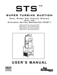
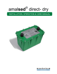
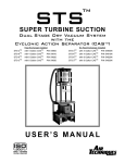
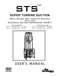
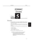
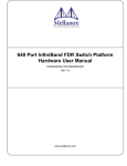
Dry Vacuum System DV5, DV7, DV10 Operation Manual Revision 02.02 Dean Dental Systems LLC 888-665-8607 www.deandentalsystems.com DV_ Dry Vacuum System Instruction manual, rev 02 Page 2 of 9 TABLE OF CONTENTS A) Safety Statement ............................................................................ pg B) Introduction .................................................................................... pg 1. Congratulations ......................................................................... pg 2. Warranty ................................................................................... pg 3. Service ..................................................................................... pg C) System Description ......................................................................... pg 1. Key Component Identification ....................................................pg 2. How it works ............................................................................. pg 3. Product Specifications ................................................................ pg D) Installation ...................................................................................... pg 1. Site Requirements.......................................................................pg 2. Equipment Specifications............................................................pg E) Operation ........................................................................................pg F) Maintenance ................................................................................... pg G) Troubleshooting ............................................................................... pg 3 4 4 4 4 5 5 6 6 6 7 7 8 8 9 Appendix 1. Dimensional Drawing ........................................................... pg 2. Installation Details................................................................. pg 3. Wiring Diagram ................................................................... pg 10 11 12 RECORD INFORMATION HERE: Model: __________________________ Serial Number:____________________ Date of Installation: ________________ Installed by: ______________________ Phone Number:____________________ Dean Dental Systems www.deandentalsystems.com 888-665-8607 [email protected] DV_ Dry Vacuum System Instruction manual, rev 02 Page 3 of 9 A. PRACTICE SAFETY Remember, Safety First! This cannot be over emphasised — practice “good” safety habits at all times and follow your company safety policies when installing, operating or servicing any equipment. To avoid injury to yourself, others or damage to the equipment, adhere to your company’s and industry safety practices. 1. Keep hands, tools, loose clothing, neckties, jewelry, long hair or other items that could get caught, away from all moving or rotating parts. 2. Read all equipment installation instructions prior to initiating installation and/or operation. 3. Employ qualified technicians, contractors, and/or licensed electrician(s) for installation, maintenance and servicing of all Dean Dental System DV blowers and associated equipment. Provisions should be made to have the owners manual readily available to the operator and maintenance personnel. If for any reason any part of the manual becomes illegible or the manual is lost, have it replaced immediately. The owners manual should be read periodically to refresh one’s memory. It may prevent a serious or fatal accident. • Never use a flammable or toxic solvent for cleaning the air filter or any parts. • Make a general overall inspection of the unit daily and correct any unsafe conditions. • Never play with the Vacuum System. Reckless behavior of any kind involving suction can cause serious personal injury. • Periodically check for proper operation. - Any alterations to the Vacuum System must have prior factory approval. Dean Dental Systems www.deandentalsystems.com 888-665-8607 [email protected] DV_ Dry Vacuum System Instruction manual, rev 02 Page 4 of 9 B. Introduction B.1. Congratulations! Congratulations on the purchase of your new DV Dual Stage Dry Vacuum System. The DV is a dry vacuum pump that produces high-volume air flow with multiple users online. The DV is a dry vacuum pump which is designed for use in a dental facility. The integrated Separator tank will ensure that no liquids or foams enter the vacuum pump. The Variable Speed Driven vacuum, with a highly reliable industrial motor can be depended upon to start every time. Your DV vacuum system with integral separator tank is easily installed and maintained. This manual provides operation, installation, and maintenance instructions for the support of the DV Dry Vacuum System without a heat exchanger. Review and follow the guidelines included in this User Manual to ensure that the system provides the highest level of service. B.2. Warranty The DV_ is warranted to be free from defects in material and workmanship from the date of installation for a period as follows: (See warranty Form for details) • • Standard Warranty: 2 years (24 months) on all components. Extended Warranty: 3 years (36 months) on all pumps, motors, and housings. Any item returned to our factory through an authorized distributor, will be repaired or replaced at our option at no charge provided that our inspection shall indicate it to have been defective. Dealer labor, shipping and handling charges are not covered by this warranty. This warranty does not apply to damage due to shipping, misuse, careless handling or repairs by other than authorized service personnel. Warranty is void if equipment is installed or serviced by other than dealer service personnel authorized by Dean Dental Systems. Dean Dental Systems is not liable for indirect or consequential damages or loss of any nature in connection with this equipment. This warranty is in lieu of all other warranties expressed or implied. No representative or person is authorized to assume for us any liability in connection with the sale of our equipment. B.3. Service Your Authorized Distributor / Service Center: Dean Dental Systems www.deandentalsystems.com 888-665-8607 [email protected] DV_ Dry Vacuum System Instruction manual, rev 02 Page 5 of 9 C. System Description The Dry Vacuum System is a variable speed vacuum pump with integral separator tank and control panel allowing fully automated operation while reducing electrical consumption. Operation is free from water or oil. Dean Dental Systems www.deandentalsystems.com 888-665-8607 [email protected] DV_ Dry Vacuum System Instruction manual, rev 02 Page 6 of 9 C.1. How it Works The Vacuum Motor is controlled by a vacuum sensor in the separator tank. The speed of the Motor will increase / decrease to maintain the pre-set vacuum level. Liquid is removed from the air stream, and collected in the separator tank until a drain cycle. C.2. Sizing Guidelines Choosing the correct size DV to meet practice depends on the number of air users and the anticipated air demand. To assure optimum operation, the demands should not exceed the number of air handpiece users shown below. Each chart lists the number of simultaneous High Volume Evacuators (HVEs) and Saliva Ejectors (SEs) that can be used in specific DV systems. D. Installation This dry vacuum unit should only be installed by qualified personnel. Should any questions arise during the installation, call Dean Dental Technical Support between the hours of 8:00 a.m. to 5:00 p.m. (Eastern Standard Time). Place the dry vacuum in a clean, dry, well ventilated area, on a solid, level surface. Be sure that adequate ventilation is available and install an exhaust fan. Ambient temperature in the equipment room should be within the temperature range of 40 degrees Fahrenheit minimum to 100 degrees Fahrenheit maximum. 1) Check the shipping carton for damage. This could detect damage to the unit which might otherwise be overlooked. Remove cardboard shipping carton. 2) Remove the Vacuum from its shipping carton. Inspect the unit for damage. Dry vacuums are shipped banded to a pallet. This pallet is intended for shipping only and should be discarded. 3) Inventory your hook-up kit. Check its contents against the inventory sheet included. These items will be used in the remaining steps. 4) Make the necessary exhaust vent connections. (WARNING: Exhaust must be vented with a metallic pipe for the first 10 feet) 5) Connect the main vacuum line. Connect flexible 2.5” hose to the side of seperator tank. 6) Connect remote control 18/2 jacketed cable to the remote terminals. 7) Connect line voltage (via safety switch if required by local code). Refer to the wiring diagram. 8) Turn on the Vacuum. Check the pump(s) for leaks and the vacuum level. Dean Dental Systems www.deandentalsystems.com 888-665-8607 [email protected] DV_ Dry Vacuum System Instruction manual, rev 02 Page 7 of 9 D.1. Site Requirements and Specifications Dean Dental Systems www.deandentalsystems.com 888-665-8607 [email protected] DV_ Dry Vacuum System Instruction manual, rev 02 Page 8 of 9 E. Operation The DV_ may be turned “ON/OFF” from the switch or a single, convenient location within the dental office using a Remote Control Panel. Remote wiring must be done by a licensed electrician in accordance with local codes. The vacuum level is factory preset at 8 in Hg (inches of mercury). This is the reading on the gauge when all HVE’s and SE’s are CLOSED. If this setting needs to be adjusted contact your dealer to readjust the setting. The unit is capable of running continuously. To conserve electricity, the system may be turned off when not in use. Do NOT run/stop the DV_ Dry Vacuum System by turning the main power ON/OFF. Run/stop via remote switch, or Local On/Off Switch. If you still need to run/stop the DV_ Dry Vacuum System by turning power ON/OFF, it is recommended to do so only ONCE per hour. The integrated separation tank has been designed to collect the fluids evacuated during a normal operating day. If an excessive amount of fluids are collected, the float switch in the separator will stop the vacuum in order for the tank to automatically drain. This process takes approximately 30 seconds. Vacuum will automatically re-start after the drain cycle. Perform the daily maintenance procedures to Clean Vacuum Lines and Washout Tank. Turn the power OFF at the end of the day. This will drain collected liquids in the CAS separation tank. F. Maintenance Weekly Service 1. Flush the main vacuum lines with a NON-FOAMING dental vacuum cleanser. Follow the cleanser manufacturers instructions. Flush the entire vacuum piping system (all operatories) weekly. Use a NON-FOAMING cleanser. It is extremely important that the cleaner used cannot and will not foam. Foam will get sucked into the vacuum producer and will cause damage over time. If the Vacuum can not induce adequate air flow because of a blockage in the vacuum piping system, liquids and solids will not evacuate. Contact Technical Support for further details on maintaining your vacuum piping system. 2. Open Separator top and rinse the inside with water. 3. Visually inspect Vacuum for leakage. Ensure that all hoses and connections are tight. Annual Service 1. Replace filter element inside separator tank every year or as needed. Dean Dental Systems www.deandentalsystems.com 888-665-8607 [email protected] DV_ Dry Vacuum System Instruction manual, rev 02 Page 9 of 9 G. Troubleshooting Problem Possible Cause Possible Solution Motor Running, No Suction Leak Kinked Suction Hose Stuck Drain Valve (Open) Piping Leak Check Check / Replace if Necessary Check, Clean as necessary Contact Plumber Motor Not Running, Hourmeter On Check LCD Display for Error See Error code in attached VFD Manual Motor Not Running, Hourmeter Off Check Power Check LCD display for Error Circuit Breaker / Fuse, Reset/Replace Contact Electrician To Access the LCD Display (on the VFD), remove the control panel by grasping the handle, and pull towards you and up. The panel is held in place by 2 screws at the top. Dean Dental Systems www.deandentalsystems.com 888-665-8607 [email protected] SHEET 1 of 1 INLET 49" DRAIN EXHAUST 1" 1 18 2 " 1 1 2 " 19" 17" Stainless Steel Adjustable Feet (4) 1 16 2 " PROPRIETARY AND CONFIDENTIAL THE INFORMATION CONTAINED IN THIS DRAWING IS THE SOLE PROPERTY OF DEAN DENTAL SYSTEMS. ANY REPRODUCTION IN PART OR AS A WHOLE WITHOUT THE WRITTEN PERMISSION OF DEAN DENTAL SYSTEMS IS PROHIBITED. DV6 Dental DRY Vacuum Package 3-8 Users DENTAL SYSTEMS www.deandentalsystems.com SHEET 1 of 1 Installation Details, DV6, DV9 PVC from Operatories 1.5" Minimum, 2" Recommended (Consult Vacuum Piping Guidelines) 4' x 2.5" ID Hose with ends Provided Fused Disconnect or Other, per local code. By Electrician 6' Electrical Cord Provided 1.5" PVC Drain SLoped Away 2" Exhaust Metal Pipe If over 10', increase to 3" Must be vented outside Per NFPA99 and Local Code Friday, October 14, 2011 12:26:20 PM PROPRIETARY AND CONFIDENTIAL THE INFORMATION CONTAINED IN THIS DRAWING IS THE SOLE PROPERTY OF DEAN DENTAL SYSTEMS. ANY REPRODUCTION IN PART OR AS A WHOLE WITHOUT THE WRITTEN PERMISSION OF DEAN DENTAL SYSTEMS IS PROHIBITED. Installation Details 2 DENTAL SYSTEMS www.deandentalsystems.com PROPRIETARY AND CONFIDENTIAL THE INFORMATION CONTAINED IN THIS DRAWING IS THE SOLE PROPERTY OF DEAN DENTAL SYSTEMS. ANY REPRODUCTION IN PART OR AS A WHOLE WITHOUT THE WRITTEN PERMISSION OF DEAN DENTAL SYSTEMS IS PROHIBITED. Friday, January 20, 2012 2:50:15 PM A2 +V HC S2 S1 Float Switch SIMPLEX VACUUM PACKAGE WIRING DIAGRAM BLACK RED Blue Blue White 24VDC Control Circuit Connection Terminals On Delta Variable Frequency Drive Shielded Cable to Vacuum Transducer (Grey) Hour Meter Blue Remote Switch By Others. 24VDC Remote Off On Switch Green (GND) Black White Motor S/L2 T/L3 www.deandentalsystems.com DENTAL SYSTEMS W/T3 V/T2 U/T1 Model V1000 Yaskawa Variable Frequency Drive R/L1 White Fused Disconnect or Circuit Breaker by Others. Per Local Code. Must Consult a Licensed Electrician. 6' Power Cord Red Disconnect ALL POWER and Wait 10 Minutes for Electrical Discharge BEFORE servicing Components. Black Warning - Electrical hazard is present. Removing the Control Panel Cover exposes you to dangerous voltage and risk of electrical shock. Do not leave the panel off while you are operating the Vacuum System. Green GND