1
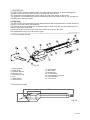
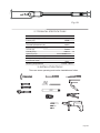
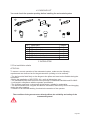
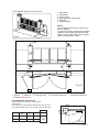
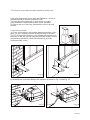
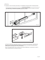
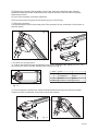
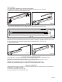
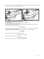
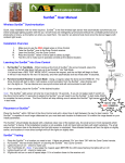
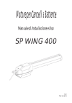
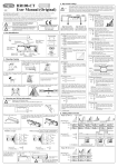
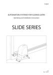
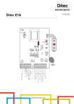
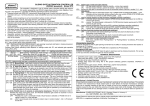
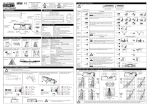
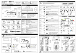
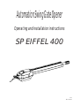
Automation Swing Gate Opener
Operating and installation instructions
SP EIFFEL 400
V1.0
Rev 08/2012
CONTENTS
0) GENERAL SAFETY REGULATIONS
.......................................................Page 02
1) DESCRIPTION..............................................................................................Page 03
2) TECHNICAL SPECIFICATIONS ................................................................Page 04
3) INSTALLATION TOOLS
4) COMPONENTS
.............................................................Page 04
..................................................................................Page 05
5) INSTALLATION ..........................................................................................Page 05
6) TESTING THE AUTOMATED SYSTEM
...........................................Page 10
7) MANUAL OPERATION .................................................................................Page 10
8) MAINTENANCE
9) REPAIRS
.......................................................................................Page 11
..........................................................................................Page 11
10) AVAILABLE ACCESSORIES
..................................................................Page 11
11) SPECIAL APPLICATION
..................................................................Page 11
Page 01
IMPORTANT NOTICE FOR THE INSTALLER
GENERAL SAFETY REGULATIONS
1) ATTENTION! To ensure the safety of people, it's important that you read all the
following instructions. Incorrect installation or incorrect use of the product could
cause serious harm to people.
2) Carefully read the instructions before beginning to install the product.
3) Do not leave packing materials (plastic, polystyrene, etc) within reach of children
as such materials are potential sources of danger
4) Store these instructions for future reference
5) This product was designed and build strictly for the use indicated in this
documentation. Any other use, not expressly indicated here, could compromise the
good condition/operation of the product and/or be a source of danger.
6) We decline all liability caused by improper use or use other than that for which the
automation swing gate opener was intended.
7) Do not install the equipment in an explosive atmosphere; the presence of
inflammable gas or fumes is a serious danger to safety.
8) The mechanical parts must conform with standards EN12604 and EN12605.
9) We are not responsible for failure to observe Good Technique in the construction
of the closing elements to be motorized, or for any deformation that may occur during
use.
10) The installation must conform to standards EN12453 and EN12445. The safety
level of the automated system must be C+D.
11) Before attempting any job on the system, cut out electrical power.
12) The main power supply of the automated system must be fitted with an all-pole
switch with contact opening distance of 3mm or greater. Use a 6A thermal breaker
with all-pole circuit break is recommended.
13) Make sure that the earthing system is perfectly constructed, and connect metal
parts of the means of the closure to it.
14) The safety device (EN12978 standard) protects from any danger are as against
mechanical movement. Risks, such as crushing, dragging and shearing.
15) Use of least one indicator-light is recommended for every system, as well as a
warning sign adequately secured to the frame structure, in addition to the devices
mentioned at point 14.
16) We decline all liability as concerns safety and efficient operation of the automated
system, if system components not produced by us are used.
17) For maintenance, strictly use original parts by us.
18) Do not in any way modify the components of the automated system.
19) The installer shall supply all information concerning manual operation of the
system in case of na emergency, and shall hand over to the user the warnings
handbook supplied with the product.
20) Do not allow children or adult to stay near the product while it is operating.
21) Keep remote controls or other pulse generators away from children to prevent the
automated system from being activated involuntarily.
22) Transit through the leaves is allowed only when the gate is fully open.
23) The user must not attempt any kind of repair or direct action whatever and
contact qualified personnel only.
Page 02
1. DESCRIPTION :
The SP EIFFEL 400 automated system for swing gates comprises an electromechanical
operator which drives the gate leaves by means of a worm screw.
The operators are equipped with a limit switch to control the stroke of the motor.
The operator is irreversible and locks mechanically when the motor is not in use, therefore a
lock does not need to be fitted.
ATTENTION:
The SP EIFFEL 400 automated system was designed and manufactured to control access of
vehicles. Avoid any other use whatever.
The motors must be installed at a minimum height of 20cm from the ground surface and not
interfere with the mobile parts.
Command pulses must be given from sites where you can see the gate
Use transmitters only if you can see the gate.
1.1 Structure Description:
6
Fig. 01
1. Rear bracket
2. Rear fitting
3. Release device
4. Electric wire
5. Aluminium body
6. Arm
7. Limit Switch
8. Worm screw
9. Long screw
10. Steel tube
11. Bronze nut
12. Frontal fitting
13. Limit Switch protection
14. Front bracket
15. Front cover
1.2 Dimensions (mm)
1010
160
250
Fig. 02
Page 03
2. TECHNICAL SPECIFICATIONS
TECHNICAL SPECIFICATIONS
SP EIFFEL 400
Power supply (V)
230V, 50Hz
Power (W)
Current (A)
Thermal protection (ºC)
Capacitor (uF)
200W
0.8A
120ºC
12μF 400V
Thrust (N)
Travel (mm)
Speed (cm/s)
Max Leaf dimension (m)
Usage frequency at 20ºC
1000N
400mm
1.6cm/sec
4.5m
30%
Protection class
Working temperature
IP54
>-20ºC, <65ºC
3. INSTALLATION TOOLS
There are some operating tools before installation as follow:
Page 04
70
48
118
Fig. 03
4. PACKING LIST
You must check the operator packing before installing the automated system
1
2
3
4
5
6
Nº
1
2
3
4
5
6
Descrição
Motor
Rear bracket
Front bracket
Key
Rear bracket fasteners
Front bracket fasteners
Quant.
2
2
2
2
2
2
5. INSTALLATION
5.1 Pre-installation checks
ATTENTION:
To ensure a correct operation of the automated system, make sure the following
requirements are observed as for the gate structure (existing or to be realized):
- The leaf must be fixed firmly on the hinges to the pillars and must not be flexible during the
movement
- Before the installation of SP EIFFEL 400, verify all dimensions, etc.
- The mechanical parts must conform to the provision of standards EN12604 and En12605.
- Leaf length in compliance with the operator specification.
- The 2 leaves must have a robust and rigid structure, suitable for automation
- The leaves should have a regular and uniform movement, without any friction and dragging
during the entire opening.
- Presence of an efficient earthing for electrical connection of the operator
The condition of the gate structure directly affects the reliability and safety of the
automated system!
Page 05
5.2 STANDARD INSTALLATION LAYOUT
1. Operators
2. Photocells
3. Logic board
4. Key-operated push-button
5. Receiver
6. Flashing lamp
NOTA:
Use suitable tubes and/or hoses to lay
electric cables;
To avoid any kind of interference always
separate low-voltage accessories and
control cables from 230V power supply
cable using separate tubes.
Fig. 05
2
3
1
4
6
5
Fig. 06
1. Motors 2. Antenna
6. Stopper (Mandatory)
3. Flashing lamp
4. Photocells (external)
5. Photocells (internal)
5.3 Installation dimensions
Determine the fitting position of the operator.
ATTENTION:
Check with care if the distance between the open leaf and
any obstacles (wall, fence, etc.) is higher than the operator.
Stroke
W
X
Y
Z
95º
1390
150
200
400
120º
1390
200
150
400
w
Fig. 07
Page 06
5.3.1 General rules to determine the installation dimensions:
If the pillar dimensions do not allow the installation, a hole on
the pillar should be created (example Fig.8).
The hole should be dimension in such a way to enable
easy installation, rotation and release device operation.
To help on the cut of the pillar, decrease the size of the wall
bracket.
5.4 Preliminary checks
1) Fix the rear bracket in the position determined before. If the
pillar is in iron, carefully weld the bracket directly to the pillar
(Fig.10). If the pillar in masonry, use suitable accessories to fix
the motor to the wall (fig.09) using the provided screws. During
the fastening operations, check if the bracket is perfectly
horizontal using a level.
Fig. 08
Fig. 09
Fig. 10
2) Assemble the rear brack fitting to the operator as shown in Fig. 11 and Fig. 12.
Fig. 11
Fig. 12
Page 07
ATTENTION:
The operator can be moved by hand only if it is installed on the gate and in released position
3) Assemble the front bracket as shown in Fig.14, a hexagonal seat is located in the lower
part of the fitting to make the assembling operations easier.
Fig. 13
Fig. 14
4) Close the leaf and, keeping the operator in a perfect horizontal position, determine the
fastening point. Close the leaf and, keeping the operator in a perfect horizontal position,
determine the fastening point of the front bracket.
Note: if the gate structure does not allow a fix bracket fastening it is necessary to create a
sturdy supporting base in the gate structure.
Page 08
5) Release the operator and manually check if the gate can completely open without
hindrances and stop at the mechanical travel stop as well as if the leaf moves regularly
without any friction.
6) Carry out necessary corrective measures.
Note: we recommend to grease all the fastening pins of the fittings.
5.5 Wiring the operator
A terminal board is fitted in the lower part of the operator for the connection of the motor, or
the limit switch
Fig. 15
Fig. 16
5.5.1 Motor wiring operations:
1) 1) Move the terminal cover and bottom cover, fit the supplied cable gland (Fig. 15 e 16).
2) Connect the motor and the earthing with reference to Fig.17.
Pos.
1
2
3
4
Cor
Azul
Castanho
Preto
Amarelo / Verde
Comum
Fase
Fase
Fio terra
Fig. 17
3) The limit switch is wired in the same terminal board where the motor wiring has been
carried out. After connected, close all the cover with screws.
Fig. 19
Fig. 18
Page 09
5.6 Limit Switch
The limit switch adjustment is carried out as follows:
1) Loosen front cover screws of the front cap and remove the cover (Fig. 20).
2) Move the cover of the limit switch (Fig. 21).
Fig. 21
Fig. 20
3) Loosen the fastening screw of the limit switch
4) Move the limit switch to the desired position and lock the screw (Fig. 22).
Fig. 22
5) Perform a pair of test cycles to check the correct position of the limit switch. If the
adjustment of the limit needs to be carried out again, repeat the operation starting from point
3.
6) After adjusting the limit switch, place back it's protection (Fig. 23 e Fig. 24).
7) Tighten the screws.
Fig. 23
Fig. 24
6. TESTING THE AUTOMATED SYSTEM
Carefully check operating efficiency of the automated system and of all accessories
connected to it, paying special attention to the safety devices.
Hand the "User's Guide" to the final user to get him with the Maintenance sheet.
Explain correct operation and use of the automated system to the user.
Indicate the potentially dangerous areas of the automated system to user.
7. MANUAL OPERATION
If the automated system needs to be moved manually due to a power lack or to an operator
malfunction, proceed as follows:
1) Open the protective cap (Fig. 25)
2) IInsert the key and turn it 90º (Fig. 26)
Page 10
Note: To move the operator in manual operation, insert the key and rotate it 90º degrees clockwise
to unlock the motor and turn off the power supply.
Fig. 25
Fig. 26
7.1 To restore normal operating conditions, proceed as follows:
1) Close the gate;
2) Turn the release system 90º in the opposite direction of the arrow.
3) Remove key and close protection cover.
4) Power up the system and perform 1 movement in order to check the correct restoring of
every function of the automated system.
8. MAINTENANCE
To ensure trouble-free operation and a constant safety level, an overall check of the system
should be carried out every 6 months.
A form for recording operations has been included in the "User's Guide" booklet.
9. REPAIRS
For any repairs, contact an authorized repair center.
10. AVAILABLE ACCESSORIES
Refer to catalogue for available accessories.
11. SPECIAL APPLICATIONS
There is no special application other than the described use.
Page 11