1
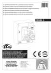
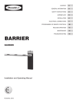
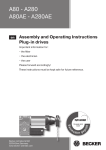
A100 5E A100AE en Assembly and Operating Instructions Sectional door drives Important information for: • Fitters • Electricians • Users Please forward accordingly! These instructions must be kept safe for future reference. Becker-Antriebe GmbH 35764 Sinn/Germany www.becker-antriebe.com Assembly and Operating Instructions Table of contents Introduction................................................................................................................................................................. 2 Warranty...................................................................................................................................................................... 2 Intended use............................................................................................................................................................... 2 Safety instructions....................................................................................................................................................... 3 Product overview and dimensions................................................................................................................................. 4 Installation................................................................................................................................................................... 4 Emergency manual operation........................................................................................................................................ 5 Voltage switching......................................................................................................................................................... 7 Electric connection to the control unit and connection diagram........................................................................................ 8 Checking the running direction.....................................................................................................................................11 Setting the door limit positions.....................................................................................................................................11 Maintenance............................................................................................................................................................. 12 Technical data........................................................................................................................................................... 13 Declaration of incorporation........................................................................................................................................ 14 Introduction The drives A100 5E and A100AE are quality products with many features and advantages. Please observe these Assembly and Operating Instructions when installing and setting the unit. Warranty Structural modifications and incorrect installation which are not in accordance with these and our other instructions can result in serious injuries, e.g., crushing of limbs. Therefore, structural modifications may only be carried out with our prior approval and strictly in accordance with our instructions, particularly the information contained in these Assembly and Operating Instructions. Any further processing of the products which does not comply with their intended use is not permitted. The end product manufacturer and fitter must ensure adherence to all the relevant current statutory, official and, in particular, EMC regulations during utilisation of our products, especially with regard to end product manufacture, installation and customer advice. Intended use The plug-in drives A100 5E and A100AE are designed solely for indoor use for the operation of sectional doors, where the inherent weight is counterweighted by springs or a counterweight, as well as for special applications (subject to approval from BeckerAntriebe GmbH). The plug-in drive must not be used in potentially explosive areas. If the drives are to be used externally, special connection cables are required; PVC connection cables must be placed in a protective conduit. The plug-in drive A100AE may only be operated in connection with a suitable control unit. This control unit must be able to evaluate the single-turn absolute value encoder in AE drives from Becker-Antriebe. Any use for other purposes or for purposes beyond the above constitutes improper use. Other applications (e.g., roller doors, vertical lift gates, hoisting devices, awnings, winders), uses and modifications are not permitted in order to protect the safety of the users and others since these actions can impair the system’s safety and carry the risk of personal injury and property damage. Becker-Antriebe does not accept liability for damages or injury arising from such actions. Always observe the information in these instructions when operating or repairing the system. Becker-Antriebe does not accept liability for damages or injury resulting from improper actions. 2 Safety instructions The following safety instructions and warnings are intended to avert hazards and to prevent property damage and personal injury. Please keep these instructions in a safe place. • • • • • • • • • • • • • • • Caution Denotes a potentially hazardous situation. If this is not avoided, injuries may result. Warning Denotes a potentially hazardous situation. If this is not avoided, the product or something in its vicinity may be damaged. Note Denotes user tips and other useful information. Important safety instructions. Caution! Failure to observe these instructions can lead to serious injuries. Follow the safety instructions contained in EN 12453, EN 12445 and BGR 232. Work on the electrical installation, the electrical or electronic systems and units may only be carried out by a qualified electrician. Assembly may only be carried out by a trained and authorised specialist. Before using for the first time, the door system must be inspected by an expert to ensure that it is in a safe condition. Stop and disconnect the door system from the mains power supply when maintenance and cleaning is being performed either on the system itself or in the immediate vicinity. Always ensure adherence to the pertinent national accident prevention regulations. Suitable protective clothing must be worn when installing the drive. When electrical or electronic equipment and units are operated, certain components are live. Physical injuries or damage to property can result in the event of unauthorised interventions or failure to heed warnings. Always ensure compliance with all applicable standards and regulations for electrical installation. Only use spare parts, tools and accessory devices which have been approved by the drive manufacturer. Unapproved third-party products or modifications to the system and its accessories represent a risk to your safety and the safety of others. This means that the use of unapproved third-party products, or modifications which have not been agreed with or approved by us, are prohibited. We do not accept liability for damages or injury arising from such actions. The limits given in the technical data must not be exceeded. When installing the drive at a height of less than 2.50 m, the drive must be covered as contact with the motor could result in burns. An adequate clearance distance must be maintained between the drive and combustible materials. When the safety limit switches are open, the control unit used must switch the drive off: • With A100 5E, the safety limit switches are S1F, S2F, S3F, S4F • With A100AE, the safety limit switches are S3F, S4F The door leaves must be secured against accidentally coming out of the guides by using fixed stops. The door system must be protected against falling. • In the case of drives for sectional doors and indirectly operated door systems, a suitable mechanism must be provided by the customer (external mechanism to catch the door or prevent it from rolling down) in order to reliably prevent the leaves/door from falling down in the event of failure of the load-bearing medium (e.g., cables or chains). • In the case of drives with a light chain (LK) or crank handle (HK), it must be ensured that the torque on the drive is less than the static holding torque stated in the technical data should the spring fracture or counterweight fail. If this is not the case, when using these drives the door must be prevented from falling down through installation of a spring fracture or anti-drop device. 3 Assembly and Operating Instructions Product overview and dimensions All dimensions in mm. Drives with a crank handle (HK) Drives with a light chain (LK) Hole pattern M 8 (10 tief) 27,6 Ø 85 6,35 JS9 Ø 25,4 Installation Caution During installation of the drive, access to the danger zone must be blocked off. The drive must be properly mounted on a vibration reducing mounting or torque supporting plate (in accordance with the output of the drive), with adequate stability. Direct mounted drives for door systems have to be fixed with 4 screws M8 (8.8) and have to be mounted with a shock absorbing bracket. Drives for indirect door systems are to be fixed with 4 screws each on both sides but do not require a shock absorbing bracket. The maximum distance from the drive to the toothing of the chain wheel is not to exceed 50 mm. The bolting torque of the fixing screws has to be 20 Nm minimum at a screw-in depth of 10 mm but is not to exceed 25 Nm. Failure to observe this may result in damage to the product or objects in the immediate vicinity. Only the supplied feather key must be used with these drives. After fastening the drive, the feather key must be secured from moving using the screws supplied. 4 Once the sectional door has been mounted and properly counterweighted, the door must be counterweighted in every position. The correct counterweight is manually adjusted by opening and closing the door. When installing the drive, always ensure that the drive is protected against soiling (e.g., drilling dust). Before mounting the sectional door drive on the door shaft, the latter must be lubricated in the drive area. Feather key for 1" tubular shaft Feather key for 1" solid shaft Emergency manual operation Emergency manual operation is only intended for commissioning the drive, maintenance work and emergency operation in order to open or close the door in the event of a short-term power failure. Emergency manual operation is solely intended for manual operation. Warning Before emergency manual operation is used, the door system must be disconnected from the power supply. Emergency manual operation (HK) is only allowed with the motor turned off, via hand crank, and can only be carried out by the service technician or instructed personnel. Emergency manual operation is not intended for long-term use (e.g., from commissioning of the drive to continuous power supply). Doors with counterweights must be set in such a way that they are fully counterweighted in all positions. If the door is not counterweighted properly, the manual force required is increased and the service life of the emergency manual operation mechanism is reduced. Note (applies to A100 5E) The door must not be moved beyond the limit positions as otherwise a safety limit switch (S1F/S2F) is activated. If activated, electrical operation of the door system is only possible when the safety limit switch (S1F/S2F) is “released” via emergency manual operation. 2 different systems are available for emergency manual operation: • Crank handle (HK) • Light chain (LK) Note For each type of emergency manual override system, an appropriate sign (as per EN60335-2-103) must be permanently placed in the vicinity of the corresponding operating element describing how it is to be used. Templates for this sign can be found in the Internet at www.becker-antriebe.com. 5 Assembly and Operating Instructions Crank handle (HK) First remove the cover. For emergency manual operation, the crank handle is inserted in the motor shaft. The crank handle must firstly be snapped onto the motor shaft by applying slight pressure (1) and turned carefully (2) in order to enable proper emergency manual operation with the crank handle. The door can then be opened or closed with the crank handle by turning whilst applying slight pressure. In order to prevent electrical operation of the door system during emergency manual operation, the safety switch S3F is opened upon insertion of the crank handle. Caution Following operation, the crank handle must be completely removed again as this may otherwise result in physical injuries and damage to property. Warning Once the crank handle has been removed the cover must be refitted in order to maintain the drive's protection type. Light chain (LK) Note Drives with a light chain (LK) can be installed horizontally and, with an additional chain reverse unit, also vertically. Installation of the chain wheel with integrated chain guard. Installation of the chain wheel with integrated chain guard Attach the chain wheel with integrated chain guard so that the side with the sticker faces the drive. Fix the chain guard using a flat washer, spring washer and screw. Insertion of the chain Turn the chain guard so the openings face upwards. Take one end of the chain and insert this into the left opening of the chain guard (1). Ensure that the chain is correctly positioned in the guide. Then turn the chain casing (2) to the right until you are able to pull out the end of the chain in the other opening. Connection of the chain ends Before connecting the ends of the chain using the chain lock it must be ensured that the chain is not twisted. The chain lock must be fastened carefully. 6 Operation Note In order to prevent repeated coupling and decoupling of the emergency manual operation mechanism, the chain must be kept taut during operation. The door can be opened and closed manually by pulling the respective side of the chain vertically. In order to prevent electrical operation of the door system during emergency manual operation, the safety switch S3F is activated when the chain is pulled. After operation ensure that the chain hangs "freely" again so that the safety switch SF3 is released, thus enabling electrical operation. Voltage switching Caution Before voltage switching, the drive must be safely disconnected from the mains. The drives can be operated on a 3~ 400 V ( star connection) or 3~ 230 V ( delivered pre-wired for operation on a 3~ 400 V network. Voltage switching for A100 5E For operation on a 3~ 230 V network, the drive must be switched from 1. 2. 3. 4. delta connection) network. The drives are star connection to delta connection: Loosen and remove the terminal on the " starpoint" (stranded wires: brown, red and black). Clamp the brown stranded wire to the U terminal (green stranded wire). Clamp the red stranded wire to the V terminal (blue stranded wire). Clamp the black stranded wire to the W terminal (yellow stranded wire). 3~230 V 3~400V U = green V = blue brown red black W = yellow = starpoint 3~ 400 V system U = green - brown V = blue - red W = yellow - black 3~ 230 V system TP TP U V W U V W 7 Assembly and Operating Instructions Voltage switching for A100AE For operation on a 3~ 230 V network, the adapter with Item no. 4822 200 203 0 must be used. This is connected between the motor plug with the coloured wires and the plug with wires 1, 2 and 3 of the connecting cable. Motor plug 3~230 V 3~230 V Adapter Plug connecting cable 3~230 V 3~400 V Electric connection to the control unit and connection diagram Caution The electric connection may only be carried out by a qualified electrician! Please observe the information on the control unit to be used and the applicable EN standards! When carrying out any connection work, always ensure the door system is safely disconnected from the mains by removing the plug/switching off the main switch. Always ensure compliance with the technical data of the drive. The limits given in the technical data must not be exceeded. In particular, the on-site fuse protection of the door system, to be carried out by the customer, must comply with the technical data! When laying the protective conductor, it must be ensured that the protective conductor connection (earth) is disconnected last if the cable is pulled out unintentionally, e.g., by bundling the individual black wires of the connecting cable together to form a loop and fixing this with a cable tie. The individual wires must not be in contact with the gear wheels/cams of the limit switching when the housing cover is closed. Ensure that the connecting cable is routed in such a way that it is not in contact with the drive. 8 Electric connection to the control unit and connection diagram for A100 5E To connect the drive to the control unit, only use an original 12-core connecting cable, which has been approved by the manufacturer. The connecting cable is plug-in. In order to ensure strain relief and the protection type, the cable gland must not be undone. The plug is fitted with reverse polarity protection and clicks audibly into place. The yellow/green protective conductor wire must be connected to the designated push-on connector . Make sure that it engages firmly. 1 2 3 4 S4F S1F S3F S2F S5 5 S6 6 TP S7 7 8 9 10 S1F S2F S3F S4F S3F S2F S1F - - - - Safety limit switch OPEN - yellow Safety limit switch CLOSE - yellow Safety limit switch HK/LK Thermal switch 11 12 12 S4F UVW S5 S6 S5 S6 S7 TP S7 - - - Operational limit switch OPEN - grey Operational limit switch CLOSE - black Functional limit switch - orange U V W • Install the individual wires of the connecting cable to the right of the central dome of the housing as shown in the diagram. • Install the protective conductor (gn/ge) below the black connecting cables. • Secure the connecting cable to the internal motor cables using the supplied cable tie. 9 Assembly and Operating Instructions Electric connection to the control unit and connection diagram for A100AE 3~230 V 3~230 V To connect the drive to the control unit, only use original 12-core connecting cables, which have been approved by the manufacturer. The connecting cable is plug-in. In order to ensure strain relief and the protection type, the cable gland must not be undone. The plugs feature reverse polarity protection and click audibly into place. The yellow/green protective conductor wire must be connected to the designated push-on connector . Make sure that it engages firmly. AE�WU AE�S80 3~400 V 3~230 V Absolute value encoder electrical interface: Plugs (1-6) 1 - Safety chain input 2 - RS485 B 3 - GND 4 - RS485 A 5 - Safety chain output 6 - 7..18 V DC Terminals (7-12 wired by manufacturer) 7/8 9/10 11/12 - S4F thermoswitch - S3F safety limit switch HK/LK - Jumper (possible connection point for external safety elements) • Install the individual wires of the connecting cable to the right of the central dome of the housing as shown in the diagram. • Install the protective conductor (green/yellow) below the black connecting cables. • Secure the connecting cable to the internal motor cables using the supplied cable tie. 10 Checking the running direction The direction of drive rotation depends on how the three mains phases are connected to the control unit and must be checked first. Proceed as follows: • Move the door into the semi-opened position using the emergency manual operation function. • Insert the mains plug of the control unit into the socket or switch the main switch of the control unit on. • Check that the control unit is in dead-man mode. • Use the OPEN and CLOSE buttons to verify whether the running direction of the door corresponds to the buttons pressed. If the running direction of the door does not correspond with the button commands, change the direction of rotation as described in the Assembly and Operating Instructions for the control unit. Then check the running direction again. Setting the door limit positions Setting the limit switch for A100 5E The drive comes with 5 cam operated end switches as standard. All cams have 12 lock-in positions for quick adjustment. Check that the control unit is in dead-man mode. Proceed as follows to set the limit switch: 1. Turn all 5 cams out of the movement range of the door. 2. Use the "DOWN" button of the control unit to move the door to just before the lower limit position. 3. Rotate the black cam S6 "CLOSE" on its shaft until the precision set screw is within easy reach. Now use the precision set screw (slotted) to accurately set the cam in such a way that it activates the switch. Move the door slightly up and down again until the end switch stops the door. Fine tune the setting as necessary. 4. Now move the door to just before the upper limit position. 5. Now set the grey cam S5 "OPEN" as for point 3. 6. Now set the yellow safety cams S1F "UP" and S2F "DOWN" to lag both operational limit switches S5 "OPEN" and S6 "CLOSE". 7. The functional cam S7 (orange) can be set accordingly if required. 8. The limit switches are now set. Carry out a test run to check the set limit positions. Note If the orange functional cam S7 is used as a pre-limit switch for functional switch-off of the safety edge of the door, then it must switch a maximum of 5 cm above the floor; EN12453 and EN12445. Replace the housing cover on the limit switching system. Make sure that the seal and the lining groove are clean and that the cover is properly positioned. Tighten the screws carefully. Setting the limit switch for A100AE The drives are equipped with an absolute value encoder with which the control unit recognises the door’s limit positions. Warning The absolute value encoder cannot be set in the drive. The door limit positions are set directly in the control unit. Follow the Assembly and Operating Instructions for the control unit. When you close the housing cover of the limit switching system, make sure that the seal and the lining groove are clean and that the cover is properly positioned. Tighten the screws carefully. 11 Assembly and Operating Instructions Maintenance Warning The door system must be regularly checked by an expert to ensure that it is in safe working order. The door manufacturer stipulates the frequency of maintenance and checks according to national regulations and the frequency of use. Counterweight: The counterweight/spring tension must be checked. The sectional door should be counterweighted in every position. Note the door's operating instructions. The following checks must be performed on the drive: 1. Fastenings: All fastening screws, including the screws to secure the torque bracket, must be checked to ensure they are in good condition and fastened securely. 2. Safety limit switches: The functionality and switch-off point of the safety limit switches S1F, S2F and S3F must be checked. Follow the relevant assembly and operating instructions for the door control unit. The safety limit switches must be checked for continuity as per the connecting diagram. Re S1F / OPEN (applies to A100 5E) Open to the upper limit position. Using the emergency manual operation function, keep opening up to the point where no damage occurs. The safety switch S1F must be checked as per the connecting diagram. There must be no continuity. Re S2F / CLOSED (applies to A100 5E) Close to the lower limit position. Using the emergency manual operation function continue closing until the load-bearing medium (e. g., cables or chains) for suspending takes the complete weight of the door sections. It must be ensured that the cables do not fall from the cable drum. The safety switch S2F must be checked as per the connecting diagram. There must be no continuity. Re S3F (applies to all HK and LK drives) Before inspecting the safety switch S3F, the door system must be disconnected from the mains. Insert the crank handle (HK) in the motor shaft and turn through at least one revolution and hold the position or pull the light chain (LK) and keep it taut. The safety switch S3F must be checked as per the connecting diagram. There must be no continuity. 3. Gears: The gears are lubricated for life and maintenance-free. 4. Toothed belt 1. Check that the toothed belt has sufficient preliminary tension. 2. Carry out a visual check of the toothed belt along the complete travel distance of the door. The toothed belt must show no signs of wear. TP Toothed belt 12 U V W Technical data Type Drive torque Drive speed Diameter of hollow shaft Operating voltage Frequency Nominal current Performance factor Insulation material class Thermoswitch Mode Protection type Limit switch range Static holding torque On-site fuse protection Permissible ambient operating temperature Weight *) (approx.) Unit T n U f I cos j S3 IP Nm min-1 mm V Hz A °C % Revolutions Nm A100 5E A100AE 100 25 25.4 3~ 230/400 50 4.6 / 2.6 0.71 H 170 40 54 13 450 3 x 10 A T °C -20 to +40 kg 10 *) With version LK the weight increases by approx. 0.5 kg. Deviations are possible in structurally identical drives or special drives. The information on the type plate always applies. Subject to technical changes without notice 13 Assembly and Operating Instructions Declaration of incorporation 14 15 2349 300 002 0g 08/12