1
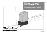
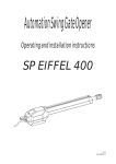
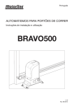
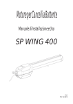
English
AUTOMATION SYSTEMS FOR SLIDING GATES
Operating and installation instructions
BRAVO500
v1.0
Rev 08/2012
INDEX
1) General Safety Regulations ............................................................................... pág. 01
2) Description ......................................................................................................... pág. 02
3) Technical Specifications .................................................................................... pág. 03
4) System Description ........................................................................................... pág. 03
5) Accessories ....................................................................................................... pág. 04
6) Installation Tools ................................................................................................ pág. 04
7) Installation .......................................................................................................... pág. 05
8) Maintenance ...................................................................................................... pág. 10
9) Repairs .............................................................................................................. pág. 10
1) GENERAL SAFETY REGULATIONS
1) ATTENTION! To ensure the safety of people, it is important that you read all the following
instructions.
Incorrect installation or incorrect use of the product could cause serious harm to people.
2) Carefully read the instructions before beginning to install the product.
3) Do not leave packing materials (plastic, polystyrene, etc.) within reach of children as such
materials
are potential sources of danger.
4) Store these instructions for future reference.
5) This product was designed and built strictly for the use indicated in this documentation. Any
other
use, not expressly indicated here, could compromise the good condition/operation of the
product
and/or be a source of danger.
6) Manufacturer / distributor decline all liability caused by improper use or use other than that for
which
the automated system was intended.
7) Do not install the equipment in an explosive atmosphere: the presence of inflammable gas or
fumes
is a serious danger to safety.
8) The mechanical parts must conform to the provisions of Standards EN 12604 and EN12605.
For
non-EU countries, to obtain an adequate level of safety, the Standards mentioned above must be
observed, in addition to national legal regulations.
9) We are not responsible for failure to observe Good Technique in the construction of the closing
elements to be motorised, or for any deformation that may occur during use.
10) The installation must conform to Standards EN 12453 and EN 12445.
11) Before attempting any job on the system, cut electrical power.
12) Make sure that the earthing system is perfectly constructed, and connect metal parts of the
means
of the closure to it.
13) The automated system force control. Nevertheless, its tripping threshold must be checked as
specified in the Standards indicated at point 10.
14) The safety devices (EN 12978 standard) protect any danger areas against mechanical
movement
risks, such as crushing, dragging, and shearing.
15) Use of at least one indicator-light is recommended for every system, as well as a warning sign
adequately secured to the frame structure.
16) Manufacturer / distributor decline all liability as concerns safety and efficient operation of the
automated system, if system components not produced by them.
17) For maintenance, strictly use original parts by us.
18) Do not in any way modify the components of the automated system.
19) The installer shall supply all information concerning manual operation of the system in case
Pág. 01
2) DESCRIPTION
Automated system for residential sliding gates with leaves up to 7m long and 500 kg in weight.
It consists of a reversing electro-mechanical gearmotor, powered by a 24V control unit.
The automated system houses a programmable electronic control board that enables setting of
function logics, work time and pause time, anti-crushing sensitivity as well as partial-opening
width.
The reversing system guarantees the gate will automatically lock when the motor is not
operating.
A release system enables the gate to be moved by hand in case of malfunction or emergency.
The automated system was designed and built for controlling sliding gates. Do not use for any
other purpose.
2.1. Description of the structure
6
7
8
15
9
1
14
2
13
11
12
3
4
5
1. Gate
2. Rack spacer
3. Protective cover
4. Foundation plate
5. Fixation screw
Fig. 01
10
6. Control box
7. Motor
8. Cover
9. Rack
10. Housing
11. Lock
12. Manual release
13. Capacitor
14. Screw
15. Limit switch plate
2.2. Dimensions (mm)
186,4
14
5
1
319,5
27
36
255
9
32
144
183
Fig. 02
Fig. 03
Pág. 02
3) TECHNICAL SPECIFICATIONS
Technical specifications of the automated operator:
Power supply (V)
Rated absorbed power (W)
Max speed (m/sec)
Force
Working time
Noise
Thermal reset
Operating temperature (ºC)
Protection class
Thermal protection (ºC)
Leaf max weight (Kg)
Leaf max length (m)
Working frequency
Capacitor
230V , 50Hz
280W
0.16m/s
1200N
15min
≤ 56dB
2min per complete cycle
> -45ºC to < 65ºC
IP44
120ºC
500Kg
7m
25%
8uF
4) DESCRIPTION OF THE SYSTEM
4
1 2
3 9
6
8
5
12
8
9
7
11
10
Fig. 04
1. Motor
2. Control board
3. Receiver
4. Left limit switch plate
5. Right limit switch plate
6. Rack
7. Key selector
8. Photocell column
9. Safety photocells
10. Antenna
11. Warning light
12. Safety edge
Pág. 03
Note:
1) To lay down electric cables, use rigid and/or flexible adequate tubes.
2) To avoid any kind of interference, always separate low voltage connection cables from
AC230V power
cables.
3) The description of system is standard system, but we did not provide all parts.
If you want system accessories, please contact us.
5) ACCESSORIES
You must check the operator packing before installing the automated system.
Fig. 05
No
1
2
3
4
5
Name
Motor
Left limit switch plate
Right limit switch plate
Screw DIN912 M5x10
Foundation plate
Qtd
1
1
1
4
1
No
6
7
8
9
Name
Ground Fixation screw
Motor Fixation screw
Key
User Manual
Qtd
4
4
2
1
6) INSTALLATION TOOLS
Fig. 06
Pág. 04
7) INSTALATION
7.1. Preliminary checks
To ensure safety and an efficiently operating automated system, make sure the following
conditions are
applied:
- The structure of the gate must be suitable for being automated. In particular, check that the
structure is sufficiently strong and rigid, and that its dimensions and weight conform to those
indicated in the technical specifications;
- Make sure that the gate slides without any inclination;
- Make sure that the gate moves uniformly and correctly, without any irregular friction during its
entire travel;
- The soil must permit sufficient stability for the expansion plugs securing the foundation plate;
- Remove any locks and lock bolts. We advise you to have any metalwork carried out before the
automated system is installed.
7.2. Preparing the foundation plate
Fit the 4 supplied nuts, as shown in Fig. 07 and Fig. 08, in the 4 holes of the plate.
Fig. 08
58
Fig. 07
7.3. Preparing the foundation plate
a) The foundation plate must be located as shown in Fig. 9a (right closing) or Fig. 9b (left closing)
to ensure the rack and pinion match correctly.
90º
Fig. 09a
90º
Fig. 09b
Pág. 05
b) Put the foundation plate to the floor, using adequate expansion plugs and provide one or more
tubes for routing the electric cables through the plate (Fig10 and 11).
Using a level, check if the plate is perfectly horizontal.
Fig. 10
Fig. 11
7.4. Positioning the operator
Lay the electric cables to connect motor to accessories and power supply as shown in Fig. 4.
To facilitate making the connections, allow the cables to project by the required length for
connection to the control board, transformer and etc (if provided).
Position the operator on the plate, using the supplied screws as shown in Fig. 12.
Fig. 12
Pág. 06
7.5. Adjusting the operator
Adjust the distance of the operator from the gate by referring to Fig.13.
55 mm
Fig. 13
7.6. Fixing operator
Fix the operator slightly tightening the screws as shown in Fig. 14.
Fig. 14
After fixing the motor, screw cover (Fig. 15 and 16).
Fig. 15
Fig. 16
Pág. 07
After the upper-cover fixed, please install the side-cover (Fig. 17).
Fig. 17
7.7. Releasing the operator
Prepare the operator for manual operating mode as described below:
Insert supplied key on the lock, turn it clockwise 90°, pull and open the manual release.
Fig. 18
Fig. 19
After opened the manual release, you can operate the door manually.
7.8. Installing the rack
Fig. 20
- Prepare the rack to be applied.
Putting
these spacers in all holes of the rack in
order to be completely secure.
a) Manually put the gate leaf in the closed position.
b) Positioning the first rack part to be bolted, supported on the pinion and with help of the level
and
clamping tool, keep it horizontally leveled.
Pág. 08
c) Move the gate to manually back and forth, to ensure that the gear rack is properly seated on
the pinion and movement occurs smoothly.
d) Set the rack in the gate. (Fig. 21) .To ensure a correct fixation, can go slowly moving the gate
and setting the gate spacers always near the pinion.
e) Pull another element of the rack above, using a piece of additional rack teeth to synchronize
the two elements (Fig. 22).
f ) Use a level again to make sure that rack is perfectly level.
g) Manually move the gate and carry out the operations of attachment such as with the first
element, proceeding up to the end of the gate.
NOTE: This motor can work with all types of racks.
Fig. 21
Fig. 22
When installing nylon rack, make the application following the same steps described in the
previous
paragraphs.
Start by placing the gate in the closed position, support the first meter of rack pinion on the
engine and
keeping it level horizontally, screw the first screw.
Go opening the gate and tightening the remaining bolts.
Continue adding more rack parts and repeating the same steps to complete the installation.
NOTES:
- Make sure that, during the gate travel, all the rack elements mesh correctly with the pinion.
- Do not, on any occasion, weld the rack elements either to the spacers. For fixing these, use
screws and
washers like in the Fig.20.
- Do not use grease or other lubricants between rack and pinion.
Pág. 09
7.9. Installing limit switch plate
a) After having rack nstalled, take the gate back to the closed position and position the limit
swicth plate
on the rack. In this closed position, the plate should trigger the limit switch of the motor.
b) Tighten the screws DIN912 M5x12 included in the pack, until it touches the rack, squeezing it.
c) Move the gate to the open position and repeat the same process for the other limit switch
plate.
DIN912
M5x10
Fig. 23
Fig. 24
8) MAINTENANCE
Carry out the following operations at least every 6 months.
- Check the efficiency of the release system.
- Check the efficiency of the safety devices and accessories.
9) REPAIRS
For any repairs, pls contact the authorised repair centers.
Pág. 10