1
3
C
Installation &
Maintenance
Tuesday, November 30, 20047
C3 Installation and Maintenance
I-CUBE
page 2
Table of Contents
1.
PURPOSE & SCOPE ............................................................................... 4
2.
REFERENCED DOCUMENTS ................................................................. 4
3.
OVERVIEW .............................................................................................. 4
3.1.
4.
5.
Product description ............................................................................................................. 4
C3 MAJOR ELEMENTS ........................................................................... 5
4.1.
Block Diagram ..................................................................................................................... 5
4.2.
Hardware ............................................................................................................................. 6
4.3.
Software ............................................................................................................................... 6
4.4.
Modes ................................................................................................................................... 6
MECHANICAL INSTALLATION............................................................... 7
5.1.
Overview .............................................................................................................................. 7
5.2.
C3 Unit Mechanical installation.......................................................................................... 8
5.2.1.
Height of C3............................................................................................................. 8
5.2.2.
Distance from barrier – Front Plate......................................................................... 9
5.2.3.
Distance from barrier – Rear Plate ........................................................................ 10
5.2.4.
Distance from barrier – Dual Camera per lane ("Stereo")..................................... 11
5.3.
6.
7.
Detector installation .......................................................................................................... 12
ELECTRICAL INSTALLATION .............................................................. 13
6.1.
The connection box............................................................................................................ 13
6.2.
Temporary Terminal connection ..................................................................................... 14
SOFTWARE INSTALLATION ................................................................ 15
7.1.
Loading the Software components ................................................................................... 15
7.1.1.
Files are loaded into C3 unit ................................................................................. 15
7.1.2.
Windows based application (loaded into the PC).................................................. 15
8.
TECHNICIAN’S WORKBENCH APPLICATION .................................... 16
8.1.
Overview ............................................................................................................................ 16
8.2.
Getting started ................................................................................................................... 16
8.3.
Main Window .................................................................................................................... 17
Barry T. Dudley
[email protected]
www.I-Cube.co.za
C3 Installation and Maintenance
I-CUBE
page 3
8.4.
System test.......................................................................................................................... 17
8.4.1.
General Test .......................................................................................................... 17
8.4.2.
I/O test................................................................................................................... 18
8.4.3.
Image capturing..................................................................................................... 19
8.5.
System calibration ............................................................................................................. 19
8.6.
Software updates ............................................................................................................... 20
8.7.
Miscellaneous..................................................................................................................... 21
8.7.1.
System configuration settings................................................................................ 21
8.7.2.
Error log file.......................................................................................................... 23
8.7.3.
Gsm error log file .................................................................................................. 23
8.7.4.
Recognition format................................................................................................ 24
8.7.5.
Twb application log file ........................................................................................ 24
9.
INTERFACING THE C3 .......................................................................... 25
9.1.
Overview ............................................................................................................................ 25
9.2.
MicroTerminal................................................................................................................... 25
9.2.1.
Connection ............................................................................................................ 25
9.2.2.
Settings.................................................................................................................. 25
9.3.
GSM Terminal ................................................................................................................... 25
9.3.1.
Safety precautions for the user .............................................................................. 25
9.3.2.
Components........................................................................................................... 25
9.3.3.
Installation............................................................................................................. 26
10. TROUBLE SHOOTING .......................................................................... 27
11. SUPPORT AND MORE INFORMATION ................................................ 28
Barry T. Dudley
[email protected]
www.I-Cube.co.za
I-CUBE
C3 Installation and Maintenance
page 4
1.Purpose & Scope
This document provides installation and maintenance information on Compact Car
Controller (C
C3), a stand-alone vehicle access-control system. This document is
intended for system installers and provides all the information required installing and
operating the system.
2.Referenced Documents
2.1 C3 User Manual
2.2 Siemens M20 / M20 Terminal Technical Description
These documents are available in our home page, see last section for details.
3.Overview
3.1.Product description
C3 is a stand-alone vision-based access-control system for vehicles. It identifies the
license plate and automatically opens the gate for authorized vehicles (in the AccessControl mode) or reports on the plate number (in the Monitoring mode).
This revolutionary system is a highly integrated computer/camera/illumination unit
that performs all the functions of a License Plate Recognition (LPR) system with its
embedded Microprocessor and See/Car recognition package.
The unit is easily installed ("2 screws installation") at the entrance to a secured area
or parking lot. It automatically turns on the integrated illumination, captures the
image, locates the license plate, recognizes the registration number, compares it to an
authorization list and opens the gate if the vehicle is authorized (in the Access-Control
mode).
Authorized vehicle numbers are stored on the unit’s local database (for AccessControl). Users can change the authorization list using the cellular phone, the Internet,
a micro-terminal (keyboard and display), or via an external computer. C3 can also
transmit the recognized registration number though RS232 serial line to a printer or
display and also as an input to other systems.
This unit is a breakthrough in the LPR market which simplifies the architecture, cost
and installation requirements over existing PC-based solutions (such as our See/Lane
Windows system). The C3 unit is "PC-Less" and is more compact and easier to install
and use.
Barry T. Dudley
[email protected]
www.I-Cube.co.za
C3 Installation and Maintenance
I-CUBE
page 5
4.C3 major elements
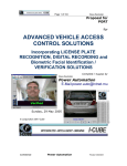
4.1. Block Diagram
The C3 access-control system architecture is illustrated in the following diagram.
The peripherals on the left side are connected via a single serial port and can be
connected only one of each.
On the right side the inputs are power supply (a DC adapter connected to the mains),
a sensor (dry-contact indicating vehicle presence, such as a loop detector). The output
is the gate relay.
Output
devices
Camera &
LPR unit
\\\\\\\\
Micro
Terminal
110-220
PC host
Serial port
Only
one
device
Power Supply
Sensor
GSM
Terminal
Gate
Remote Access via
cellular phone or
Internet
Figure 4.1: C3 Hardware block Diagram
Barry T. Dudley
[email protected]
www.I-Cube.co.za
I-CUBE
C3 Installation and Maintenance
page 6
4.2.Hardware
1. C3 - illumination/camera/LPR unit.
2. Power supply for C3 (a special 15 VDC, 110-220VAC power supply is used
which was qualified to operate with the SCH unit).
3. Vehicle detector (sensor). A standard dry-contact sensor. (can be supplied upon
request)
4. Micro-Terminal – handheld terminal (if this interface is ordered; not required
for the Monitoring mode)
5. GSM Terminal – M20 Siemens terminal (if this interface is installed)
6. PC Host - any standard PC/laptop, connected by RS232 serial communications,
used for normal operation (as an option to update the members list) or used for the
installation and maintenance.
7. Gate - the C3 output relay controls the gate's relay to open the gate for the
authorized vehicle (only required for the access control mode).
4.3.Software
1. C3 The C3 is loaded with files used to operate the system.
2. PC applications - the PC is used for installation and maintenance, and is one of
the optional interfaces, and has several applications on it.
4.4.Modes
The C3 can operate in two modes:
• Access Control - the unit opens a gate for an authorized vehicle (listed in a
local database). It can also optionally send the result via rs232232.
• Monitoring Mode - the unit just reports the recognized number via RS232
The selection of the mode is by a configuration parameter. It is pre-configured at the
factory and may be changed later.
Barry T. Dudley
[email protected]
www.I-Cube.co.za
I-CUBE
C3 Installation and Maintenance
page 7
5.Mechanical Installation
This section describes the physical installation. A single lane access-control
configuration is assumed.
5.1.Overview
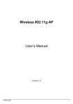
The following figure illustrates how the system is typically installed at the entrance of
a secured area. A sensor (such as a loop detector) indicates the presence of the car,
which signals the C3 unit (behind the gate's boom) to start a new recognition
sequence. The unit identifies the car and if authorized opens the gate.
Figure 5.1: a typical installation
For most secured areas the system can control the entrance only, while the exit will
be automatically opened for the vehicles exiting the secured area (by a direct
connection from the sensor to the gate). Thus a single lane access control will be
sufficient to secure the area.
Barry T. Dudley
[email protected]
www.I-Cube.co.za
I-CUBE
C3 Installation and Maintenance
page 8
5.2.C
C3 Unit Mechanical installation
This paragraph assumes that a standard 12mm lens is mounted in the unit for
European plates, or 16mm lens for USA size plates.
5.2.1.Height of C3
5.2.1.1.Typical Heights
For most installations, install the C3 unit on a pole or tripod at a recommended height
of 1.1 meters (or within 1m-1.2m).
This height optimizes the performance and positions the camera to look downwards in
order to minimize the sun effect – since most plates are mounted at a height of 0.20 to
1.25 meters.
5.2.1.2.Higher installations
The maximum height is 3 meters. In this case the camera angle should be positioned
such that the center of the vertical field of view will be looking at the trigger area. For
higher installations please consult with Hi-Tech Solutions.
5.2.1.3.Wall mounting
In case of a wall mounting, secure the unit to the wall at the same height.
5.2.1.4.Anti-Vandalism Enclosure
In case the Anti-Vandalism Enclosure is ordered, install the metal case on the floor.
Barry T. Dudley
[email protected]
www.I-Cube.co.za
C3 Installation and Maintenance
I-CUBE
page 9
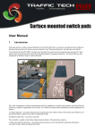
5.2.2.Distance from barrier – Front Plate
This paragraph refers to installation of the camera in the front of the vehicle.
5.2.2.1.Along the traffic lane
Install the C3 2.5 (or 2m for non-reflective plates / USA size plates) from the barrier,
in the direction of traffic, at the side (as near as possible to the lane). See the
illustration below, parameter B. This corresponds to 5.5 meters (or 4.5 meters for
non reflective plates / USA size plates) from the line of the detection of the front of
the car (parameter A).
The following diagram shows this setup (for an access control system).
BARRIER
Vehicle
L
O
O
P
Vehicle
C
B
C3
A
Figure 5.2.1: Front Installation distances (See text for explanations)
A possible problem that may be encountered during this installation is that the
barrier blocks the effective recognition view zone (This zone is the area from
the start of detection plus addition 1.5 meters). In most gates the barrier’s
height is 0.80 to 1.20 meters so this case will not occur – but in any case it
should be tested and avoided.
5.2.2.2.Side of the Traffic lane
Install the C3 as close as possible to the traffic lane, within 0.0 to 0.5 meters. See the
illustration above, parameter C. This can be constructed on both sides of the traffic
lane.
Barry T. Dudley
[email protected]
www.I-Cube.co.za
C3 Installation and Maintenance
I-CUBE
page 10
5.2.3.Distance from barrier – Rear Plate
The installation of the camera/illumination unit in the rear of the car is possible and
may occur in the following cases:
• A front installation is not possible due to traffic lane limitations (such as the
front is located in a public area where no installation is permitted)
• There are only rear plates (such as in most of the United States)
• An additional recognition is desired in order to increase the recognition
coverage (a dual camera per lane installation - which is supported and described
later)
C
C3
L
O
O
P
B
Exit line of detection
Figure 5.2.2: Rear Installation distances (See text for explanations)
The C3 unit should be installed at 4 meters from the loop detection line (parameter
B). This translates to about 9 meters or more from the front of the car since a typical
vehicle is about 4 meters.
The side distance (parameter C) in this installation is identical – 0.0 to 0.5 meters.
Barry T. Dudley
[email protected]
www.I-Cube.co.za
I-CUBE
C3 Installation and Maintenance
page 11
5.2.4.Distance from barrier – Dual Camera per lane ("Stereo")
A special setting configures the C3 to operate in dual camera per lane (also called
"Stereo" mode). In this mode 2 cameras are used to recognize the car, thus increasing
the recognition rate. The application uses special logic that takes both results. This
mode shares a single sensor per lane to initiate the recognition process.
A typical installation using this mode will be cameras looking at the front and rear
plates.
This mode is illustrated in the following illustration. The typical values are A front
= 5 meters and A rear = 9 meters.
BARRIER
L
O
O
P
C3
C3
A rear
C
A front
Figure 5.2.3: Front & Rear installation (dual cameras per lane, shared activation)
Barry T. Dudley
[email protected]
www.I-Cube.co.za
I-CUBE
C3 Installation and Maintenance
page 12
5.3.Detector installation
This paragraph assumes that the detector is magnetic-loop detector type that can be
provided by Hi-Tech Solutions. However, any standard dry-contact vehicle
sensor can suffice.
1st. Read the detector’s installation guide before installation.
2nd. Install the detector (DET) loop at about 5.5m (or 4.5m for non-reflective
plates) from the SCH, on the other side of the barrier (where the vehicle
approaches the barrier). See front-installation illustration, parameter A.
1st. The loop should be 2m wide, 1m long, 4 turns at least (see note below) placed
in the middle of the lane.
2nd. Connect the loop to the detector by twisted pair as required by the
manufacturer.
3rd. The detector’s plug connects to the I/O card (this is explained below).
4th. Detector Setup (in case of Nortech type):
1. Use channel 1
2. Freq. Set to M-L
3. Sensitivity set to D (Normal)
4. Mode set to 1 (presense)
5th. Push reset button once after power up (with no vehicle on the loop).
6th. Use normally Open contacts for output (10,11).
Note: In some installations a different loop configuration should be used in case of a
bumper to bumper line of moving cars. Please consult with us on solutions for this
case.
Barry T. Dudley
[email protected]
www.I-Cube.co.za
C3 Installation and Maintenance
I-CUBE
page 13
6.Electrical installation
6.1.The connection box
For the convenience of the installation and maintenance, a special connection box is
now designed. Temporary: the box is replaced by a screw terminal connection please refer to the drawing in the next page.
The box is shown in the following illustration (the single lane box):
Figure 5.3.1 C3 connection box (single lane)
The box has the following connection nodes:
• C3 connector (input, output) - that connects the connection box to the C3 unit
• Sensor/gate (input, output) - connects to the sensors and gate. There are 2 pair
of screws for the gate and for the sensor. Note that the input/outputs are "dry
contact" type (i.e., open or short).
• M20 Power supply - outputs power to the (optional) GSM interface (output)
• Power supply (input). - gets 15VDC from the power supply unit (which feeds
from the 100-200VAC mains).
• RS232 serial connection (input and output) - connects to the serial interfaces.
Some units may require a license plug to be connected first. Pin 9 has +5VDC
which is required for the micro-terminal.
Barry T. Dudley
[email protected]
www.I-Cube.co.za
C3 Installation and Maintenance
I-CUBE
•
page 14
Video Monitor (output) - a BNC connection for a video monitor, used for
installation.
6.2.Temporary Terminal connection
A temporary terminal connection is shown in the following drawing. It is used as a
temporary connection block until the connection box will be ready for shipments.
Note that the micro-terminal connection uses a special serial cable with pin 9 as
+5VDC.
V id eo ou t (B N C )
1 1 0 -2 2 0 V
PS 15V D C :
R ed+
B la c k -
PS
C3
G a te O u t B ro w n & B lu e
I / O c a b le ( 6 )
S e n s o r In
G r e e n & W h it e
R s2 3 2
D B 9 m a le
Barry T. Dudley
[email protected]
www.I-Cube.co.za
I-CUBE
C3 Installation and Maintenance
page 15
7.Software installation
7.1.Loading the Software components
7.1.1.Files are loaded into C3 unit
The C3 is shipped with the latest software components already installed in the
factory. These are the items:
1. Ccc.exe
- main application.
2. Ewb.exe
- test and file transfer program.
3. Gsm.exe
- GSM terminal connection program. (GSM option only)
4. Kb.exe
- Micro-Terminal connection program.
5. Ht.exe
- a program to update data base list by Windows Members.exe
application.
6. Cars.txt
- authorized members data base file. The list is updated by the
user (see the user manual).
7. Format.ini
- country-specific license plates recognition information.
8. Config.ini
- application configuration settings.
7.1.2.Windows based application (loaded into the PC)
1. Members.exe - application to update authorized members data base list.
Reference: C3 User manual.
2. Twb.exe
- technician work bench application. The application purpose is
basic testing, system calibration and C3 software updates.
Barry T. Dudley
[email protected]
www.I-Cube.co.za
C3 Installation and Maintenance
I-CUBE
page 16
8.Technician’s workbench application
8.1.Overview
Twb.exe is an application designed for authorized personal usage only. The
application purpose is system basic test, system calibration and software updates. The
application requires PC with 586 processor and at least 32 MB RAM, running
WIN95/98/Me.
The latest version is available on our support page. Please see details in the last
section of this document.
8.2.Getting started
Install C3 utilities package on host PC. You do not need to restart the PC. Connect PC
host with C3 Com port by using standard serial cable. Be sure that C3 is in an idle
state. If C3 is in a recognition process the attempt to connect will fail. Start twb.exe
application. The connection dialog will now appear.
Figure 8.2: Connection dialog
Choose Com port and press Connect button. Next time the application will show this
Com port number automatically.
Barry T. Dudley
[email protected]
www.I-Cube.co.za
I-CUBE
C3 Installation and Maintenance
page 17
8.3.Main Window
The application main window will appear, as shown below:
Figure 8.3: Main Window
8.4.System test
8.4.1.General Test
Press General test button to run system basic test. The system has to pass all checks
(big "PASS" letters are shown after some seconds). If one of tests (or more) will fail,
contact with HI-TECH Solutions technical support.
The following image shows the result of this test:
Barry T. Dudley
[email protected]
www.I-Cube.co.za
I-CUBE
C3 Installation and Maintenance
page 18
8.4.2.I/O test
Press "I/O test" button. You will see the following dialog:
When a car passes the sensor the car icon will appear on the
Dialog:
Barry T. Dudley
[email protected]
www.I-Cube.co.za
I-CUBE
C3 Installation and Maintenance
page 19
You can check right gate electrical connection by press "Open Gate" button.
You can manually set the light intensity.
8.4.3.Image capturing
8.4.3.1.Capturing an image
If "General test" finished successfully you can capture images and download them to
the PC host. Press "Capture" button. Download progress will shown in the bottom of
image area.
NOTE:
1. Image transfer is slow - done by RS232 communication. It takes from 1 minute (in
57600 baud rate) up to 4.5 minute (in 9600 baud rate), so be patient or take a coffee
break…
2. Prior to the image capture, set the illumination to a desired level.
8.4.3.2.Recognition zone
A red rectangle will appear on the image surface. This rectangle defines the active
recognition zone. You can move it by mouse dragging with the left mouse button
pressed.
You have to ensure that the car plate appears in this area from the moment the sensor
was activated, and in all the possible car positions. (See Configuration settings for
details how to update offset in C3 settings).
8.5.System calibration
This section is intentionally left open.
Barry T. Dudley
[email protected]
www.I-Cube.co.za
I-CUBE
C3 Installation and Maintenance
page 20
8.6.Software updates
To update executables files press "File transfer" button. An FTP style dialog box will
appear. The right side will contain C3 files (after pressing the "Connect" button). The
left side of the dialog is saved for new files that are downloaded to C3. Press browse
button and explorer to the directory contains new files.
Before you start transfer a file be sure that its version is the recent C3 file with the
same name. Only one file can be transfer each time.
By pressing "Delete" button you can delete one unnecessary files from the C3
memory.
NOTE: Like in the case of image transfer this can take some minutes, so be patient.
Wait for message box with message of successful finish transformation.
Barry T. Dudley
[email protected]
www.I-Cube.co.za
I-CUBE
C3 Installation and Maintenance
page 21
8.7.Miscellaneous
8.7.1.System configuration settings
Press "Config.ini" button and on the configuration dialog press "Get settings" button.
After few seconds current configuration will appear in the dialog fields.
8.7.1.1.MaxImages
The value is number of images captured for each light level.
Range: 1-3.
Default: 2.
8.7.1.2.MaxCycles
Stop condition for light levels. See LightMode for more details.
Range: 1-3.
Default: 3.
8.7.1.3.Threshold
Number of possible mistakes during comparing recognition results with numbers in
database.
Range: 0-3.
Default: 1.
8.7.1.4.LightMode
Light management.
1 - low level only (MaxCycles parameter is ignored)
2 - medium level only (MaxCycles parameter is ignored)
3 - high level only (MaxCycles parameter is ignored)
4 - light level will be changed from low to high (if MaxCycles is 2 only two levels
will
be used: low and medium)
5 - light level will be changed from high to low (if MaxCycles is 2 only two levels
will
be used: high and medium)
Recommended value for front plate installation is 5 - "high to low" ( with MaxCycles
as 3).So the system will try to make recognition with high light level, after this with
medium and after this with low. At each level the gate will open if there is a positive
recognition, so most cases the first illumination level will suffice.
Barry T. Dudley
[email protected]
www.I-Cube.co.za
I-CUBE
C3 Installation and Maintenance
page 22
8.7.1.5.MaxLanes
If C3 was supplied with more than 1 lane you can make settings for these lanes.
The default value is 1.
8.7.1.6.Monitor
Set "0" for access control mode (this is the default if the parameter does not exist), or
"1-100" for monitoring recognition grade threshold (the minimum mark for
transmitting the result; the system stops the recognition cycle when passing this
mark).
8.7.1.7.Sensor, Camera 1, Camera 2, Gate
These settings are made due to internal connections. Please do not make changes.
8.7.1.8.Send Result via COM port
Check the option if you want to send recognition results to external devices.
The baud rate of the results is 9600 and cannot be changed in current application
version.
8.7.1.9.Format
You can format resulting string:
%C - sends recognized car code.
%F - sends first name of the person if was found in database.
%L - sends last name of the person.
%D - sends date in format mm/dd/yyyy
%T - sends time in format hh:mm:ss.
%A - if the recognition plate was found in database will send text of Text1 field.
%U - sends Text2 text if the recognition car code wasn't found in database.
In addition, command characters can also be output. For example: 13h - CR (type
0x0A) or 10h - LF (type 0x0d). Each other character entered to the format string will
output as is.
Example: "0x0a0x0d %C %D" format string will be output:
(CR+LF)
1234567 03/15/2001
Barry T. Dudley
[email protected]
www.I-Cube.co.za
I-CUBE
C3 Installation and Maintenance
page 23
8.7.1.10.Image settings
Brightness.
Range: 1-255
Default:
127
Contrast.
Range: 1-127
Default:
100
Offset - offset recognition area from the top of image.
Range: 0-78
Default: 78 (= 3/4 bottom part of image is recognized)
The desired value can be measured on the captured image using the red rectangle
display.
Press "Set settings" button to send changed settings to C3.
NOTE: Copy of config.ini file is saved automatically in application directory.
8.7.1.11.Miscellaneous
1)
Press F12 key to view C3 time/date. If you want to correct the time (date),
press "Set time / date" button on the dialog. The PC host time will be sent to C3.
2)
When you exit the application, the C3 will restart and resume normal operation
in about 30 seconds.
8.7.2.Error log file
If an internal error occurs during C3 work it saves its reference in the error.log file.
Press "View Error log" button and press "Get" on the dialog. If an error log exists it
will be transferred to the Dialog window. You can save it on PC host and contact us
later.
Pressing "Delete" button will delete error.log in C3. Pressing "Clear" only empties
dialog window.
8.7.3.Gsm error log file
If the C3 system was supplied with GSM interface (Siemens M20 Terminal), specific
errors of this interface will be saved in gsm_err.log. Getting the log is the same like in
the case of C3 error log.
Barry T. Dudley
[email protected]
www.I-Cube.co.za
I-CUBE
C3 Installation and Maintenance
page 24
8.7.4.Recognition format
The purpose of the format.ini file is for recognition performance. Please make changes
in the file only after consulting with us.
8.7.5.Twb application log file
A log file is created and can be read.
The application saves a log file that contains all the operations you've done. The file
name is "twb.log". You can see the file by pressing "twb.log" button on the
application main window or open it by an editor from application directory. The file
will be empty next time you start the application.
Barry T. Dudley
[email protected]
www.I-Cube.co.za
I-CUBE
C3 Installation and Maintenance
page 25
9.Interfacing the C3
9.1.Overview
The section describes how to prepare interface devices to work with C3. For operation
details please refer to C3 User Manual.
9.2.MicroTerminal
9.2.1.Connection
A cable with six pin modular connectors and DB9 Female adapter is used to connect
with C3. The MicroTerminal does not need an external Power Supply: Pin 9 of C3
DB9 connector is used to supply 5V DC and pin 5 for Ground.
9.2.2.Settings
The MicroTerminal settings are:
• Baud rate - 9600
• Data bits - 8
• Parity - even
Please refer to supplied MicroTerminal manual how to check and change the settings.
9.3.GSM Terminal
9.3.1.Safety precautions for the user
• Users are advised not to use the device in automotive service stations.
• Users are reminded of the necessity to comply with restrictions regarding the
use of radio devices in fuel depots, chemical plants and locations where explosives
are ignited.
• As is the case with other mobile radio transmitters, operating personnel are
advised to use the device in the normal operation position only in order to ensure
optimum performance and safety.
• If your M20 Terminal, your SIM card or both are lost, notify your network
operator immediately in order to avoid misuse.
9.3.2.Components
1. M20 Siemens Terminal.
2. 3V small SIM card.
3. 9-pin serial cable for connection between C3 (PC host) and M20 Terminal.
4. Antenna cable with GSM antenna and fitting connector for connection with
M20 Terminal’s FME female antenna plug.
NOTES:
1. Power supply is supplied from the C3 connection unit.
Barry T. Dudley
[email protected]
www.I-Cube.co.za
I-CUBE
C3 Installation and Maintenance
page 26
2. SIM cards are available from different network operators. The “calling
number for 4800 Bits/s data transfer and SMS” service need be enable by local
GSM provider/user agreement.
9.3.3.Installation
Please refer to Getting started & Installation chapter of M20 Technical Description.
After the SIM card was installed some default (manufactured) settings have to be
changed. The PC host and HyperTerminal program is needed for this purpose.
The settings are:
1. Select SMS Message Format. Set text format.
Command: AT+CMGF=1 (Reference: p.94 M20 technical description)
2. Show SMS Text mode Parameters.
Command: AT+CSDH=1 (Reference: p.108 M20 technical description)
3. Set Fixed Local Rate (RS232 Baud rate). Set 9600 baud rate.
Command: AT+IPR=9600 (Reference: p.53 M20 technical description)
NOTE: After this command you have to change HyperTerminal baud rate to 9600
to continue operation.
4. Set Result Code Format mode.
Command: ATV1 (Reference: p.42 M20 technical description)
5. Enable command echo. Do not echo characters received from terminal.
Command: ATE0 (Reference:: p.38 M20 technical description)
NOTE: After this command you will not see typing characters.
6. Store current parameter to user defined profile. All above parameters must be
store in user defined profile.
Command: AT&W0 (Reference: p.45 M20 technical description)
NOTE: The user defined profile is stored in non-volatile memory.
7. If more than one GSM providers are available one of them has to be choused.
Command: AT+CSCA= ”service center address” (Reference: p.106)
8. Last parameter (service center address) must be stored to SIM card.
Command: AT+CSAS. (Reference: p.106 M20 technical description)
Stored configuration is automatically downloaded each time the system is started up.
Barry T. Dudley
[email protected]
www.I-Cube.co.za
I-CUBE
C3 Installation and Maintenance
page 27
10.Trouble Shooting
This section will provide hints on potential problems during installation.
Barry T. Dudley
[email protected]
www.I-Cube.co.za
C3 Installation and Maintenance
I-CUBE
page 28
11.Support and more Information
You can contact us for more information and assistance at:
Barry T. DUDLEY
(MBA {IT};
MSc {Image Analysis};
I-CUBE (I3 - Integrated, Intelligent, Imaging)
BSc {Brewing};
BSc Hons {Waste Technology})
LICENSE PLATE RECOGNITION AND FACIAL IDENTIFICATION SOLUTIONS
http://www.i-cube.co.za/
Cell: +27 (0) 82 562 8225
MADADENI
PH +27 (0) 31 764-3077
82 Kloof Falls Rd
Fax 031-7643077
Kloof, Durban, Kwa-Zulu Natal, 3610, South Africa E-mail: [email protected]
Quote: On the plains of hesitation lie the blackened bones of countless millions who
at the dawn of victory lay down to rest, and in resting died.
Visit our Home page http://www.i-Cube.co.za
and download the latest versions from the on-line support page. For password please contact us.
Barry T. Dudley
[email protected]
www.I-Cube.co.za