1
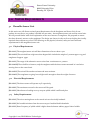
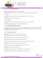
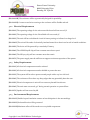
Simon Fraser University 8888 University Drive Burnaby, BC V5A 1S6 October 13th, 2011 Dr. Andrew Rawicz School of Engineering Science Simon Fraser University Burnaby BC V5A 1S6 Re: Functional Specifications for Proximity Detector for the Visually-Impaired Dear Dr. Rawicz, Please find enclosed the functional specifications for PROXIMIview Technologies’ Wearable Proximity Detector for the visually-impaired. The purpose of the device is to aid the user in avoiding obstacles via tactile and auditory feedback by utilizing an array of ultrasonic sensors mounted on sunglasses. Our system is designed to be aesthetically pleasing, and metrics such as accuracy, performance, ease of use and reliability have been important considerations. The comprehensive set of functional requirements in the enclosed document will be used extensively by our team at PROXIMIview Technologies for the implementation of the proof-of-concept device, as well as for integrating and testing purposes. It will also be used as a guideline to assess the progress of development. PROXIMIview Technologies is comprised of four talented, dynamic and motivated engineering students namely Renuka Rani, Gary Brykov, Sajith Kulasekare and Marish Lalwani. If you have any questions or concerns, please feel to contact me by phone (778-321-3761) or by e-mail ([email protected]). Thank you very much for your consideration. Yours sincerely, Renuka Rani Chief Executive Officer (CEO) PROXIMIview Technologies Ltd. Enclosed: Functional Specifications for Proximity Detector for the Visually-Impaired Copyright © 2011, PROXIMIview Technologies Simon Fraser University 8888 University Drive Burnaby, BC V5A 1S6 PROXIMIVIEW TECHNOLOGIES Functional Specifications for a Wearable Proximity Detector to Aid the Visually-Impaired Contact Person: Submitted To: Issue Date: Gary Brykov [email protected] Andrew Rawicz – ENSC 440 Mike Sjoerdsma – ENSC 305 School of Engineering Science Simon Fraser University October 13th, 2011 ENSC 440/305 | Simon Fraser University Copyright © 2011, PROXIMIview Technologies Simon Fraser University 8888 University Drive Burnaby, BC V5A 1S6 PROXIMIVIEW TEAM Copyright © 2011, PROXIMIview Technologies Renuka Rani CEO Sajith Kulasekare CTO Gary Brykov CFO Marish Lalwani COO Simon Fraser University 8888 University Drive Burnaby, BC V5A 1S6 EXECUTIVE SUMMARY Statistics have shown that out of the 836,000 Canadians 78.5% have a mild to medium severity and the rest of the 21.5% are severely visually-impaired [3]. This makes visually-impaired people very vulnerable to mishaps such as accidents. Therefore, here lies the need for assistive devices. Hence, the severely impaired people would use the assistive devices than the people with mild to medium limitations. Statistics have pointed out a very important fact which gives the relationship between the need versus availability of these assistive devices for the visually-impaired of the mild to medium and the severe categories. According to Statistics Canada, 19.6%, i.e one in every five people with a severely impaired vision demanded the need for assistive devices but said that they were not available. Although 6.1% of the mild to medium population have been proactively participating in purchasing the products available in the market, they have showed their grievances regarding the availability of such products. Another interesting fact that showed up was the cost factor of these products. 38% of the population said that the exorbitant prices of these products hindered them from using these glasses [3]. Our goal for this project is the betterment of human society and helping the needy. We aim to build a device with that acts as a proximity detector for the objects for the visually-impaired. This device would alert the user through a feedback unit composed of a vibrator and an automated voice message that would let the user know about the direction of the object relative to user’s position. We have split the project up into four stages namely design, development, integration testing the proof of concept. The development of our product will occur in two phases namely: Mounting the sensors on the sunglasses and connecting them to the control unit Developing the Control Unit which controls the sensing as the input of the sensors is fed in Therefore, this document outlines the general, physical, electrical and other functional specifications of our product as a planned approach by our company, PROXIMIview Technologies. We would ensure to address various critical issues and provide a genuine technological solution which would be robust and would not be susceptible to various common fallacies. We would diligently work in a scheduled manner and plan to finish up the final product by December 2011. Copyright © 2011, PROXIMIview Technologies i Simon Fraser University 8888 University Drive Burnaby, BC V5A 1S6 TABLE OF CONTENTS Executive Summary .................................................................................................................................................. i List of Figures .......................................................................................................................................................... iv 1.0 Introduction ...................................................................................................................................................... 1 1.1 Scope .......................................................................................................................................................... 1 1.2 Intended Audience .................................................................................................................................. 1 1.3 Classification of Requirements ............................................................................................................. 1 2.0 System Overview ............................................................................................................................................. 2 2.1 Overall System Requirements .............................................................................................................. 4 3.0 System Requirements .................................................................................................................................... 5 3.1 Wearable Sensor Unit ............................................................................................................................ 5 3.1.1 Physical Requirements ............................................................................................................... 5 3.1.2 Electrical Requirements ............................................................................................................. 5 3.1.3 Safety Requirements ................................................................................................................... 5 3.1.4 Environmental Requirements .................................................................................................. 6 3.1.5 Standards ...................................................................................................................................... 6 3.2 Control/Feedback/Power Unit............................................................................................................. 6 3.2.1 Physical Requirements ............................................................................................................... 6 3.2.2 Electrical Requirements ............................................................................................................ 7 3.2.3 Safety Requirements .................................................................................................................. 7 3.2.4 Environmental Requirements .................................................................................................. 7 3.2.5 Mechanical Requirements......................................................................................................... 8 3.2.5 Standards ...................................................................................................................................... 8 3.3 Reliability and Durability ..................................................................................................................... 8 4.0 User Interface and Documentation............................................................................................................. 9 4.1 User Interface.......................................................................................................................................... 9 4.2 Documentation ..................................................................................................................................... 10 Copyright © 2011, PROXIMIview Technologies ii Simon Fraser University 8888 University Drive Burnaby, BC V5A 1S6 5.0 System Test Plan ............................................................................................................................................ 11 5.1 Component Testing Stage .................................................................................................................... 11 5.1.1 Arduino Microcontroller ........................................................................................................... 11 5.1.2 Arduino VoiceShield .................................................................................................................. ii11 5.1.3 PING))) 28015 Ultrasonic Sensor ............................................................................................. 11 5.1.4 Mini Speaker 15mm, LilyPad Vibrator Board Control and Power Switch ........................ 11 5.2 Prototype Integration Testing Stage ................................................................................................. 11 5.2.1 Functionality/Accuracy ............................................................................................................. 11 5.2.2 Structural Strength and Durability ......................................................................................... 12 5.2.3 Safety and Comfort .................................................................................................................... 12 6.0 Conclusion ...................................................................................................................................................... 13 7.0 References ....................................................................................................................................................... 14 Copyright © 2011, PROXIMIview Technologies iii Simon Fraser University 8888 University Drive Burnaby, BC V5A 1S6 LIST OF FIGURES Figure 2.1: Ultrasonic Sensor Arrangement ........................................................................................................ 2 Figure 2.2: User Wearing the PROXIMIview device ............................................................................................3 Figure 2.3: System Block Diagram ..........................................................................................................................3 Copyright © 2011, PROXIMIview Technologies iv Simon Fraser University 8888 University Drive Burnaby, BC V5A 1S6 1.0 INTRODUCTION The Wearable Proximity Detector by PROXIMIview Technologies is an assistive device for the visuallyimpaired to aid the user in avoiding objects/obstacles. The device will utilize an array of ultrasonic sensors which will be mounted on sunglasses to inform the user when an object is a certain distance away. The feedback unit will feature both tactile and auditory elements; a vibrating unit will be used to alert the user of the relative proximity of the object – the closer the user gets to the object, the more frequent the vibrations. Auditory feedback will be composed of messages informing the user about the distance of the object, as well as some directional messages. The requirements for the Wearable Proximity Detector as proposed by PROXIMIview Technologies are outlined in the following document. 1.1 Scope This document describes the functional requirements for the Wearable Proximity Detector. It provides a detailed description of the required functionality for a proof-of-concept mode, and also gives a fair idea of the same for the production device. The requirements outlined in the document will be used by the PROXIMIview team during the design, implementation and testing of the proof-of-concept device. 1.2 Intended Audience The functional specifications document is intended to be used by members of the PROXIMIview team to track progress, requirements and developmental phases to ensure that the design is within specifications. It will also be used to compare the proof-of-concept device with the proposed design. 1.3 Classification of Requirements The following convention will be utilized throughout this document to outline different categories of functional requirements: [R#-n p] where # denotes the section number, n denotes the requirement number and p denotes the priority of the specification and can have one of the following values: I – High Priority level II – Moderate Priority Level III – Low Priority Level Copyright © 2011, PROXIMIview Technologies 1 Simon Fraser University 8888 University Drive Burnaby, BC V5A 1S6 2.0 SYSTEM OVERVIEW The PROXIMIview Wearable Proximity Detector utilizes three PING))) ultrasonic sensors mounted on a pair of sunglasses to alert the user of any obstacles at eye-level. The first sensor is mounted looking directly forward from the user’s perspective. The second sensor is mounted orthogonally to the first, facing left from the user’s perspective. The third sensor is mounted orthogonally to the first, facing right from the user’s perspective. Figure 2.1 illustrates the sensor arrangement. PING))) Sensor 1 PING))) Sensor 2 PING))) Sensor 3 Figure 2.1: Ultrasonic Sensor Arrangement The sensor wiring will be integrated into the sunglass frame and will run down into the control module. The control module contains the Arduino Uno Microcontroller unit, the Arduino VoiceShield, speaker, vibrator, and battery unit. The control module and relevant components will be contained in a robust weatherproof enclosure that is designed to be worn via a strap or kept in the user’s pocket during device operation. The enclosure is to have a simple ON/OFF switch, a 3.5 mm headphone jack, and a removable cover for battery access. Volume control for the speaker and headphones will also be included. Copyright © 2011, PROXIMIview Technologies 2 Simon Fraser University 8888 University Drive Burnaby, BC V5A 1S6 Figure 2.2 shows the positioning of the device on the user’s head. Figure 2.2: User Wearing the Device The entire system will be powered by a single rechargeable 9 volt PP3 battery, using snap connectors which allow for obvious battery polarization and prevent incorrect battery installation when being replaced by a visually-impaired person. In order to not leave the user with dying/dead batteries, a low battery indicator will also be included, again, providing vibratory and audio feedback of the battery’s state. The PROXIMIview system overview is provided in Figure 2.3. Wearable Sensor Array PING))) Sensor 1 PING))) Sensor 2 PING))) Sensor 3 Control/Feedback/Power Module Arduino Uno MCU Arduino VoiceShield Speaker Battery Unit Vibrator Figure 2.3: System Block Diagram Copyright © 2011, PROXIMIview Technologies 3 Simon Fraser University 8888 University Drive Burnaby, BC V5A 1S6 2.1 Overall System Specifications [R2.1-1 II] The system must operate over a temperature range of -40°C to 50°C. [R2.1-2 II] The system must operate over a relative humidity range of 5% to 95%. [R2.1-3 I] The system must not cause harmful interference. [R2.1-4 II] The system must accept any interference received, including interference that may cause undesired operation. [R2.1-5 I] The system must be easily operable by a visually-impaired/blind user. [R2.1-6 I] The device will have a portable power source [R2.1-7 I] The proof-of-concept must meet the applicable testing standards of CSA Class B consumer electronics appliances, as required by Industry Canada to qualify for sale and distribution in Canada. [R2.1-8 I] The proof-of-concept must comply with all CSA C22.2 No. 1010-92 safety standards. [R2.1-9 I] The PROXIMIview Technologies device support must comply with CSA customer service standard for people with disabilities of Class B No. 480-02. [R2.1-10 I] All electrical parts and wiring shall conform to the specifications outlined in C22.2 No. 203.1-94 (Manufactured Wiring Products) and C22.2 No. 0.3-01 (Test Methods for Electrical Wires and Cables). Copyright © 2011, PROXIMIview Technologies 4 Simon Fraser University 8888 University Drive Burnaby, BC V5A 1S6 3.0 SYSTEM REQUIREMENTS 3.1 Wearable Sensor Unit In this section we will discuss various System Requirements for the Sunglasses and Sensor Unit for our product. As seen above, our product is divided into two units - the sunglasses/sensor unit and the control unit. We will proceed further with a brief explanation of the use of sensors on sunglasses. We proposed to mount the three ultrasonic sensors on the sunglasses. The design was chosen in order to focus on helping the visuallyimpaired detect objects at eye-level. The following are the physical, electrical, safety and environmental requirements for the sunglasses/sensor unit: 3.1.1 Physical Requirements [R3.1.1-1 I] The sunglass/sensor unit will have dimensions of 10cm x 8cm x 4cm. [R3.1.1-2 II] The unit shall not weigh more than 80gm which includes the weight of 3 sensors approx. 27g and sunglasses of approx. 45gm. [R3.1.1-3 I] The range of the ultrasonic sensor varies from 2 centimeters to 3 meters. [R3.1.1-4 III] There shall be no buttons, only the sunglasses with the three sensors mounted in it and wires running down to the control unit. [R3.1.1-5 II] The unit will be weather resistant and water resistant. [R3.1.1-6 II] The sunglasses are going have a high tensile strength to bear the weight of sensors. 3.1.2 Electrical Requirements [R3.1.2-1 I] The three sensors will operate at 5V respectively. [R3.1.2-2 I] The maximum current for the sensors will be 35mA. [R3.1.2-3 I] Short bursts of reading at every 200μs at 40kHz which is sufficiently fast. 3.1.3 Safety Requirements [R3.1.3-1 I] The wires running down to the control unit are electrically insulated. [R3.1.3-2 I] No harmful emissions from the sensors as per Canadian Health Standards. [R3.1.3-3 I] Burst Frequency of 40kHz which is higher than the human auditory upper limit of 20kHz. Copyright © 2011, PROXIMIview Technologies 5 Simon Fraser University 8888 University Drive Burnaby, BC V5A 1S6 3.1.4 Environmental Requirements [R3.1.4-1 III] Sunglasses are made from recyclable material. [R3.1.4-2 II] Use of digital components which would ensure no harmful substances released in the environment. [R3.1.4-3 II] Double Layered insulation ensures no heat dissipation in the surroundings. [R3.1.4-4 II] No harmful noise will be generated. 3.1.5 Standards [R3.1.5-1 III] The sensors shall conform to CAN/CSA-C22.2 NO. 61010-2-032-04(R09) [2]. [R3.1.5-2 III] The sunglasses/sensors shall conform to ANSI standards. 3.2 Control/Feedback/Power Unit This unit is composed of the Arduino Uno Board, the VoiceShield, the battery unit, speaker and vibrator, all of which will be contained within a well-insulated enclosure. The following are the physical, electrical, safety and environmental requirements for the unit: 3.2.1 Physical Requirements [R3.2.1-1 I] The box will not exceed 12cm x 10cm x 6cm in size. [R3.2.1-2 I] The weight of the enclosure will be no more than 500gm. [R3.2.1-3 II] The finalized device will be pocket sized and easy to carry. [R3.2.1-4 III] The enclosure will be aesthetically pleasing to the eye. [R3.2.1-5 I] All internal components will be protected and insulated from static and shock. [R3.2.1-6 I] The enclosure will be made of an insulating material. [R3.2.1-7 II] The enclosure will be durable and resistant to cracks/breaks. [R3.2.1-8 III] The enclosure will be black in color. [R3.2.1-9 III] The enclosure will have the PROXIMIview Technologies logo on it. [R3.2.1-10 II] The placement of the controls/buttons will be user-friendly. Copyright © 2011, PROXIMIview Technologies 6 Simon Fraser University 8888 University Drive Burnaby, BC V5A 1S6 [R3.2.1-11 III] The enclosure will be ergonomically designed for portability. [R3.2.1-12 II] Connectors and wires running to the enclosure will be flexible and soft. 3.2.2 Electrical Requirements [R3.2.2-1 I] The operating voltage for the microcontroller board will not exceed 9V. [R3.2.2-2 I] The operating voltage for the VoiceShield will not exceed 5V. [R3.2.2-3 I] The unit will have a dedicated circuit for battery testing to indicate low charge level. [R3.2.2-4 II] The unit will be made of electrically insulated materials so that it can be safe in humid conditions. [R3.2.2-5 I] The device will be powered by a standard 9V battery. [R3.2.2-6 I] The ATMEGA328P chip will not consume more than 0.25mA. [R3.2.2-6 I] The ISD4003 chip will not consume more than 20mA. [R3.2.2-7 I] The power supply must be sufficient to support continuous operation of the system. 3.2.3 Safety Requirements [R3.2.3-1 I] All electrical components must be enclosed. [R3.2.3-2 I] All electrical components must be shielded to protect the user. [R3.2.3-3 I] The system will be safe to operate around people with a very low risk level. [R3.2.3-4 I] The enclosure will not have any sharp edges that may potentially harm the user. [R3.2.3-5 I] Electrical components in unit will not cause any harmful interference. [R3.2.3-6 I] The unit must not exceed 35°C during normal operation or system failure. [R3.2.3-7 I] Speaker will not exceed 65 dB. 3.2.3 Environmental Requirements [R3.2.3-1 II] Double Layered insulation ensures no heat dissipation in the surroundings. [R3.2.3-2 II] No harmful noise will be generated. [R3.2.3-3 III] Maximum effort will be made to use recyclable components. Copyright © 2011, PROXIMIview Technologies 7 Simon Fraser University 8888 University Drive Burnaby, BC V5A 1S6 3.2.5 Mechanical Requirements [R3.2.5-1 I] Operation buttons will be placed apart from each other. [R3.2.5-2 I] Power button will be placed away from the operation buttons. [R3.2.5-3 I] Power button will not be easy to press/toggle. 3.2.6 Standards [R3.2.6-1 III] The control unit will conform to CAN/CSA-C22.2 NO. 61010-2-032-04(R09) [2]. [R3.2.6-2 III] The control unit will conform to ANSI standards. 3.3 Reliability and Durability [R3.3-1 I] The assistive device will be water proof and will provide assistance under all weather conditions. [R3.3-2 I] Sensor will accurately detect objects under all lighting conditions. [R3.3-3 I] Sanity checks shall be programmed into the Arduino Uno to provide feedback when sensors malfunction. [R3.3-4 I] Battery level indicator will provide audio feedback to the user when battery level goes below 7V. [R3.3-5 II] For the ATMEGA328P chip projected data retention failure rate is less that 1PPM over 20 years at years at 85°C or 100 years at 25°C. [1] [R3.3-6 I] The ISD4003 voice chip will be functional on a temperature range of -65°C to 150°C. [5] [R3.3-7 I] PING))) sensor will function in a temperature range of +32 to +158 °F (0 to +70 °C). [4] [R3.3-8 II] 9V rechargeable battery will be used to supply power to the device, which will have built-in circuitry to control overcharging and over-discharging of the battery. Copyright © 2011, PROXIMIview Technologies 8 Simon Fraser University 8888 University Drive Burnaby, BC V5A 1S6 4.0 USER INTERFACE AND DOCUMENTATION 4.1 User Interface The PROXIMIview device aims to simplify user operation as much as possible. Because use of the device is intended for visually-impaired individuals, successful operation of the device must be possible without any visual cues. The following specifications outline the physical user interface of the PROXIMIview wearable proximity detector. [R4.1-1 I] The system start-up/shutdown switch shall be easily accessed using sense of touch alone. [R4.1-2 I] The system start-up/shutdown switch shall not be prone to accidental toggling during device operation. [R4.1-3 I] The device volume controls shall be easily controlled using sense of touch alone. [R4.1-4 I] The device should not impede the user’s mobility any more than a regular pair of sunglasses. [R4.1-5 II] The use of preferred feedback (auditory or tactile or both) shall be chosen by the user via an unambiguous mechanism. [R4.1-6 I] The auditory feedback shall be clear and accurate upon detection of obstacles. [R4.1-7 III] The user shall be notified via a preferred feedback method regarding the battery’s 50%, 25%, 10% and 5% charge status. [R4.1-8 I] All options and features of the system shall be fully accessible by a blind individual. Copyright © 2011, PROXIMIview Technologies 9 Simon Fraser University 8888 University Drive Burnaby, BC V5A 1S6 4.2 Documentation The PROXIMIview wearable proximity detector proof-of concept system training and documentation will be focused on educating a visually-impaired user on how to properly and effectively utilize the device to increase the user’s perception of the surroundings. Included with the wearable proximity detector, the PROXIMIview user will receive a 5 to 10 page manual with instructions written instructions written in English. A Braille version of the user’s manual shall also be included, along with an audio CD containing operating instructions that can be played back on a disc player or computer. The written user’s manual, the Braille user’s manual, and the audio user’s manual will all contain identical content which is broken down into the following sections. 1. 2. 3. 4. 5. 6. 7. 8. 9. Product Introduction Safety Information Initial Setup and Calibration Operation Instructions Feedback Interpretation Recharging/Replacing the Battery Troubleshooting Technical Information Legal Copyright © 2011, PROXIMIview Technologies 10 Simon Fraser University 8888 University Drive Burnaby, BC V5A 1S6 5.0 SYSTEM TEST PLAN PROXIMIview Technologies is focused on providing assistive devices for the visually-impaired which combines functionality, accuracy, aesthetic appeal and comfort. To provide products of the highest caliber, our products will be rigorously tested from the smallest component to the final product. Testing will be carried out in two different stages, namely, Component Testing Stage and Prototype integration Testing stage. 5.1 Component Testing Stage All components involved in the final product will be meticulously tested for functionality and accuracy before the integration stage. 5.1.1 Arduino Microcontroller A thorough test will be carried out to check the functionality of the voltage supply (7-10V) and the functionality of the Digital input/output pins (40mA per pin) under different temperature conditions. 5.1.2 Arduino VoiceShield VoiceShield will be mounted on top of the Arduino Uno, and will be powered by the same voltage supply. Feedback response time will be measured and efforts will be made to minimize response time in different temperatures. 5.1.3 PING))) 28015 Ultrasonic Sensor PING))) sensor will be connected to the Arduino Uno and accuracy measurement will be made to figure out functional specifications of the sensor such as detection range and the wide angle range. Functionality of sensor will be tested between 0-70°C which is the operational temperature of the sensor. 5.1.4 Mini Speaker 15mm, LilyPad Vibrator Board control and power switch Using a multimeter, component functionality will be tested for different temperature settings. 5.2 Prototype Integration Testing Stage 5.2.1 Functionality / Accuracy Integrated prototype will be tested on a hall way, where the visually-impaired test subject (wearing the assistive device) will try to maneuver around eye level objects. Accuracy measurements of object detection and feedback time will be made and improved through efficient programming of the Arduino board. A number of functionality tests will be carried out: Functionality of all sensors (audio feedback when sensors malfunction) Copyright © 2011, PROXIMIview Technologies 11 Simon Fraser University 8888 University Drive Burnaby, BC V5A 1S6 Operation under all mentioned scenarios Function of the vibrator module Battery level audio feedback Power Consumption Power requirement calculations will be carried out and a tentative battery life measurement will be provided to supply a voltage above 7V to the Arduino board (as the outputs of the Arduino will be unstable if the voltage is less than 7V). Circuit will be improved to operate efficiently, providing a longer battery life. 5.2.2 Structural Strength and Durability Number of drop tests, pressure tests and temperature tests will be carried out to analyze the structural integrity of the device. Weather testing will be carried out to ensure functionality of the assistive device under numerous weather conditions. 5.2.3 Safety and Comfort Testing will be carried out to provide high safety and comfort levels for the visually-impaired. Further testing will be carried out to improve aesthetic appeal of the device. Copyright © 2011, PROXIMIview Technologies 12 Simon Fraser University 8888 University Drive Burnaby, BC V5A 1S6 6.0 CONCLUSION The functional specifications demonstrate the capabilities and the requirements of our product. We at PROXIMIview Technologies Ltd. will strive hard to follow and abide by the requirements to bring out a robust product. As mentioned above the development of our final product would take place in two phases namely: the sunglasses/sensor unit and the main Control Unit. The prototype development is well underway and we are expected to have a complete and working prototype by December 15th 2011. Copyright © 2011, PROXIMIview Technologies 13 Simon Fraser University 8888 University Drive Burnaby, BC V5A 1S6 7.0 REFERENCES [1] ATMEL(n.d.). ATmega328P[Online]. Available: http://www.atmel.com/dyn/products/product_docs.asp?category_id=163&family_id=607&subfamily_id=760&part_i d=4198, [Oct. 13, 2011]. [2] CSA Standards. Internet: http://shop.csa.ca/en/canada/measurement-control-and-signalingapparatus/cancsa-c222-no-61010-2-032-04r09/invt/27021072004/, [Oct. 13, 2011]. [3] “Facts on Seeing Limitations.” Internet: http://www.statcan.gc.ca/pub/89-628-x/2009013/fs-fi/fs-fi-eng.htm, [Oct. 13, 2011]. [4] PARALLAX INC.(n.d.). PING))) Ultrasonic Sensor[Online]. Available: http://www.parallax.com/tabid/768/ProductID/92/Default.aspx, [Oct. 13, 2011]. [5] Winbond Electronics Corp.(2004). ISD 4003 Series[Online]. Available: http://hackedgadgets.com/wpcontent/2/Winbond-ISD4003-05MS.pdf, [Oct. 13, 2011]. Copyright © 2011, PROXIMIview Technologies 14