1
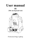
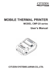
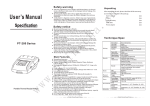
USER GUIDE T58P/S Thermal Printer SHENZHEN ICOD DIGITAL CO., LTD. 1 DECLARE § This product belongs to A grade, maybe it will cause radio disturbance at natural enviroment, In such circumstances, needs that the user takes practicable measures for it. COPYRIGHT This document made by 2007 Eidition: 1.0 <2007.06> 2 Security Information In order to use your printer in effectiveness and security, Please obey the following rules. →Before Use ● In order to hold the ture usage method, Before using printer, please read this user’s manual particularly. ● Please put this《User’s Manual》on the convenient position, In order to take out reading and solving problems at any moment. →Notices In Security If neglect the following notice matters, incorrect use may be bring damage. NOTICE ◇ If occurred paper jams, make sure turining off button as the first step, waiting for ten seconds, in order to cool down the print head, and then clearing away the paper. ◇ Please don’t set this product in the humid or dusty enviroment. ◇ No pressing, No dumping. Roller Paper ◇ Make sure to use the specific roller paper which fit for this manual. ◇ Don’t be used the roller paper which the end be felted on the paper axes, Or, the printer can’t detect the end of roller paper exactly, may be could bring damage to printer; Aslo can’t choose the roller paper which without paper axes, Or, may be when printing to the end, Paper jams occurred because of the paper barycentre is not enough. 3 TABLE OF CONTENTS Chapter Ⅰ Introduction.................................................................................................................... 6 1.1 Technique Specification........................................................................................................ 6 1.2Printing Paper......................................................................................................................... 6 1.3Printing Character.................................................................................................................. 6 1.4Interface Form........................................................................................................................ 6 1.5 Control Command................................................................................................................. 7 1.6Power and Operating Environment Request......................................................................... 7 1.7 Dimension and Weigh........................................................................................................ 7 Chapter Ⅱ Installation and Operation.................................................................................. 8 2.1 Printer Dimension................................................................................................................. 8 2.2 Control Board........................................................................................................................ 8 2.3 Indicator light and key operation.......................................................................................... 8 2.4 Installing paper...................................................................................................................... 9 2.5 Interface connection............................................................................................................ 10 2.5.1 Serial interface connection.......................................................................................10 2.5.2 Parellel interface connection.................................................................................... 11 2.5.3 Cash drawer interface.............................................................................................. 12 2.6 Clear print head................................................................................................................... 13 Chapter Ⅲ Malfunction Exclusion.......................................................................................... 14 4.1 Command Illustration......................................................................................................... 14 Chapter Ⅳ Printing Table.........................................................................................................15 4.1 Command Illustration......................................................................................................... 15 4.2 Printing command............................................................................................................... 15 4.2.1 Printing command.................................................................................................... 15 LF.............................................................................................................................. 15 ESC J n...................................................................................................................... 16 4.2.2 Setting command for line spacing................................................................................... 16 ESC 2........................................................................................................................ 16 ESC 3 n..................................................................................................................... 16 4.2.3 Character printing command............................................................................................16 ESC ! n...................................................................................................................... 16 ESC SO..................................................................................................................... 17 ESC DC4................................................................................................................... 17 ESC % n.................................................................................................................... 17 ESC & s n m............................................................................................................. 18 4.2.4 Special Control Command............................................................................................... 18 ESC c 5 n...................................................................................................................18 4.2.5 Graphic Printing Commands............................................................................................18 ESC * m n1 n2 d1......dk........................................................................................... 18 GS / n........................................................................................................................ 20 GS * n1 n2 d1......dk................................................................................................. 20 4.2.6 Bar code command.......................................................................................................... 21 4 GS w n.......................................................................................................................21 GS h n........................................................................................................................22 1 GS k m d1......dk NUL......................................................................................... 22 ○ 2 GS k m n d1......dn............................................................................................... 22 ○ 4.2.7 Other commands.............................................................................................................. 24 ESC @....................................................................................................................... 24 ESC p m n1 n2.......................................................................................................... 24 ESC v........................................................................................................................ 24 ESC u n..................................................................................................................... 25 Appendix Ⅰ: CODE128 BAR CODE............................................................................................. 26 5 Chapter Ⅰ Introduction 1.1 Technique Specification Item Printing Mode Printing Speed Printing Width Printing Density Effective Printing Width Paper Solve Method Detectation of Without Paper Life of Print Head Parameter Direct thermal line printing About 50 ㎜/second 57.5±0.5 ㎜ 8dot/㎜, 384dot/line 48 ㎜ Manual cut Photoelectricity Sensor 50KM 1.2Printing Paper Item Roll Paper Type Specification of Roll Paper Parameter Thermal paper Width: 76.2 ±0.5 ㎜; Max Outer Diameter: ∮80 ㎜ Min Inner Diameter: ∮10 ㎜; Thickness: 53~60ɡ/㎡ 1.3Printing Character Item ANK Character Set International Standard Ⅰ、Ⅱ Class Chinese Font Parameter 12×24dot, 1.25(width)×3.00(height) ㎜ 24×24dot 3.00(width) ×3.00(height) ㎜ 1.4Interface Form Item Serial Interface Parameter DSUB 25 thread socket(female), Support RTS/CTS; Baud rate: 9600bps; Data structure: 1 bit(start bit)+8bit(Data bit)+1bit or above (stop bit) 6 Parallet Interface Cash Control Drawer 8 digit Parellel Interface, BUSY handshake protocol, PE without paper detect interface socket use DSUB25 thread socket(male) DC 12V/24V, 1 A, 6 Thread RJ11 Socket 1.5 Control Command Item Dot Printing Command Character Printing Command Parameter Support different density dot and load graphics printing Support ANK character, user difined character and Chinese characters double width printing, double height printing, the gap of the characters are adjustable 1.6Power and Operating Environment Request Item Power Supply Operating Temp Operating Relative Humidity Storage Temp Storage Relative Humidity 1.7 Parameter DC12V/DV24V, 2A 5~40 10~80% -20~60℃ 10~90% Dimension and Weight Item Dimension Weight Parameter 215(L)×135(W)×133(H)㎜ 810g (Without Roller) 7 Chapter Ⅱ Installation and Operation 2.1 Printer Dimension Figure21 The printer dimension 2.2 Control Board T58D Printer Board has one keys and three indicator lights, the graphic 2-2.1 as follows: Figure 22.1 The sketch graphic of control board 2.3 Indicator light and key operation Indicator: □ Power light: Normal work, the green light is bright 8 □ Fault light: Abnormally, error indicator light will flash Print head over temp Print head over temp, error light flashed till restoring by itself. □ No paper light, when the paper not be set well, or no paper, the light will be bright. Key: □ Under the general pattern, pressing the key, printer paper moved ahead. □ Self-test pattern, Installed the paper, and shut the cover lightly, First press the paper carrier button on the cutting power conditions, then turnning on power supply, putting the paper carrier button away less than 5 seconds, the printer moves to self-test pattern, and print self-test list. □ Hex printing method: Installed the paper, and pressed the paper carrier button and turnned on the power supply, About 5 senconds, “No paper”light is bright, this time loosen the button, Print according to the information of hex printing method and print the data which received by interface according to hex printing method. □ Openning cover spanner: as the picture 2-2.2. Openning cover spanner Figure22.2 Openning cover spanner 2.4 Installing paper The steps of installing thermal paper: □ Open the cover through pulling spanner as the picture 2-3.1. □ Install the roller paper into the paper storage as the picture direction, then pulling a part of paper along the paper storage, and put flat on the print head as the picture 2-3.2. □ Put the cover down, and close the cover lightly as the picture 2-3.2; Restore to the primary position, then, install the printing paper as the picture 2-3.4. 9 Picture 23.1 Open the cover Picture 23.3 Close the cover Picture 23.2 Install the paper Picture 23.3 Installing finished 2.5 Interface connection 2.5.1 Serial interface connection The serial interface of T58D printer is compatible with RS232C, supports RTS/CTS, and the interface socket is 25PIN female D modle socket. Per pin signal definition Pin Signal Name Signal Source Inllustration 3 RXD Host computer Receive data 4 RTS Printer Could receive data 7 GND -----Logically 2 TXD Printer Transmit data 10 The serial interface device which default by printer: Baud rate: 9600bps Data bit: 8 bits Checkout: No Stop bits: 1 bit or more than 1 bit Handshake method: RTS/CTS The serial interface of T58D printer can connect with standard RS232C interface. When connecting with PC , the graphic as 22.4. Figure24.1. The connection figure of printer serial interface and PC serial interface 2.5.2 Parellel interface connection The parallel interface of T58D printer is 8 digit parellel interface, supporting BUSY handshake protocal, and the interface socket used DB25 thread socket(male). Parallel interface signal per pin Pin 1 Signal nStrobe Signal Source H 2 3 4 5 6 7 8 9 DATA1 DATA2 DATA3 DATA4 DATA5 DATA6 DATA7 DATA8 H H H H H H H H Function Data is selected through spring pulse, receiving data at decline. 0------7 are data bits 11 10 11 nAck BUSY P P 12 PE P 13 SEL 15 nERR 14﹑16﹑17 NC 17-18 GND H: means computer, P P Input impendence “high” level “High” level indicates that printer is “busy” now, can’t receive date “High” level indicates that print paperend Input impedance “high” level Input impedance “high” level Not frame ground Frame ground P: means printer Refer to the parallel connection pattern interface signal time sequence as the graphic 2-4.2 Figure 24.2. Parellel Interface Signal Time Sequence 2.5.3 Cash drawer interface The cash drawer interface of T58D printer used RJ-11, 6 thread socket, as the diagram 2-4.3 Figure 24.3. Cash drawer interface Pin definition as follows: 12 Pin No. 1 2 3 4 5 6 Signal Structure Cash drawer drive signal Cash drawer on/off status signal Cash drawer power: DC12V/DC24V N.C. Cash drawer on/off status signal ground Direction -----Output Input Output ----------- 2.6 Clear print head When printer used a period of time, and occurred the unclear character, should be cleanned at once, the steps as the picture 2-5: Clean area Picture25 Print head clean area □ Make sure that the power has turnned off, and the power and communication cable have took off. □ Open the printer cover, and take the print paper out, then touch a little alcohol which needed to use absorbent button, clean the dirtiness on the print head. □ After cleanning, wait for the alcohol which on the print head have volatilized, then installing the paper and closing the cover. At last, connecting power and turing into self-test, observing the cleaning 13 effectiveness. Chapter Ⅲ Malfunction Exclusion 4.1 Command Illustration Malfunction Phenomenon Not electrified Not carried the paper Printing unclear Not printed Solution Examine that the power adapter whether outputted woltage or not. Examine that the power output plug and printer whether connected well or not. Examine that the printer’s power button whether openned or not. Examine that the printer’s roller paper whether used or not. Examine that the printer’s roller paper whether jammed or not. Examine that the printer’s test paper is dirty or not. Examine that the printer’s cover pressing paper wheel whether pressed to position or not. Examine that the print head is dirty or not. Examine that the print paper is wet or not. Examine that the interface line of printer and PC whether connected well or not. 14 Chapter Ⅳ Printing Table 4.1 Command Illustration Command LF ESC J n ESC 2 ESC 3 n ESC ! n ESC SO ESC DC4 ESC % n ESC & s n m ESC c 5 n ESC * m n1 n2 d1......dk ESC * n1 n2 d1......dk GS / n GS w n GS h n ① GS k m d1......dk NUL ② GS k m n d1......dn ESC @ ESC p m n1 n2 ESC v ESC u n Inllustration Print and change a new line Print and feed paper n dot lines Set character line spacing 1/6 feet Set line spacing n dot lines(n/203 feet) Set character printing method Permit character double width printing Cancel character double width printing Permit/prohibit userdefined character Set userdefined character Permit/prohibit pressing button command Set dot command Defined load dot Print load dot Set bar code width Set bar code height Print bar code Initialization Cash drawer control Send the printing status to the host computer Send the ambient equipment status to the host computer 4.2 Printing command 4.2.1 Printing command LF Print and change a new line Form ASCⅡ: LF 15 Description DECIMAL: 10 HEX: 0A Printing content in the line buffer and move one paper line ahead, when line buffer is empty, only moving one line ahead ESC J n Print and feed paper n dot lines form Description ASCII: ESC J n DECIMAL: 27 74 n HEX: 1B 4A n Printing content in the line buffer and move n dot lines ahead(n/203feet) n=0~255 This orders only effected to this line, not change the line spacing which set by ESC 2, ES 3 command 4.2.2 Setting command for line spacing ESC 2 Set character line spacing 1/6 feet Form ASCII: ESC 2 DECIMAL: 27 50 HEX: 1B 32 Set line spacing 1/6 feet ESC 3 n Set line spacing n dot lines(n/203 feet) Form Description ASCII: ESC 3 n DECIMAL: 27 51 n HEX: 1B 33 n Set line spacing n dot lines. n =0~255 This orders set line spacing n/203 feet. Default value: n=30 16 4.2.3 Character printing command ESC ! n Set character printing pattern Form Description ASCII: ESC ! n DECIMAL: 27 33 n HEX: 1B 21 n Set line spacing n dot lines. n =0~255 ESC ! n is a comprehensive character printing pattern seeting orders, be used to choose the size of printing character. The default value of n is 0, that’s to say, character isn’t be extended. The definition of per printing parameter n as follows: 1: Double height printing 1: Double height printing ESC SO Permit character double width printing Form ASCII: ESC SO DECIMAL: 27 14 HEX: 1B OE Description At the same line, all characters behinds this order be printed two times than the normal width. This orders could be deleted by Enter or DC3 command ESC DC4 Cancel character double width printing Form ASCII: ESC DC4 DECIMAL: 27 20 HEX: 1B 14 Description Resume normal printing. ESC % n Enable/Disable userdefined character 17 Form Description ASCII: ESC % n DECIMAL: 27 37 n HEX: 1B 25 n When n =1, choose userdefined character fond; when n =0, choose interior character fond Default value n =0 ESC & s n m Set userdefined character Form Description ASCII: ESC & S n m 〔a〔p〕s×a〕m-n+1 DECIMAL: 27 38 S n m 〔a〔p〕s×a〕m-n+1 HEX: 1B 26 S n m 〔a〔p〕s×a〕m-n+1 ESC & is used to define userdefined character. S=3, 32≤n≤m≤126 0≤a≤12, 0≤p≤255. s is number of vertical bytes. Default value S=3 n is starting ASCII code for userdefined character m is ending ASCII code for userdefined character. When define one character only, m=n, maximum number of userdefind charcters is 96 a is the number of the horizontal dots p is the byte of total number of userdefined characters is mn+1 After defining, the userdefined character always effects, till defining again or reposition or turn off print. 4.2.4 Special Control Command ESC c 5 n Enable/disable panel buttons Form Description ASCII: ESC c 5 n DECIMAL: 27 99 53 n HEX: 1B 63 35 n When the LSB of n is 0, the panel buttons are enabled. When the LSB of n is 1, the panel buttons are disabled 18 4.2.5 Graphic Printing Commands ESC * m n1 n2 d1......dk Set dot command Form Description ASCII: ESC * m n n1 n2 〔d〕k DECIMAL: 27 42 m n n1 n2 〔d〕k HEX: 1B 2A m n n1 n2 〔d〕k m for setting bit-map graphics mode; n1 n2 for setting number of dots; [d]k for setting content of dots. m=0, 1, 32, 33. n1=0~255, n2=0~3. d=0~255 K=n1+256×n2(m=0,1); k=(n1+6×n2) ×3(m=32,33) Horizontal dots is n1+256 x n2 If the dot counts over one line, the part which over the biggest dot count will be negelected(connected with the chosen dot graphics pattern, the specifics as the following table) □ d is dot graphics data byte, relevant dot is 1, which means that this dot should be printed;relevant dot is 0, which means that this dot shouldn’t be printed. □ m be used to choose dot graphics pattern. M Mode 0 8 dot single density 8 dot double density 1 Vertical Dot Dot density count 8 68 DPI 8 68 DPI Horizontal Dot density The most of dot counts 101 DPI 192 203 DPI 384 19 32 24 dot single density 33 24 dot double density 8 dot pattern 24 203 DPI 101DPI 192 24 203 DPI 203DPI 384 24 dot pattern Dot graphics data(bit graphic) Dot graphics data(bit graphic) GS / n Print download bit image Form Description ASCII: GS / n DECIMAL: 29 47 n DEX: 1D 2F n Prints a downloaded bit image using the mode specified by m. n selects a mode from the table below n 0 1 2 3 Dot graphics pattern Veritical density Horizontal density Normal Double width Double height Double height and width pattern 203 DPI 203 DPI 101 DPI 101 DPI 203 DPI 101 DPI 203 DPI 101 DPI GS * n1 n2 d1......dk Defined download bit image Form ASCII: GS * n1 n2 〔d〕k 20 Description DECIMAL: 29 42 n1 n2 〔d〕k HEX: 1D 2A n1 n2 〔d〕k This command for set of down-load bit-map graphics n 1=1~48, n2=1~255, n1×n2<1200, k=n1×n2×8 d is data byte of the down-load bit-map graphics, horizontal n1×8 dot; vertical n2×8; Setting o f down-load bit-map graphics remain valid till new definition or power off. 4.2.6 Bar code command GS w n Set bar code width Form Description ASCII: HEX: DECIMAL: GS w n 1d 77 n 29 119 n □ Set the horizontal size of the bar code., 2≤n≤3 □n specifies the bar code width as follows: N 2 3 Bar code Normal Wide bar code □ Support the below bar code: 21 CODE 128, CODE 39, ITF Default value is n =2 Relevant command: GS K GS h n Set bar code height Form Description □ □ □ □ ASCII: GS h n HEX : 1D 68 n DECIMAL : 29 104 n Set bar code height, 1≤n≤255; n be set the vertical dot counts Default value is n=50 Relevant command: GS K 1 GS k m d1......dk NUL ○ 2 GS k m n d1......dn ○ Print bar code Form Description ①ASCII code: GS k m d1......dk NUL HEX: 1D 6B m d1......dk 00 DECIMAL: 29 107 m d1.......dk 0 ②ASCII code: GS k m n d1......dn HEX: 1D 6B m n d1......dn DECIMAL: 29 107 m n d1......dn □ Choose bar code system and print bar code: ① 4≤m≤5 (k and d decided by using bar code system) ② m=73 (n and d decided by using bar code system) □ m set the bar code system as follows: M ① 4 Bar code system CODE39 Character units 1≤K Notes 48 ≤ d ≤ 57, 65 ≤ d ≤ 90,32,36,37,43,45,46,47 22 ② 5 ITF 73 CODE128 1 ≤ K(k even) 1≤n≤255 is 48≤d≤57 0≤d≤127 【Note①】 ·This command ends with a NUL code. · The number of data for ITF bar code must be even numbers. When an odd number of data is input, the printer ignores the last received data. 【Note②】 n indicates the number of bar code data, and the printer processes n bytes from the next character data as bar code data. • If n is outside of the specified range, the printer stops command processing and processes the following data as normal data. ·This command feeds as much paper as is required to print the bar code, regardless of the line spacing specified by ESC 2 or ESC 3. ·This command is enabled only when no data exists in the print buffer. When data exists in the print buffer, the printer processes the data following m as normal data. ·After printing bar code, this command sets the print position to the beginning of the line. ·This orders no effected by printing pattern(the size of character and so on), except reverse printing pattern. When using CODE128(m=73): · About the information of CODE128 bar code and code table, please consult appendix Ⅰ. ·When this printer uses CODE128, please consider the below factors which refers to sending the data: ① The head of bar code data must be the chosen character(CODE A,CODE B, or CODE C) of code fond, be used to choose the first used code fond. ② Defined special characters by used “ { ” and a group of characters, Through sending two “{” definition continually and defined ASCII character “{”. Special Sending data character ASCII code HEX DECIMAL SHIFT { S 7B, 53 123, 83 CODE A { A 7B, 41 123, 65 CODE B { B 7B, 42 123, 66 CODE C { C 7B, 43 123, 67 FNC 1 {1 7B, 31 123, 49 FNC 2 {2 7B, 32 123, 50 23 FNC 3 FNC 4 “{” {3 {4 { { 7B, 33 7B, 34 7B, 7B, 123, 51 123, 52 123, 123 ·If the data serial head of bar code is not the code fond chosen character, so the printer stop dealing with command, and treat the continued data as the general data. · If the combination of “ { ” and continued characters isn’t fitting for any special characters, so the printer stop dealing with command, and treat the continued data as the general data. ·If the printer can’t receive the characters which should be used to special code fond, so the printer stop dealing with command, and treat the continued data as the general data. 4.2.7 Other commands ESC @ Initialize printer Form Description ASCII: ESC @ DECIMAL: 27 64 HEX: 1B 40 ESC @ command initializes the following contents: □ Clear the data in the print buffer; □ Restore default value; □ Choose character printing pattern; □ Delete user-defined character. ESC p m n1 n2 Cash draw control Form ASCII: ESC p m n1 n2 DECIMAL: 27 112 m n1 n2 HEX: 1B 27 m n1 n2 Description According to n1,n2, and produced the pulse which existed a certain time space, this orders be used to control the cash drawer movement. 24 m=0, 0<n1≤n2≤255 The open time is n1×2ms, the closed time is n2×2ms ESC v Send the printing status to the host computer Form ASCII: ESC v DECIMAL: 27 118 HEX: 1B 76 Description It only effects to the serial model printer(T58DS). When the printer received this orders, sending a byte to upprinter through serial interface TXD. Each bit of this byte defined as follows: Bit 0 1 2 3 4 5 6 7 Function Undefined Undefined Paper instrument Undefined Unused Undefined Undefined Undefined Data test 0 ------------With paper ------Identical data is 0 ------------------- 1 ------------Without paper ------Identical data is 0 ------------------- ESC u n Send the ambient equipment status to the host computer Form ASCII: ESC u n DECIMAL: 27 117 n HEX: 1B 75 n Description It only effects to the serial model printer T58DS. Default value n=0. When the printer received this orders, sending a byte to upprinter through serial interface TXD. 25 Each bit of this byte defined as follows: Bit 0 Function 1 2 Cash drawer open/close level Undefined Undefined 3 4 5 6 7 Undefined Unused Undefined Undefined Undefined Data 0 “Low” 1 “High” ------------- ------------- ------Identical data is 0 ------------------- ------------------------------- Appendix Ⅰ: CODE128 BAR CODE 1.The description of the CODE128 BAR CODE In CODE128 bar code system, it is possible to represent 128 ASCII characters and 2-digit numerals using one bar code character that is defined by combining one of the 103 bar code characters and 3 code sets. Each code set is used for representing the following characters: • Code set A: ASCII characters 00H to 5FH • Code set B: ASCII characters 20H to 7FH • Code set C: 2-digit numeral characters using one character (100 numerals from 00 to 99) The following special characters are also available in CODE128: • SHIFT characters In code set A, the character just after SHIFT is processed as a character for code set B. In code set B, the character just after SHIFT is processed as the character for code set A. SHIFT characters cannot be used in code set C. • Code set selection character (CODE A, CODE B, CODE C) This character switches the following code set to code set A, B, or C. • Function character (FNC1, FNC2, FNC3, FNC4) The usage of function characters depends on the application software. In code set C, only FNC1 is available. Code Tables Printing character in code set A 26 Printable character in code set B 27 Printing character among code fond C 28 29