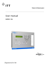
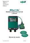
1
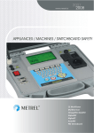
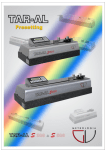
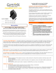
Manual MJK 704 Pump Controller As our products are developed continuously we reserve the right to make any M704US0402 1 change in the dimensions and the specifications. MJK North America, Inc. 37 Sherwood Terrace, #126 Lake Bluff, IL 60044 Tel: 847-482-8655 877 MJK LINK Fax: 847-482-8654 [email protected] www.mjk.com Manual UL Approvals UL-CUL listed, File # E 194021 UL 508/c22: 2 No. 142-M1987. CE Certificate of conformity This product complies with the requirements concerning electromagnetic compatibility (EMC) stipulated in Council directive no. 89/336/EEC of 3rd May 1989, altered at directive no. 92/31/EEC, on the approximation of the laws of the Member States relating to electromagnetic compatibility. We declare that the product complies to the values stipulated in EN 50081-1 and EN 50082-1. Ex approval of ultrasonic sensor Shuttle® Ultrasonic Sensor type 192L0570 is approved for mounting in explosive amospheres in zone 2 areas in accordance with EN 50021:1999. The approval are given by Demko under test no. 99Y.126020X. Therefore, Shuttle® is suited for use in potentially explosive atmospheres (Zone 2, Ex nA II T3), but not in Zone 1 or Zone 0 areas. The Shuttle® has not been approved for any other hazarduous rated zones. M704US0402 2 MJK North America, Inc. 37 Sherwood Terrace, #126 Lake Bluff, IL 60044 Tel: 847-482-8655 877 MJK LINK Fax: 847-482-8654 [email protected] www.mjk.com Manual Contents 1 1.1 1.2 General . . . . . . . . . . . . . . . . . . . . . . . . . . . . 5 Hydrostatic measuring system . . . . . . . . . . . 5 Ultrasonic measuring system . . . . . . . . . . . . 5 2 The front panel . . . . . . . . . . . . . . . . . . . . . . 5 3 3.1 3.2 3.3 3.4 3.5 3.6 Operation . . . . . . . . . . . . . . . . . . . . . . . . . . 6 Functional indications . . . . . . . . . . . . . . . . . . 6 F0 - Level measuring . . . . . . . . . . . . . . . . . . 6 F1 - Number of starts / Operational time . . . 6 F2 - Capacity / Quantity . . . . . . . . . . . . . . . . 6 F3 - Pumping station volume . . . . . . . . . . . . 6 F4 - Level Start/Stop and F5 - Level Set/Reset . . . . . . . . . . . . . . . . . . . 6 F6 - Forced start and F7 - Forced stop . . . . . . . . . . . . . . . . . . . . . 7 3.7 M704US0402 3 4 4.1 4.2 Programming of pump controller . . . . . . . 7 Language . . . . . . . . . . . . . . . . . . . . . . . . . . . 7 Key in access code . . . . . . . . . . . . . . . . . . . 7 5 5.1 5.2 5.3 5.4 5.4.1 5.4.2 5.4.3 5.4.4 5.4.5 5.4.6 5.4.7 5.4.8 5.4.9 Programming of main functions . . . . . . . . 8 Select unit measurement . . . . . . . . . . . . . . . 8 Select unit volume . . . . . . . . . . . . . . . . . . . . 8 Select unit flow . . . . . . . . . . . . . . . . . . . . . . . 8 Select special functions . . . . . . . . . . . . . . . . 8 Change the access code . . . . . . . . . . 8 Code only installation / all settings . . . . . 8 Measurement in level / elevation + level . . . 8 Depth pumping yes / no . . . . . . . . . . 8 Relay for depth pumping . . . . . . . . . . 8 Duty periods between depth pumping . . . 8 Depth pumping duration . . . . . . . . . . 8 Offset active / not active . . . . . . . . . . 8 Offset . . . . . . . . . . . . . . . . . . . . 8 6 6.1 6.2 6.3 6.4 6.5 6.6 Sensor menu - data for mounting . . . . . . . 9 Select sensor / span . . . . . . . . . . . . . . . . . . 9 Select comma . . . . . . . . . . . . . . . . . . . . . . . 9 Select span . . . . . . . . . . . . . . . . . . . . . . . . . 9 Key in elevation . . . . . . . . . . . . . . . . . . . . . . 9 Sensor level . . . . . . . . . . . . . . . . . . . . . . . . . 9 Max level . . . . . . . . . . . . . . . . . . . . . . . . . . . 9 MJK North America, Inc. 37 Sherwood Terrace, #126 Lake Bluff, IL 60044 Tel: 847-482-8655 877 MJK LINK Fax: 847-482-8654 [email protected] www.mjk.com Manual 7 7.1 7.2 7.3 7.4 7.5 7.6.1 7.6.2 7.6.3 7.7.1 7.7.2 7.8 Output relays programming . . . . . . . . . . . 10 Controlling of emptying / filling . . . . . . . . . . 10 Alternating normally / in pairs . . . . . . . . . . . 10 Relay programming . . . . . . . . . . . . . . . . . . 10 Relay operating / not operating . . . . . . . . . 10 Relay controlling / alarm . . . . . . . . . . . . . . . 10 Relay level alarm / system error . . . . . . 10 Relay NC / NO . . . . . . . . . . . . . . 10 Relay set>reset (high) / set<reset (low) . . 10 Relay alternating / directly controlled . . . 10 Level not in use / in use . . . . . . . . . . 10 Relay delay . . . . . . . . . . . . . . . . . . . . . . . . . 10 8 8.1 8.2 8.3 8.4 mA output programming . . . . . . . . . . . . . 11 mA output 0-20mA / 4-20mA . . . . . . . . . . . 11 mA output 4-20mA / 20-4 mA . . . . . . . . . . 11 mA output 4 mA = (elevation) . . . . . . . . . . . 11 mA output 20 mA = (elevation) . . . . . . . . . . 11 9 9.1 8.2 9.3 9.4 9.5 Pump flow programming . . . . . . . . . . . . . 11 Flow calculation yes / no . . . . . . . . . . . . . . 11 Level for volume: Stop . . . . . . . . . . . . . . . . 11 Level for volume: Start . . . . . . . . . . . . . . . . 11 Size of the volume . . . . . . . . . . . . . . . . . . . 11 Correction factor . . . . . . . . . . . . . . . . . . . . 12 10 Mounting . . . . . . . . . . . . . . . . . . . . . . . . . 13 10.1 Pressure Transmitter . . . . . . . . . . . . . . . . . . 13 10.2 Ultrasonic Sensor . . . . . . . . . . . . . . . . . . . . 13 10.3 Electrical connection . . . . . . . . . . . . . . . . . 14 10.3.1MJK 704 with pressure transmitter . . . . 14 10.3.2MJK 704 with ultrasonic transmitter . . . . 14 10.4 Connection box for transmitters . . . . . . . . . 15 11 Adjustments . . . . . . . . . . . . . . . . . . . . . . . 15 11.1 Level measurement . . . . . . . . . . . . . . . . . . 15 11.2 Zero point, span and response time . . . . . . 15 12 Maintenance . . . . . . . . . . . . . . . . . . . . . . . 15 13 Changing the software . . . . . . . . . . . . . . . 15 14 Dimensions . . . . . . . . . . . . . . . . . . . . . . . . 16 15 Order numbers . . . . . . . . . . . . . . . . . . . . . 17 16 Specifications . . . . . . . . . . . . . . . . . . . . . . 18 17 Settings form . . . . . . . . . . . . . . . . . . . . . . 19 18 Operational overview . . . . . . . . . . . . . . . . 20 19 Menu structure . . . . . . . . . . . . . . . . . . . . . 21 M704US0402 4 MJK North America, Inc. 37 Sherwood Terrace, #126 Lake Bluff, IL 60044 Tel: 847-482-8655 877 MJK LINK Fax: 847-482-8654 [email protected] www.mjk.com Manual 1 General the bottom of the solids to measure the hydrostatic pressure. The pressure transmitter transmits an electrical signal proportional to the pressure, resting on the pressure trans mitters membrane. The pressure transmitter is connected to the amplifier, where the sig nal is used for level indication, for limits for start-, stop signals and alarms, as well as for the level proportional 0-20/4-20 mA output signal. Pressure transmitters are supplied in 2 versions for absolute and gauge pressure. Thank you for choosing a MJK 704 Pump Controller. The MJK 704 Pump Controller is a microprocessor controlled pump controller, which is delivered with a hydrostatic measuring system or ultrasonic measuring system. The pump controller can control up to 4 pumps, valves etc. It is appropriate for plants, where the controller manages the data transfer to a central computer. The pump controller is operated with a combined menu and functional keyboard, making the installation and operation simple and clear. 1.2 Ultrasonic measuring system A MJK 704 Pump Controller delivered with a 30 kHz ultrasonic sensor with a resolution of 0.3 in. The ultrasonic sensor both sends and receives signals. In the amplifier the signals received from the sensor are converted to a signal proportional to the level. 1.1 Hydrostatic measuring system A MJK 704 Pump Controller delivered with a pressure transmitter, covering measuring ranges from 10 to 100 ft. The pressure transmitters are developed for measurement of waste water and liquids with suspended solids. All transmitters are designed as 2-wire 4-20 mA transmitters. Measurement is based on the following principle. A pressure transmitter is lowered to 2 The front panel LED indicators There are 4 LED‘s for indication of operation and alarms. The LED‘s is lit when an output is active - green when the relay output is used for control and red when used for alarm. The diode flashes during the delay period. With the ultrasonic sensor, the system has built in temperature compensation for accurate measurings at varying temperatures. Display 2 x 24 characters text display for indication of user menus and measuring values. When the keys have not been pressed for approx. 1 min, the display will change automatically to show the level. MENU By activating the MENU key, a shift is made to the next main menu to view the menu. 1 to 4 By pressing one of the keys from 1-4 (denominated as #) a reading of the built in datalogger is obtained for number and period of time, the output relays have been active. If flow calculation is applied, a second press will show the pump capacity and the volume pumped out. Third press will show the volume pumped out for the entire pumping station. ENTER With the ENTER key selections are confirmed. Also a shift from a main menu to a submenu is carried out with the ENTER key. START and STOP The level corresponding to the output relay is displayed by pressing one of the 8 start/stop keys. If the START key and one of the number keys are pressed simultaneously, the pumps are forced to start. If the STOP key and one of the number keys are pressed simultaneously, the pumps are forced to stop. M704US0402 5 Arrow keys The arrow keys are used for altering the current setting. In a submenu with the possibility to make a selection the top line will show the valid setting, the bottom line shows the alternative setting (in paranthesis). Use the arrow keys to select the desired settings. Input and output numbers are also changed by activating the arrow keys. By activating the ↑-key, the number of the display will increase. By activating the ↓-key the number will decrease the number. ESC (ESCape = undo): This key will take you back to the previous menu or undo a choice. By pressing the ESCkey 2-3 times you will always return to level indication. MJK North America, Inc. 37 Sherwood Terrace, #126 Lake Bluff, IL 60044 Tel: 847-482-8655 877 MJK LINK Fax: 847-482-8654 [email protected] www.mjk.com Manual 3 Operation If the MENU key is pressed while the functional indication F0 is in the display, access is given to reset the counter and time counter: The keys under the display give access to the functions used in the daily operation. The MENU key gives access to programming of the pump controller. The programming settings can be locked separately with an access code; ie. a code must be keyed in to get access to the programming menus. 3.1 Functional indications When the pump controller is connected to the mains the display will show: PROGRAM STARTUP 8340XX WAIT A MOMENT KEY IN NEW VALUES PRESS ENTER P# RESET TIME COUNTER? YES: ENTER NO: MENU NO: MENU P# CAPACITY QUANTITY 82 GPM 5508 CF The capacity of each single pump is shown at this point, as well as the pumped out volume. When pressing the MENU-key while functional indication F2, access is given to reset the capacity and water quantities (if code is not applied, see menu 3.3): If the sensor type is changed, or if an output relay is either put into service or out of service, the program will be reset and new values must be keyed in. 3.2 F0 - Level measuring When the programming is carried out, function F0, level measuring in the display is shown: MEASUREMENT Now the pump controller can be configured. The settings can always be altered later on. P# RESET COUNTER? YES: ENTER 3.4 F2 - Capacity / Quantity If key 1-4 is pressed while F1 is in the functional display, menu F2 will show: If the pump controller is activated for the first time, the display will show the following: 13.2 ft P# RESET CAPACITY YES: ENTER NO: MENU P# RESET QUANTITY YES: ENTER NO: MENU If the pump controller is set up for level output according to a given elevation, both the level and the level relative to the elevation is shown in the display: 3.5 F3 - Pumping station volume When pressing key 1-4 while functional indication F2 shows on the display, menu F3 will appear: MEASURING ELEVATION 4.5 ft 5.6 ft P# OPERATIONAL TIME M704US0402 27803 CF Displayed here is the pumped out volume for the entire pumping station, as the sum of the pumped out volumes from all the individual pump’s. If the MENU key is pressed, the volume can be reset: 3.3 F1 - Number of starts / Operational time By pressing one of the keys 1-4 the number of starts are displayed as well as the running hours / operation time for any of the relays 1-4 in use. If the relay is configured for operational relay the relay number is shown with a prepositive P for pumps. If the relays are configured as alarms an A will be shown. PUMPING STATION QUANTITY P2 RESET QUANTITY YES: ENTER NO: MENU STARTS 4 2.9 h 6 MJK North America, Inc. 37 Sherwood Terrace, #126 Lake Bluff, IL 60044 Tel: 847-482-8655 877 MJK LINK Fax: 847-482-8654 [email protected] www.mjk.com Manual 4 3.6 F4 - Level Start/Stop and F5 - Level Set/Reset By pressing START or STOP keys, the levels activating the relays can be read. If the relay is configured for controlling, the levels for starting and stopping the pump can be read. If the relay is configured as an alarm, the levels for setting and resetting can be read. If the pump controller is configured for filling (see menu 6.1) the start level will be lower than the stop level, and vice versa if the pump controller is configured for emptying. LEVEL 2 4.1 Language Choose between languages with the arrow keys. 4.2 Key in access code If access code has been chosen, key it into this menu before the following menus become accessible. Key in code with keys 1-4. Do not confirm with ENTER. START 1.80 STOP 0.20 If the relay is configured as a level alarm, there is an alternative choice of adjusting the set levels to be either higher (high alarm) or the contrary (low alarm) to the reset level in menu 6.6.3. LEVEL 1 Programming of pump controller When function F0 shows in the display press the MENU key for access to the programming menus (if code is not applied, see menu 3.3). Change between the main menus by repeatedly pressing the MENU key. Press ENTER to change to sub menus. Make choices and adjustments in the sub menus with the arrow keys and confirm with ENTER. When the code is keyed in, access is given to make alterations of all settings for 10 minutes after last key is pressed. SET 1.90 RESET 1.70 When adjusting a level, press one of the arrow keys; consequently the setting will flash. Set the wanted value with the arrow keys and confirm with ENTER. Double arrow alters the value quickly, single arrow alters the value slowly. The highest value acceptable is the equivalent of the max. level which has been programmed in menu 5.7. The lowest value acceptable is 1% of the measuring range of the sensor (reading in menu 5.1). The lowest range acceptable between start and stop is 1% of the max. level programmed into menu 5.7. NB: If level indication with elevation is applied, the values must be keyed in according to the elevation. 3.7 F6 - Forced start and F7 - Forced stop Forced controlling is carried out by pressing one of the keys 1-4 as well as the corresponding key for either start or stop. If the level is between the start and stop levels the pumps stay started or stopped when the keys are released. Above or below the interval between the start and stop levels, the pump is only started/stopped while the keys are pressed. The same applies if the level is not in use (menu 6.7.2). If a pump which is configured for alternating control is run forced, it is run as directly controlled during the forced running. As soon as the forced running is stopped the pump returns to alternating operation. M704US0402 7 MJK North America, Inc. 37 Sherwood Terrace, #126 Lake Bluff, IL 60044 Tel: 847-482-8655 877 MJK LINK Fax: 847-482-8654 [email protected] www.mjk.com Manual 5 Programming of main functions 5.4.4 Depth pumping yes / no This menu activates or deactivates the depth pumping function. Access to the configuring menus are obtained by pressing the MENU button. The function is used if the well should be emptied to a level below the normal stop level in a fixed time interval. 5.1 Select unit measurement Level indication and unit of elevation can be chosen as: 5.4.5 Relay for depth pumping Select which output relay that should start the depth pumping. ft, in, m, bar, kPa, cm, mm, l/s 5.2 Select unit volume Unit of volume can be chosen between 5.4.6 Duty periods between depth pumping This menu is used to enter the total number of starts (counted on all outputs) that should trigger a depth pumping. Gal, CF, m3, l 5.3 Select unit flow Unit of flow can be chosen between MGD, CFS, G/mi, m3/h, l/s 5.4.7 Depth pumping duration This menu is used to enter the interval (in seconds) the pump should continue to run after the normal stop level is reached. 5.4 Select special functions In this menu the submenu‘s for the special functions can be activated or deactivated. 5.4.8 Offset active / not active If OFFSET ACTIVE is selected, all start- and stop levels will be offset according to the selection in the next paragraph: 5.4.1 Change the access code This menu is used to change the access code. Press the MENU button if the code should remain unchanged. 5.4.9 Offset Select the offset value of all start / stop levels. 5.4.2 Code only installation / all settings The access code can block the access to installation settings only; ie. settings normally accessible via the MENU button, or it can block the access to all settings. If ALL SETTINGS is selected, changes are made via menu 2.0 where the access code is entered, whereafter access is given to all settings. 5.4.3 Measurement in level / elevation + level Select level indication as either absolute measurement or as relative measurement in relation to a given level. The level is the zero level chosen for the current location, ie. the pumping station level above sea level. If a pumping station is situated ie. 12 ft above sea level, a level measurement of 20 ft will be indicated as 32 ft. If elevation + level is selected, all start/stop values is programmed in relation to the level. M704US0402 8 MJK North America, Inc. 37 Sherwood Terrace, #126 Lake Bluff, IL 60044 Tel: 847-482-8655 877 MJK LINK Fax: 847-482-8654 [email protected] www.mjk.com Manual 6 Sensor menu - data for mounting 6.6 Max level The max level is set to restrict the setting of start and stop level. Use arrow keys for this setting. Double arrow changes the value before the comma, single arrow changes the value after the comma. Menus which are accessible, depend on the setup. The pump controller can be either an ultrasonic measuring system or a hydrostatic measuring system. The flow chart at the end of this manual, shows which of the following menus are accessible during system setup. 6.1 Select sensor / span In ultrasonic measuring systems, the sensor and the amplifier are calibrated together, and the measuring range of the sensor can be read. In the hydrostatic measuring system, the type of sensor applied can be coded into the system and the measuring scale of the sensor can be read. 6.2 Select comma When choosing selectable span in hydrostatic measuring systems, the comma is adjusted to set where the decimal point will be in the level readings. The choises are: 1.234, 12.35, 123.4 or 1234 6.3 Select span When choosing the selectable span with hydrostatic measuring systems, the span is set with the arrow keys. Double arrow changes the value before the comma, single arrow changes the value after the comma. 6.4 Key in elevation If level indication with elevation has been chosen, the elevation is keyed in at this point. For ultrasonic systems the elevation is keyed in as the 0-point of measuring. For hydrostatic measuring systems the sensor is placed in the zero point of the measurement, therefore the elevation for the sensor is keyed in. Use arrow keys for this setting. Double arrow changes the value before the comma, single arrow changes the value after the comma. 6.5 Sensor level For ultrasonic measuring systems the sensor elevation above the zero point is keyed in. Use the arrow keys for this setting. Double arrow changes the value before the comma, single arrow changes the value after the comma. M704US0402 9 MJK North America, Inc. 37 Sherwood Terrace, #126 Lake Bluff, IL 60044 Tel: 847-482-8655 877 MJK LINK Fax: 847-482-8654 [email protected] www.mjk.com Manual 7 Output relays programming 7.6.3 Relay set>reset (high) / set<reset (low) Set the level alarm to be registered as a high or low alarm. If the alarm needs to be a high alarm, choose set > reset. If the alarm needs to be a low alarm choose set < reset. In this menu the function for the four output relays are programmed. In menu 6.1 and 6.2 joint settings for the four outputs are programmed. In menu 6.3 to 6.8 the individual outputs are programmed. 7.7.1 Relay alternating / directly controlled The output relays can be set as directly controlled or alternating. At direct control, the start and stop values which have been keyed in for the individual relay activate the outputs, nothing else activates them. At alternating operation the alternating pumps will take it in turns to start up in a cycle, so that when a start level is activated the next relay in the cycle is activated. If several start levels are passed several pumps will consequently be started. 7.1 Controlling of emptying / filling The relays which are configured for control, are programmed to control either an emptying or a filling function. At the emptying function the pump-start levels are higher than the pump-stop levels. At the filling function the pump-start levels are lower than the pump-stop levels. 7.2 Alternating normally / in pairs At this point the outputs programmed to run as alternating (see menu 6.7.1), can be set up to run normally or in pairs. 7.7.2 Level not in use / in use To avoid all pumps running at the same time in alternating operation, levels can be left unused. At normal alternating, there is alternating between all the outputs which are set up to alternate. One level minimum, must be left “in use” for the pump controller to function correctly. If the pump controller is set up to alternate in pairs at least one of level 1 and 2 as well as either level 3 or 4 must be left “in use”. At alternating in pairs, output 1 and 2 are alternated as one of the pairs and between output 3 and 4 as the other pair. If alternating in pairs is chosen all four outputs are used as alternating, and it is therefore not possible to configure any of the relays as alarms or as directly controlled. 7.8 Relay delay To avoid short error conditions, or levels continuosly activating the relays, a delay time can be set. If the connected pumps are not started simultaneously for over load reasons, the delay time can be set differently for the relays. 7.3 Relay programming Choose with arrow keys or key 1-4 which output relay is to be programmed, confirm choice with ENTER. 7.4 Relay operating / not operating Choose whether to have the relay operating or not operating. In case of an error condition or level continuosly exceeding, the diode will flash. If the condition proceeds after the delay time has expired the relay will be activated and the diode will be permanently lit. 7.5 Relay controlling / alarm Set whether the relay is to be an alarm relay or a pump controlling relay. When the relays are activated, the light emitting diodes under the display will show, whether it is an alarm relay or a control relay: When an alarm relay is activated the diode will flash a red light; when a control relay is activated the diode will flash a green light. 7.6.1 Relay level alarm / system error If the relay is set for alarm relay, set the alarm to be a level (high/low) alarm or an alarm for system error. 7.6.2 Relay NC / NO Choose the relay function for the output, (Normally Open) or (Normally Closed). M704US0402 10 MJK North America, Inc. 37 Sherwood Terrace, #126 Lake Bluff, IL 60044 Tel: 847-482-8655 877 MJK LINK Fax: 847-482-8654 [email protected] www.mjk.com Manual 8 mA output programming 9 Set the voltage analog for the pump controller. Pump flow programming At flow calculation a known volume between two levels is programmed. The pump controller is then able to calculate the flow from the measured level differences. 8.1 mA output 0-20mA / 4-20mA Set the mA output as either a 4-20 mA signal or a 0-20 mA signal. In the flow calculation the fact, that inlets can occur simultaneously with pumping out is taken into consideration. 8.2 mA output 4-20mA / 20-4 mA Set the voltage output to be either 4-20 mA signal or 20-4 mA signal. To calculate flow the following conditions must be met: 1All start / stop levels must be outside the interval in which calculation takes place. If (0 or 4) - 20 mA is chosen, a high level will give a high mA-signal and a low level a low mA-signal. The flow calculation can only be carried out between the lowest set start level and the highest set stop level with a margin of sensor span/200. If 20 - (4 or 0) mA is chosen, a high level will give a low mA-signal and a low level a high mA-signal. 8.3 mA output 4 mA = (elevation) If 4-20 mA has been chosen in 7.2, key in which level the low mA value represents. If 20-4 mA has been chosen, the value represented by the high mA is set here. 2The connected pumps must regularly run on their own to obtain reliable flow measuring. 8.4 mA output 20 mA = (elevation) If 4-20 mA has been chosen in 7.2, key in here which level the high mA value represents. If 20-4 mA is chosen, key in the value represented by the low mA. If the above mentioned conditions are not present the following message will appear in the display, when entering menu 8.0 is attempted: PUMP FLOW NOT POSSIBLE SEE THE MANUAL This message will also appear if the pump settings are changed, so the conditions are no longer present. If flow calculation is needed again after this, the level must be set so the conditions are present again. If it is established that all stop / stop levels comply with the above conditions, access is given to menus 8.1 to 8.5. 9.1 Flow calculation yes / no Choose whether flow calculation is desired. 8.2 Level for volume: Stop Set the level where known volume stops. If the control is set for the filling function, the stop level is the highest level. If it is set for emptying, this is the lowest level. 9.3 Level for volume: Start Set the level for the known volume in this menu. If the control is set for filling, the start level is the lowest level, if it is set for emptying, this is the highest level. 9.4 Size of the volume At this point the known volume is keyed in, between start and stop level. The resolution of the volume will reflect the measurement accuracy of the pump controller. M704US0402 11 MJK North America, Inc. 37 Sherwood Terrace, #126 Lake Bluff, IL 60044 Tel: 847-482-8655 877 MJK LINK Fax: 847-482-8654 [email protected] www.mjk.com Manual 9.5 Correction factor It is possible to adjust a correction factor. As a starting point it should be reset at 1.00. If heights or other similar uncertain factors regularly occur, the flow can be adjusted by means of control measuring. M704US0402 12 MJK North America, Inc. 37 Sherwood Terrace, #126 Lake Bluff, IL 60044 Tel: 847-482-8655 877 MJK LINK Fax: 847-482-8654 [email protected] www.mjk.com Manual 10 Mounting 10.2 Ultrasonic Sensor When mounting the sensor, for example, at the top of a well or a container, ensure that no pipes or cables etc. are disturbing the path between the sensor and the liquid surface. The maximum distance between the sensor and the surface must not exceed the measuring range of the transmitter. Optimum operation is obtained by placing the sensor approx. 3 ft for 30 kHz sensor, and approx. 1.7 ft for the 100 kHz sensor, above the maximum liquid level. The sensor should be positioned perpendicular to the liquid surface (check with a spirit level!). When installing the sensor, ensure that the signal is able to pass any obstruction, taking in consideration that signal spreads relative to the sensor/surface distance as described in the table. If the signal travels along a hard surface such as the side of a well or tank, the table values can be applied directly. Otherwise you may refer to the following mounting examples. 10.1 Pressure Transmitter When measuring in a well, it is advantageous to mount the transmitter in a tube, fastening it at the top of the tube by means of the fittings supplied. This mounting facilitates subsequent cleaning and inspection. 0.7 ft 6 ft 1 ft 12 ft 1.4 ft 18 ft 1.7 ft 24 ft 2 ft 30 ft Pressure transmitter mounted in tube Table with the signal spread compared to the sensor/surface distance M704US0402 13 MJK North America, Inc. 37 Sherwood Terrace, #126 Lake Bluff, IL 60044 Tel: 847-482-8655 877 MJK LINK Fax: 847-482-8654 [email protected] www.mjk.com Manual If a sensor is mounted above an obstruction ex. a concrete deck, we recommend that it should be installed as shown below: Min. table value + 100 % Min. table value + 100 % Min. 25 in (@ 30 kHz) 45° Sensor mounted in tube for scum protection. If the upward edges on the obstruction are angled as shown below, the sensor can be mounted as the following: Sensor mounted near the top of a closed container. When measuring through a hole in for example a metal plate or grate, a pipe that ends near the lower edge of the sensor should be applied as shown here: Min. table value + 50 % Pipe dia. = min. table value + 25 % 30 - 45° 10.3 Electrical connection Electrical connection of the pump controller for hydrostatic and ultrasonic measuring systems respectively. Note: 1: Conduit hubs are to be connected to the conduit prior to to the connection to the enclosure 2: Terminal tightening torque = 0.5 Nm 10.3.1MJK 704 with pressure transmitter Relay output 3 Relay output 4 Current signal out (0 / 4 - 20 mA) Relay output 2 Relay output 3 Relay output 4 Current signal out (0 / 4 - 20 mA) Communications port (RS232) Relay output 2 Relay output 1 Pressure transmitter Relay output 1 Mains supply 10.3.2MJK 704 with ultrasonic transmitter Mains supply Nr. 1 = Nr. 2 = Nr. 3 = Nr. 4 = Nr. 5 = M704US0402 brown red orange yellow black 14 Communications port (RS232) Ultrasonic sensor MJK North America, Inc. 37 Sherwood Terrace, #126 Lake Bluff, IL 60044 Tel: 847-482-8655 877 MJK LINK Fax: 847-482-8654 [email protected] www.mjk.com Manual 11 Adjustments 10.4 Connection box for transmitters Connection box 202922 is used for outdoor connections of cables from the pressure transmitter. The box is made of ABS plastic, and the housing meets NEMA 6X. The box is ventilated in consideration of the tube for pressure equalizing. This allows the cable to be extended with ordinary installation cable from the box. 11.1 Level measurement The MJK 704 Pump Controller is factory preset for level measurement with pumps or valve control. 11.2 Zero point, span and response time The MJK 704 Pump Controller is factory preset for level measurement in water. The response time is set to minimum at delivery. When replacing the transmitter or when using the MJK 704 Pump Controller for differential level measurement or measurements in pressure or vacuum tanks, it may be necessary to reset both the zero point and the span. The resetting is carried out by simulating the zero point and the span. Depending on the use, it may also be necessary to reset the response time. If the pump controller is used in liquids with a specific gravity different from that of water (e.g. sludge), the span will need to be adjusted. Connection box 200519 is used to connect the ultrasonic sensor with cable. The connection boxes have a plug for connection of an indicator. When the indicator is applied the lid is replaced with a display. If the MJK 704 Pump Controller is used in water with foam or uncalm surfaces, it might be nescessary to adjust the gain. 12 Maintenance The pump controller and the ultrasonic sensor does not require any particular maintenance. When cleaning the pressure transmitter, care must be taken not to damage the membrane. 13 Changing the software If the EPROM with the pump control software is to be replaced, you must follow these instructions: 1.Turn off the pump controller 2.Turn off all pumps, to ensure that no accidents will occur when the pump controller is turned back on. This can be accomplished by disconnecting the pumps at the terminals on the pump controller. 3.Remove the top lid 4.Remove the EPROM (IC5) from the socket, be very careful not to ruin the IC. To terminal 1-2-3 on MJK 704 5.Insert the new EPROM (IC5), the notch must face upwards as shown on printboard, be very careful not to ruin the IC. 6.Mount the top lid once again. 7.Configure the new pump control program. 8.Connect the pumps again. Connection box 202922 for pressure transmitter together with a local indicator display type 531. M704US0402 15 MJK North America, Inc. 37 Sherwood Terrace, #126 Lake Bluff, IL 60044 Tel: 847-482-8655 877 MJK LINK Fax: 847-482-8654 [email protected] www.mjk.com Manual 14 Dimensions MJK 704 Ultrasonic sensor Pressure transmitter Cable bracket Standard sensor bracket Universal bracket Short sensor bracket M704US0402 16 MJK North America, Inc. 37 Sherwood Terrace, #126 Lake Bluff, IL 60044 Tel: 847-482-8655 877 MJK LINK Fax: 847-482-8654 [email protected] www.mjk.com Manual 15 Order numbers MJK 704 Pump Controller without pressure transmitter 209030: 209031: MJK 704 Pump Controller, 4 - 20 mA input MJK 704 Pump Controller, 4 - 20 mA input with galvanically separated 4-20 mA output MJK 704 Pump Controller with Pressure Transmitter 209035: 209036: 209040: 209041: MJK 704 Pump Controller, range 0 - 10 ft. MJK 704 Pump Controller, range 0 - 10 ft., with galvanically separated 4 - 20 mA output MJK 704 Pump Controller, range 0 - 30 ft. MJK 704 Pump Controller, range 0 - 30 ft., with galvanically separated 4 - 20 mA output MJK 704 Pump Controller with Ultrasonic Sensor 209060: 209061: MJK 704 Pump Controller, range 0 - 30 ft. MJK 704 Pump Controller, range 0 - 30 ft., with galvanically separated 4 - 20 mA output Accessories for Pump Controller 200105: 200115: Panel mounting kit Sun shield Accessories for Ultrasonic Sensor 200590: 200110: 200219: 200220: 200205: Connection box for cable for Ultrasonic sensor Cable for ultrasonic sensor (specify cable length) Sensor bracket, short Sensor bracket, standard Universal bracket Accessories for Pressure Transmitter 202922: 202923: 202920: 200112: M704US0402 Connection box for cable for pressure transmitter Connection box for cable for pressure transmitter with programming connector Non-standard cable lengths (+ cable per ft. in addition to standard 40 ft. cable) Cable for pressure transmitters (specify cable length) 17 MJK North America, Inc. 37 Sherwood Terrace, #126 Lake Bluff, IL 60044 Tel: 847-482-8655 877 MJK LINK Fax: 847-482-8654 [email protected] www.mjk.com Manual 16 Specifications Ultrasonic sensor Measuring range: Beam frequency: Spread: Temperature range: Dimensions: Materials: Cable: Approvals: Enclosure: 6 - 30 ft 30 kHz 3° - 5 … + 150 °F, built-in temperature compensation dia. 4.06 in x 3.07 mm PP (green) / POM (black) Shielded, oil resistant PVC insulation, length 40 ft. (Max. length 300 ft.) Ex (EEx nA II T3) and CE (EN 50081-1 / EN 500082-1) NEMA 6P, waterproof, withstands submersion (max. 3 ft.) Pressure transmitter Measuring ranges: Output: Accuracy: Temperature range: Dimensions: Materials: Cable: Approvals: 0 - 10 ft. relative pressure 0 - 30 ft. relative pressure 2-wire, 4-20 mA ≤1% +15 … + 150 °F Dia. 2,36 x 5,51 in PP (green) / POM (black), membrane from stainless steel (AISI 316 L) 2 x AWG 20, shielded, oil resistant PVC insulation. Length 40 ft. (Can be extenden) CE (EN 50081-1 / EN 500082-1) Kapsling: NEMA 6P, submersible down to 100 ft. Preslev® / Sonolev® Pump Controller: Measuring range: Voltage supply: Temperature range: Input signal: Accuracy: Outputs: Determined by sensor 110-120 (220 - 240 / 24V AC), power consumption 10 W (approx.) - 5 … + 150 °F From Ultrasonic Sensor, Pressure Transmitter or 4 - 20 mA input signal ≤ 1% Analog: 0 - 20 / 4 - 20 mA, max. 500 Ω loop resistance Digital: 4 x relays with voltage free switching contacts Max. load: 250 V, 4 A resistive load, max. 100 W inductive load. Dimensions: Height 7.28 ", width 9.45 ", depth 4.53 " Materials & enclosure:Polystyrol with transparent lid, NEMA 4X Approvals: UL-CUL listed, file # 194021 UL 508/c22: 2 No. 142-M1987 M704US0402 18 MJK North America, Inc. 37 Sherwood Terrace, #126 Lake Bluff, IL 60044 Tel: 847-482-8655 877 MJK LINK Fax: 847-482-8654 [email protected] www.mjk.com Manual 17 Settings form Pumping Station name: Pumping Station no.: Date: Serial no.: Sensor no.: ACCESS CODE yes MEASURING SYSTEM no CONTROLLER FOR ultrasonic hydrostatic level level and altitude code pump out pump in ALTERNATING sensor and span select unit select comma m bar 1 . 234 kPa 12 . 34 cm 123 . 4 mm normal in pairs at level alarm relay delay 1234 select span altitude sensor altitude max. level sensor level (704U) RELAY PROGRAMMING in use yes relay for no control at control alarm alternating direct at alternating at alarm control level in level not system level use in use failure alarm relay 1 set > reset set < reset sec. relay 2 sec. relay 3 sec. relay 4 sec. mA mA span 4 - 20 mA 0 - 20 mA OUTPUT mA orientation 0/4 - 20 mA 20 - 0/4 mA 0 / 4 mA = 20 mA = PUMPFLOW CALCULATION yes no level for volume – start level for volume – stop the volumes capacity correction factor START / STOP LEVELS start stop relay 1 relay 2 relay 3 relay 4 M704US0402 19 MJK North America, Inc. 37 Sherwood Terrace, #126 Lake Bluff, IL 60044 Tel: 847-482-8655 877 MJK LINK Fax: 847-482-8654 [email protected] www.mjk.com Manual 18 Operational overview M704US0402 20 MJK North America, Inc. 37 Sherwood Terrace, #126 Lake Bluff, IL 60044 Tel: 847-482-8655 877 MJK LINK Fax: 847-482-8654 [email protected] www.mjk.com Manual 19 Menu structure IF CODE 1.0 2.0 LANGUAGE ENGLISH FRANCAIS DEUTSCH ITALIANO NEDERLANDS DANSK NORSK SVENSKA 5.0 3.0 ENTER CODE KEY 1-2-3-4 XXXX SENSOR MENUES DEPENDENT ON THE MEASURING SYSTEM AND THE LEVEL INDICATION PROGRAMMING OF MAIN FUNCTIONS 3.1 ACCESS CODE 6.0 RELAY OUTPUT PROGRAMMING 6.1 CONTROL F. PU PU IN USE NOT IN USE IF CODE 6.2 3.2 ALTERNATING KEY IN NEW ACCESS CODE KEY IN 1-2-3-4 XXXX IF CODE 6.3 3.3 RELAY # PROGRAMMING CODE ONLY INSTALLATION ALL SETTINGS 6.4 4.0 RELAIS # MEAS. IN LEVEL ELEVATION+LEVEL IN US NOT IF IN US 6.5 4.1 UNIT MEASUREMENT RELAY # ft mm CON ALA 4.2 UNIT VOLUME Gal m3 4.3 UNIT FLOW ULTRASONIC MEASURING SYSTEM WITH LEVEL INDICATION 5.0.1 ULTRASONIC SENSOR DATA FOR MOUNTING 5.1.1 SENSOR/SPAN 0-10.00 m 5.6.1 SENSOR LEVEL HYDROSTATIC MEASURING SYSTEM WITH LEVEL INDICATION HYDROSTATIC MEASURING SYSTEM WITH ALTITUDE AND LEVEL INDICATION 5.0.2 5.0.3 5.0.4 HYDROSTATIC SENSOR DATA FOR MOUNTING ULTRASONIC SENSOR DATA FOR MOUNTING SENSOR/SPAN 0-10.00 m 5.1.3 0-30.0 ft XX,XX m MEASUR. HEIGHT 0-POINT LEVEL SELECT COMMA SELECT SPAN 5.7.2 MAX. LEVEL ELEVATION SELECT COMMA 3,00 MAX. LEVEL SELECT SPAN 3,00 5.5.4 XX,XX m RELAY # SET>RE SET<RE 6.8 SENSOR ELEVATION X,XX m LEVEL X,XX m MAX. LEVEL ELEVATION 21 RELAY # 6.6. 5.7.4 M704US0402 LEVEL SYST 6.6. X,XXX 5.4.4 5.7.3 X,XX m X,XX m RELAY # 5.3.4 X,XXX 5.4.3 SENSOR ELEVATION X,XX m LEVEL X,XX m 6.6. SELECT SENSOR/SPAN 0-XX,XX m IF LEVEL A 5.6.2 X,XX m 5.1.4 5.3.3 X,XX m X,XX m ALAR HYDROSTATIC SENSOR DATA FOR MOUNTING SELECT SENSOR/SPAN 0-XX,XX m 5.5.2 5.7.1 MAX. LEVEL ULTRASONIC MEASURING SYSTEM WITH ALTITUDE AND LEVEL INDICATION 5.1.2 0-30.0 ft l/s MGD X,XX m X,XX m MJK North America, Inc. 37 Sherwood Terrace, #126 Lake Bluff, IL 60044 Tel: 847-482-8655 877 MJK LINK Fax: 847-482-8654 [email protected] www.mjk.com RELAY # DELAY Manual 5.0 OR MENUES DENT ON THE NG SYSTEM AND EL INDICATION 6.0 7.0 RELAY OUTPUT PROGRAMMING mA OUTPUT PROGRAMMING 6.1 mA OUTPUT 6.2 8.1 4-20mA 0-20mA FLOWCALCULATION 7.2 NORMAL IN PAIRS mA OUTPUT 6.3 mA OUTPUT 4-20mA 20-4mA LEVEL FOR VOLUME 4mA 20mA IN USE NOT IN USE mA OUTPUT 20mA 4mA X,XX X,XX LEVEL FOR VOLUME STOP START 0,30 0,40 8.4 X,XX X,XX THE VOLUMES CAPACITY 2,00 m 3 8.5 CONTROL ALARM CORRECTION FACTOR 1,00 ATIC MEASURING WITH ALTITUDE VEL INDICATION 5.0.4 ALARM CONTROL 6.6.1 6.7.1 # sign valid for relay no. 1,2,3 & 4 6.5 RELAY # 0,30 0,40 8.3 7.4 IF IN USE STOP START TIC SENSOR MOUNTING 5.1.4 NSOR/SPAN 0-XX,XX m RELAY # 5.3.4 X,XXX RELAY # IF LEVEL ALARM ALTERNATING NO NC 6.7.2 6.6.3 3,00 RELAY # SET>RESET(HIGH) SET<RESET(LOW) 5.5.4 6.8 LEVATION X,XX m EVEL X,XX m RELAY # DELAY DIRECT CONTROLLED TEMPORARY OPERATION 6.7.3 STOP AFTER XXX MINUTES XX s LEVEL # 5.7.4 6.7.4 NOT IN USE IN USE 6.8 IF IN USE 6.8 X,XX m X,XX m RELAY # DELAY M704US0402 Distributed by: L ATION DIRECT CONTROLLED 6.6.2 5.4.4 AN RELAY # ALTERNATING RELAY # DELAY XX s XX s 22 Denmark MJK offices: OMMA LEVEL ALARM SYSTEM FAILURE Programming of Pump Controller 704 6.4 YES NO 8.2 7.3 RELAY # PROGRAMMING RELAIS # PUMPFLOW PROGRAMMING 7.1 CONTROL F. PUMPING OUT PUMPING IN ALTERNATING 8.0 www.mjk.dk [email protected] +45 45 56 06 56 MJK North America, Inc. North America 37 Sherwood Terrace, #126 Norway The Netherlands www.mjk.no [email protected] +47 69 20 60 70 www.mjk.com www.mjk.com Lake Bluff, [email protected] 60044 [email protected] 847-482-8655 +31 251Tel: 672171 +1 847 482 8655 Sweden Ireland www.mjk.se [email protected] +46 53 31 77 50 877 MJK LINK Australia Fax: 847-482-8654 www.mjk.com www.mjk.com [email protected] [email protected] [email protected] +353 87www.mjk.com 953 5625 +61 3 9755 1529