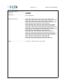
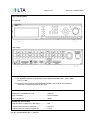
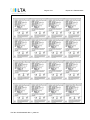
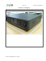
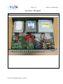
1
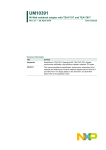
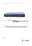
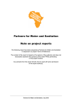
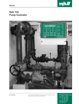
Page 1 of 41
TEST REPORT
IEC/EN 60065
Audio, Video and Similar Electronic Apparatus: Safety Requirements
Report Reference No. ...................... : LR500161004L
Tested by (name + signature) ............ : Ki-Kwan Chun
Approved by (name + signature) ........ : Kyung-Taek Lee
………………………………………
.......................................................
Date of issue ....................................... : 2010-04-16
Testing Laboratory .......................... : LTA Co., Ltd.
Address ............................................... : 243 Jubug-Ri, Yangji-Myeon, Cheoin-Gu, Yongin-Si, Gyeonggi-Do,
449-822, Korea.
Testing location/ address.................. : Same as above
Applicant’s Name ............................. : UNIMO Technology Co., Ltd.
Address ............................................... : 479-12 Bangbae-3Dong, Seocho-Gu, Seoul, 137-820 KOREA
Test Specification:
Standard.............................................. : EN 60065:2002 + A1:2006 + A11:2008
Test procedure .................................... : CE-LVD
Non-standard test method .................. : N/A
Test Report Form No. ...................... : IECEN 60065G
Test Report Form(s) Originator. ......... : ASTABEAB
Master TRF ......................................... : 2006-03
Copyright @ 2008 IEC System for Conformity Testing and Certification of Electrical Equipment
(IECEE), Geneva, Switzerland. All rights reserved.
This publication may be produced in whole or in part for non-commercial purposes as long as the IECEE is acknowledged
as copyright owner and source of the material. IECEE takes no responsibility for and will not assume liability for damages
resulting from the reader’s interpretation of the reproduced material due to its placement and context
TRF No. IEC/EN 60065G Rev. 2_2009-01
Page 2 of 41
Report No. LR500161004L
Test item description ...................... : Digital Hard Disk Recorder
Trade mark ......................................... :
UNIMO
Manufacturer .................................... : Same as applicant.
Model/Type reference ......................... : UDR-716E; UDR-716S; UDR-716V; UDR-716U; UDR-716CS;
UDR-716CE; UDR-716CV; UDR-716CU; UDR-716HS; UDR-716HE;
UDR-716HV; UDR-716HU; UDR-716S-ND; UDR-716E-ND;
UDR-716V-ND; UDR-716U-ND; UDR-716CS-ND; UDR-716CE-ND;
UDR-716CV-ND; UDR-716CU-ND; UDR-716HS-ND;
UDR-716HE-ND; UDR-716HV-ND; UDR-716HU-ND; UDR-708S;
UDR-708E; UDR-708V; UDR-708U; UDR-708CS; UDR-708CE;
UDR-708CV; UDR-708CU; UDR-708HS; UDR-708HE; UDR-708HV;
UDR-708HU; UDR-708S-ND; UDR-708E-ND; UDR-708V-ND;
UDR-708U-ND; UDR-708CS-ND; UDR-708CE-ND; UDR-708CV-ND;
UDR-708CU-ND; UDR-708HS-ND; UDR-708HE-ND;
UDR-708HV-ND; UDR-708HU-ND; UDR-704S; UDR-704E;
UDR-704V; UDR-704U; UDR-704CS; UDR-704CE; UDR-704CV;
UDR-704CU; UDR-704HS; UDR-704HE; UDR-704HV; UDR-704HU;
UDR-704S-ND; UDR-704E-ND; UDR-704V-ND; UDR-704U-ND;
UDR-704CS-ND; UDR-704CE-ND; UDR-704CV-ND;
UDR-704CU-ND; UDR-704HS-ND; UDR-704HE-ND;
UDR-704HV-ND; UDR-704HU-ND; UDR-316C; UDR-308C
Ratings ................................................ : 100–240 V
TRF No. IEC/EN 60065G Rev. 2_2009-01
; 50/60 Hz; Max. 70 W; Class I
Page 3 of 41
Report No. LR500161004L
Copy of marking plate:
-. Front design
-. Rear design
Summary of testing:
1. The appliance fulfills the requirements of the standard EN 60065:2002 + Amd 1:2006 +
Amd 11: 2008.
2. Compliance with European Special National Conditions, Annex ZB, and A-Deviations,
Annex ZC is recorded at the end of this report
Test item particulars:
Classification of installation and use..............................: Table top
Supply connection..........................................................: Cord connected
Class of equipment ........................................................: Class I
Possible test case verdicts:
- test case does not apply to the test object ................: N/A
- test item does meet the requirement ........................: Pass (P)
- test item does not meet the requirement ..................: Fail (F)
TRF No. IEC/EN 60065G Rev. 2_2009-01
Page 4 of 41
Report No. LR500161004L
Testing:
Date of receipt of test item .............................................: 2010-02-12
Date(s) of performance of test.......................................: 2010-02-12 until 2010-04-20
General remarks:
All tests were preformed and based on model UDR-716E
Model differences :
1. UDR-7XX[S/E/V/U]-[ND]
XX : Channel Number of 04, 08, 16
[S/E/V/U] : Alternate front design
[-ND] : No DVD-RW
This report shall not be reproduced, except in full, without the written approval of the Issuing testing laboratory.
"(see Enclosure #)" refers to additional information appended to the report.
"(see appended table)" refers to a table appended to the report.
Throughout this report, a comma is used as the decimal separator.
List of test equipment must be kept on file and available for review.
Remarks 1 – Factories
1. UNIMO Technology Co., Ltd.
479-12 Bangbae-3Dong, Seocho-Gu, Seoul, 137-820 KOREA
Remark 2 – The following contents that are included in this test report are:
1. Test Report: 41 pages
2. Attachment: 4 pages (Photograph)
General product information:
1. This apparatus is for indoor use only.
2. Protection class of apparatus: Class I
TRF No. IEC/EN 60065G Rev. 2_2009-01
Page 5 of 41
TRF No. IEC/EN 60065G Rev. 2_2009-01
Report No. LR500161004L
Page 6 of 41
TRF No. IEC/EN 60065G Rev. 2_2009-01
Report No. LR500161004L
Page 7 of 41
TRF No. IEC/EN 60065G Rev. 2_2009-01
Report No. LR500161004L
Page 8 of 41
TRF No. IEC/EN 60065G Rev. 2_2009-01
Report No. LR500161004L
Page 9 of 41
TRF No. IEC/EN 60065G Rev. 2_2009-01
Report No. LR500161004L
Page 10 of 41
Report No. LR500161004L
EN 60065
Clause
Requirement – Test
3
GENERAL REQUIREMENTS
─
Safety class of the apparatus ..................................: Class I apparatus
P
4
GENERAL CONDITIONS OF TESTS
─
4.1.4
Ventilation instructions require the use of the test
box
5
MARKING
Comprehensible and easily discernible
Permanent durability against water and petroleum
spirit
5.1
Result - Remark
No
On bottom
Maintained legibly and no
curling.
Class I apparatus
EN 60065
5.2
P
P
N/A
P
Frequency if safety dependant
P
50/60 Hz
For RATED POWER CONSUMPTION
measurements of TVs reference is made to EN
62087
No TVs
Earth terminal
(60417-2-IEC-5019)
marked near protective earth
terminal as protective earthing
conductor.
Hazardous live terminals
No hazardous live terminals
Supply output terminals (other than mains)
5.3
Use of triangle with exclamation mark
5.4
Instructions for use
5.4.1
P
Rated supply voltage and symbol ...........................: 100-240 V
Rated current or power consumption ......................: 70 W
5.1 i)
N/A
─
Identification, maker, model ....................................: (see the copy of marking plate)
Class II symbol if applicable
Verdict
N/A
P
N/A
P
In circuit diagram
In English
Mains powered equipment not exposed to dripping This instruction is expressed
or splashing. Warning concerning objects filled with on user’s manual.
”Do not use this appliance
liquid, etc.
near
water.”
Hazardous live terminals, instructions for wiring
P
P
P
P
N/A
Instructions for replacing lithium battery
No hazardous live terminals
The warning is explained on
service manual.
Instructions for modem if fitted
No modem
N/A
Class I earth connection warning
Class I apparatus
TRF No. IEC/EN 60065G Rev. 2_2009-01
P
P
Page 11 of 41
Report No. LR500161004L
EN 60065
Clause
Requirement – Test
Result - Remark
Instructions for multimedia system connection
No connectors for multimedia
system
Special stability warning for fixed installation
No fixed installation
Warning: battery exposure to heat
EN 60065
5.4.2
P
N/A
P
Warning: protective film on CRT face
5.4.1
Verdict
N/A
For a PORTABLE SOUND SYSTEM, a warning
that excessive sound pressure from earphones
and headphones can cause hearing loss
No PORTABLE SOUND
SYSTEM equipment
Disconnect device: plug/coupler or all-pole mains
switch location, accessibility and markings
Mains plug
Instructions for permanently connected equipment
No permanently connected
equipment
N/A
No ionizing radiation.
N/A
6
HAZARDOUS RADIATION
6.1
Ionizing radiation < 36 pA/kg (0,5 mR/h)
N/A
P
th
N/A
Laser radiation, emission limits to IEC 60825-1 .....: Class 1
P
Emission limits under fault conditions .....................: Class 1
P
7
HEATING UNDER NORMAL OPERATING CONDITIONS
─
7.1
Temperature rises not exceeding specified values,
no operation of fuse links
(see appended table)
P
7.1.1
Temperature rise of accessible parts
(see appended table)
P
7.1.2
Temperature rise of parts providing electrical
insulation
(see appended table)
P
7.1.3
Temperature rise of parts acting as a support or as (see appended table)
a mechanical barrier
P
7.1.4
Temperature rise of windings
(see appended table)
P
7.1.5
Parts not subject to a limit under 7.1.1 to 7.1.4
(see appended table)
P
7.2
Softening temperature of insulating material
supporting parts conductively connected to the
o
mains carrying a current > 0,2 A at least 150 C
(see appended table)
P
6.1
EN 60065
6.2
Directive 96/29/Euratomof 13 May 1996.
The dose-rate is determined by means of a
2
radiation monitor with an effective area of 10 cm ,
at any point 10 cm from the outer surface of the
apparatus < 1 µSv/h (0,1 mR/h)
TRF No. IEC/EN 60065G Rev. 2_2009-01
Page 12 of 41
Report No. LR500161004L
EN 60065
Clause
Requirement – Test
8
CONSTRUCTIONAL REQUIREMENTS WITH REGARD TO THE PROTECTION
AGAINST ELECTRIC SHOCK
─
8.1
Conductive parts covered by lacquer, paper,
untreated textile oxide films and beads etc.
considered to be bare
Considered
P
8.2
No shock hazard when changing voltage setting
device, fuse-links or handling drawers etc.
No devices accessible
8.3
Insulation of hazardous live parts not provided by
hygroscopic material
Not used
8.4
No risk of electric shock following the removal of a
cover which can be removed by hand
No cover removed by hand
8.5
Class I equipment
All clearances and creepage
distances between hazardous
live parts and earthed chassis
are separated more than 3,0
mm
8.6
Result - Remark
Verdict
N/A
P
N/A
P
Basic insulation between hazardous live parts and
earthed accessible parts
N/A
Resistors bridging basic insulation complying with
14.1 a)
P
Class II equipment and Class II constructions
within Class I equipment
Class I apparatus
Reinforced or double insulation between hazardous Class I apparatus. Reinforced
insulation provided between
live parts and accessible parts
hazardous live parts and
unearthed accessible parts on
power supply board.
Components bridging reinforced or double
insulation complying with 14.1 a) or 14.3
No such resistor
N/A
P
N/A
Basic and supplementary insulation each being
bridged by a capacitor complying with 14.1 a)
N/A
Reinforced or double insulation being bridged with
2 capacitors in series complying with 14.2.1 a)
N/A
Reinforced or double insulation being bridged with
a single capacitor complying with 14.2.1 b)
Sub-class Y1 : C21
P
Basic insulation bridged by components complying
with 14.3.4.3
N/A
8.7
This clause is void
N/A
8.8
Basic or supplementary insulation > 0,4 mm (mm) :
N/A
Reinforced insulation > 0,4 mm (mm) ....................: Transformer bobbin
: Min. 0,78 mm
TRF No. IEC/EN 60065G Rev. 2_2009-01
P
Page 13 of 41
Report No. LR500161004L
EN 60065
Clause
Requirement – Test
Result - Remark
Thin sheet insulation (excluding non-separable thin Insulation tape of three layers
between pri. winding and sec.
sheet insulation. See 8.22)
Winding on transformers(T1 &
T2) is used.
N/A
Basic or supplementary insulation, three layers any
two of which meet 10.3
N/A
Reinforced insulation, two layers each of which
meet 10.3
N/A
Adequate insulation between internal hazardous
live conductors and accessible parts
Adequate insulation between internal hazardous
live parts and conductors connected to accessible
parts
8.10
P
Basic or supplementary insulation, at least two
layers, each meeting 10.3
Reinforced insulation, three layers any two which
meet 10.3
8.9
Verdict
Double insulation between conductors connected
to the mains and accessible parts.
Insulation tape of three layers
between pri. winding and sec.
winding on transformer is
used.
All wires and cables
connected
to accessible parts are
secured
by cable ties from hazardous
live parts.
Insulation of wires connected
to hazardous live parts is PVC.
(> 0,4 mm Thick.)
All wires and cables are PVC.
(see clause 8.9)
P
Connector used
P
P
P
P
Double insulation between internal hazardous live
parts and conductors connected to accessible
parts.
8.11
Detaching of wires
No undue reduction of creepages or clearance
distances if wires become detached
N/A
Vibration test carried out .........................................: See clause 12.1.2
P
8.12
This clause is void
No mains socket-outlets
N/A
8.13
Adequate fastening of windows, lenses, lamp
covers etc. (pull test 20 N for 10 s)
No such pats.
N/A
8.14
Adequate fastening of covers (pull test 50 N for
10 s)
No such cover
N/A
8.15
No risk of damage to the insulation of internal
wiring due to hot parts or sharp edges
No risk of damage
8.16
Only special supply equipment can be used
No such apparatus designed
to
be supplied exclusively by a
supply apparatus.
TRF No. IEC/EN 60065G Rev. 2_2009-01
P
N/A
Page 14 of 41
Report No. LR500161004L
EN 60065
Clause
Requirement – Test
Result - Remark
8.17
Insulated winding wire without additional
interleaved insulation
N/A
8.18
Endurance test as required by 8.17
N/A
8.19
Disconnection from the mains
8.19.1
Disconnect device
Mains plug used
Verdict
P
P
All-pole switch or circuit breaker with >3mm contact
separation
N/A
8.19.2
Mains switch ON indication
N/A
8.20
Switch not fitted in the mains cord
8.21
Bridging components comply with clause 14
8.22
Non-separable thin sheet material
9
ELECTRIC SHOCK HAZARD UNDER NORMAL OPERATING CONDITIONS
─
9.1
Testing on the outside
P
9.1.1
For voltages >1000 V ac or >1500 V dc complies
with clause 13.3.1 for basic insulation
9.1.1.1
a) Open circuit voltages
P
b) Touch current measured from terminal devices
0,30 mA
using the network in annex D ..................................:
P
c) Discharge not exceeding 45 μC
< 45 µC
P
d) Energy of discharge not exceeding 350 mJ
15 kV not accessible
Both test probe B and probe
13
of IEC 61032
9.1.1.2
Test with test finger and test probe
9.1.2
No hazardous live shafts of knobs, handles or
levers
9.1.3
Ventilation holes and other holes tested by means
of 4 mm x 100 mm test pin
9.1.4
Terminal devices tested with 1 mm x 20 mm test
pin (10 N); test probe D of IEC 61032
Terminal devices tested with 1 mm x 100 mm
straight wire (1 N); test probe D of IEC 61032
P
N/A
No non-separable thin sheet
insulation
< 1000 V a.c., < 1500 V d.c.
N/A
N/A
P
P
The test pin did not reach
hazardous live parts
The test probe 16 did not
reach
hazardous parts
The test probe D did not reach
hazardous parts
9.1.5
Pre-set controls tested with 2.5 mm x 100 mm test
pin (10 N); test probe C of IEC 61032
9.1.6
No shock hazard due to stored charge on
4 V after 2 s
withdrawal of the mains plug; voltage (V) after 2 s .:
TRF No. IEC/EN 60065G Rev. 2_2009-01
N/A
No pre-set controls
P
P
P
N/A
P
Page 15 of 41
Report No. LR500161004L
EN 60065
Clause
Requirement – Test
Result - Remark
If C is not greater than 0,1 μF no test needed
9.1.7
Verdict
N/A
a) Enclosure sufficiently resistant to external force
P
Test probe 11 of IEC 61032 for 10 s (50 N)
P
b) Test hook of fig. 4 for 10 s (20 N)
P
c) 30 mm diameter test tool for 5 s (100 or 250 N) : 100 N applied
P
9.2
No hazard after removing a cover by hand
N/A
10
INSULATION REQUIREMENTS
10.1
Insulation resistance (MΩ) at least 2 MΩ min. after > 100 MΩ
surge test for basic and 4 MΩ min. for reinforced
insulation ..................................................................:
P
10.2
Humidity treatment 48 h or 120 h ............................: 48 h
P
10.3
Insulation resistance and dielectric strength
between mains terminals
P
(see appended table)
Insulation Resistance and dielectric strength across
BASIC or SUPPLEMENTARY insulation (Class 1)
N/A
Insulation resistance and dielectric strength across
REINFORCED insulation (Class II)
P
11
FAULT CONDITIONS
─
11.1
No shock hazard under fault condition
P
11.2
Heating under fault condition
P
No hazard from softening solder
P
Flames extinguish within 10 seconds
P
Soldered terminations not used as protective
mechanism
P
11.2.1
Measurement of temperature rises
(see appended table)
P
11.2.2
Temperature rise of accessible parts
(see appended table)
P
11.2.3
Temperature rise of parts, other than windings,
providing electrical insulation
(see appended table)
P
Temperature rise of printed circuit boards (PCB)
exceeding the limits of table 3 by max. 100 K for
max. 5 min
Not exceeded
N/A
a) Temperature rise of printed circuit boards (PCB) Not exceeded
to 20.1.3, exceeding the limits of table 3 by not
more than 100 K for an area not greater than 2 cm²
N/A
TRF No. IEC/EN 60065G Rev. 2_2009-01
Page 16 of 41
Report No. LR500161004L
EN 60065
Clause
Requirement – Test
Result - Remark
Verdict
b) Temperature rise of printed circuit boards (PCB)
to 20.1.3 up to 300 K for an area not greater than
2 cm² for a maximum of 5 min
N/A
Meets all the special conditions if conductors on
printed circuit boards are interrupted
N/A
Class I protective earthing maintained
N/A
11.2.4
Temperature rise of parts acting as a support or
mechanical barrier
Temperature rises are within
the limits
P
11.2.5
Temperature rise of windings
(see appended table)
P
11.2.6
Temperature rise of parts not subject to the limits
of 11.2.1 to 11.2.5
(see appended table)
P
12
MECHANICAL STRENGTH
12.1.1
Bump test where mass >7 kg
12.1.2
Vibration test
12.1.3
Impact hammer test
─
Mass: 6,56 kg
No damage & connection
loosening
N/A
P
P
Steel ball test
2 J; 0,4 m
P
12.1.4
Drop test for portable apparatus where mass < 7
kg
No damage
P
12.1.5
Thermoplastic enclosures strain relief test
12.2
Fixing of knobs, push buttons, keys and levers
12.3
Remote controls with hazardous live parts
12.4
Drawers (pull test 50 N, 10 s)
12.5
Antenna coaxial sockets providing isolation
N/A
12.6
Telescoping or rod antennas construction
N/A
12.6.1
Telescoping or rod antennas securement
N/A
13
CLEARANCE AND CREEPAGE DISTANCES
─
13.1
Clearances in accordance with 13.3
P
Creepage distances in accordance with 13.4
P
13.2
Determination of operating voltage
P
13.3
Clearances
P
13.3.1
General
P
13.3.2
Circuits conductively connected to the mains
comply with table 8 and, where applicable, table 9
TRF No. IEC/EN 60065G Rev. 2_2009-01
N/A
P
N/A
No drawers
(see appended table)
N/A
P
Page 17 of 41
Report No. LR500161004L
EN 60065
Clause
Requirement – Test
Result - Remark
Verdict
13.3.3
Circuits not conductively connected to the mains
comply with table 10
N/A
13.3.4
Measurement of transient voltages
N/A
13.4
Creepage distances
P
Creepage distances greater than table 11 minima
(see appended table)
P
13.5
Printed boards
N/A
13.5.1
Clearances and creepage distances between
conductors on printed circuit boards, one of which
may be conductively connected to the mains, as in
fig. 10
N/A
13.5.2
Type B coated printed circuit boards complying with
IEC 60664-3 (basic insulation only)
N/A
13.6
Conductive parts along uncemented joints
clearances and creepage distances comply with
13.3 and 13.4
Optocoupler
(see appended table)
P
Conductive parts along reliably cemented joints
comply with 8.8
Thickness between primary
and secondary of optocoupler:
≥ 0,4mm
P
Temperature cycle test and dielectric strength test
N/A
13.7
Enclosed, enveloped or hermetically sealed parts:
not conductively connected to the mains:
clearances and creepage distances as in table 12
N/A
13.8
Parts filled with insulating compound, meeting the
requirements of 8.8
N/A
14
COMPONENTS
14.1
Resistors
─
N/A
a) Resistors between hazardous live parts and
accessible metal parts
No such resistor used.
N/A
b) Resistors, other than between hazardous live
parts and accessible parts
No such resistor used.
N/A
Resistors separately approved ................................: No
14.2
Capacitors and RC units
N/A
P
Yes
(see appended table)
P
14.2.1
Y capacitors tested to IEC 60384-14, 2 edition ....: C21, C24, C25
(see appended table)
nd
P
14.2.2
X capacitors tested to IEC 60384-14, 2 edition ....: C1
(see appended table)
nd
P
Capacitors separately approved
TRF No. IEC/EN 60065G Rev. 2_2009-01
Page 18 of 41
Report No. LR500161004L
EN 60065
Clause
Requirement – Test
14.2.3
Capacitors operating at mains frequency but not
No
connected to the mains: tests for X2 ......................:
14.2.5
Capacitors with volume exceeding 1750 mm³,
< 1750 mm or metal can
where short-circuit current exceeds 0,2 A:
compliance with IEC60384-1, 4.38 category B or
better ........................................................................:
14.3
14.3.2
Verdict
N/A
3
N/A
Capacitors with volume exceeding 1750 mm³,
< 1750 mm or metal can
mounted closer to a potential ignition source than
table 5 permits: compliance with IEC 60 384-1,
4.38 category B or better .........................................:
3
N/A
Shielded by a barrier acc. to 20.1.4/ table 21 or
No barriers
metal ........................................................................:
N/A
Inductors and windings
Comply with IEC 61558-1, IEC 61558-2
(as relevant) and clause 20.1.4
14.3.1
Result - Remark
P
All parts of transformer and
line
filter are consist of
flammability
class V-1 or better
Transformers and inductors marked with
Coded number
manufacturer's name and type ...............................: (see appended table
Transformers and inductors separately approved ..: No
Transformer complies with
General
clause 14.3.3, 14.3.4.1 and
14.3.5.1
Insulation material complies with clause 20.1.4
Complies with clause 20.1.4
P
P
N/A
P
P
14.3.3
Constructional requirements
14.3.3.1
Clearances and creepage distances comply with
clause 13
Complied with the
requirements of clause 13
P
14.3.3.2
Transformers meet the constructional
requirements
Considered
P
14.3.4.1
Class II transformers have adequate separation
between hazardous live parts and accessible parts
(double or reinforced insulation)
Reinforced insulation between
the pri. and sec. windings :
3 layers of insulation tape
P
Coil formers and partition walls > 0,4 mm
(see appended table)
No such transformer used
(Windings of class II
construction)
Windings of class II
construction
Double or reinforced insulation
between hazardous live
windings and accessible
conductive parts
P
14.3.4.2
Class I transformers, with basic insulation and
protective screening only if all 7 conditions of
14.3.4.2 are met
14.3.4.3
Separating transformers with at least basic
insulation
14.3.5.1
Class II transformers have adequate insulation
between hazardous live parts and accessible parts
(double or reinforced insulation)
TRF No. IEC/EN 60065G Rev. 2_2009-01
P
N/A
N/A
P
Page 19 of 41
Report No. LR500161004L
EN 60065
Clause
14.3.5.2
14.4
Requirement – Test
Result - Remark
Coil formers and partition walls > 0,4 mm
(see appended table)
Windings of Class II
construction used
Class I transformers have adequate insulation
between hazardous live parts and accessible
conductive parts or those conductive parts or
protective screens connected to a protective earth
terminal
Verdict
P
N/A
Winding wires connected to protective earth have
adequate current-carrying capacity
N/A
High voltage components
N/A
High-voltage components and assemblies:
U > 4 kV (peak) separately approved
No high voltage components
used
N/A
Component meets category V-1 of IEC 60707
N/A
14.4.1
High voltage transformers and multipliers tested as
part of the submission
N/A
14.4.2
High voltage assemblies and other parts tested as
part of the submission
N/A
14.5
Protective devices
Protective devices used within their ratings
P
F1; 250V T3.15AL
External clearances and creepage distances meet Complied with the
requirement of clause 13 for the voltage across the requirements of basic
device when opened
insulations
14.5.1.1
14.5.1.2
No such thermal cut-outs
N/A
b) Thermal cut-outs tested as part of the
submission
Not tested
N/A
a) Thermal links separately approved
Not used
N/A
N/A
14.5.1.3
Thermal devices re-settable by soldering
No such thermal devices
14.5.2.1
Fuse-links in the mains circuit according to IEC
60127
(see appended table)
14.5.2.2
Correct marking of fuse-links adjacent to holder ....: F1; 250V T3.15AL
Not possible to connect fuses in parallel ................: Only 1 fuse provided. No fuse
holder so designed that
fuselinks
can be connected in
parallel
No replacement of fuse
Not possible to touch hazardous live parts when
replacing fuse-links without the use of a tool ..........: possible by hand
14.5.2.4
14.5.3
P
a) Thermal cut-outs separately approved
b) Thermal links tested as part of the submission
14.5.2.3
P
N/A
P
P
P
N/A
PTC-S thermistors comply with IEC 60730-1
Not used
N/A
PTC-S devices (15 W) category V-1 or better
Not used
N/A
TRF No. IEC/EN 60065G Rev. 2_2009-01
Page 20 of 41
Report No. LR500161004L
EN 60065
Clause
Requirement – Test
Result - Remark
Verdict
14.5.4
Circuit protectors have adequate breaking capacity
and their position is correctly marked
N/A
14.6
Switches
N/A
14.6.1 a)
Separate testing to IEC 61058 including:
N/A
10 000 operations
Normal pollution suitability
Resistance to heat and fire level 3
and
Make and break speed independent of speed of
actuation
V-0 compliance with annex G, G.1.1
14.6.1 b)
Tested in the apparatus:
N/A
Switch controlling > 0.2A with open contact voltage
> 35 V (peak)/24 V dc complying with 14.6.3,
14.6.4 and V-0 in annex G, G.1.1
N/A
Switch controlling > 0.2A with open contact voltage
< 35 V (peak)/24 V dc complying with 14.6.3 and V0 in annex G, G.1.1
N/A
Switch controlling < 0.2A with open contact voltage
> 35 V (peak)/24 V dc complying with 14.6.4 and
V-0 in annex G, G.1.1
N/A
14.6.2
Switch tested to 14.6.1 b) constructed to IEC
61058-1 subclause 13.1 and has making/breaking
action independent of speed of actuation
N/A
14.6.3
Switch tested to 14.6.1 b) compliant with IEC
61058-1 subclause 16.2.2 d) and m) not attaining
excessive temperatures in use
N/A
14.6.4
Switch tested to 14.6.1 b) has adequate dielectric
strength
N/A
14.6.5
Mains switch controlling mains socket outlets
additional tests to IEC 60058-1
14.7
N/A
Socket outlet current marking correct
N/A
Safety interlocks
N/A
Safety interlocks to 2.8 of IEC 60950
14.8
No socket outlet
No safety interlocks
Voltage setting devices and the like
Voltage setting device not likely to be changed
accidentally
14.9
Motors
14.9.1
Endurance test on motors
TRF No. IEC/EN 60065G Rev. 2_2009-01
N/A
N/A
No voltage setting devices
N/A
N/A
No motors
N/A
Page 21 of 41
Report No. LR500161004L
EN 60065
Clause
Requirement – Test
Result - Remark
Verdict
Motor start test
N/A
Dielectric strength test
N/A
14.9.2
Not adversely affected by oil or grease etc.
N/A
14.9.3
Protection against moving parts
N/A
14.9.4
Motors with phase-shifting capacitors, three-phase
motors and series motors meet clause. B.8, B.9
and B.10 of IEC 60950, Annex B
N/A
14.10
Batteries
14.10.1
Batteries mounted with no risk of accumulation of
flammable gases
14.10.2
No possibility of recharging non-rechargeable
batteries
No rechargeable batteries
P
14.10.3
Recharging currents and times within
manufacturers limits
P
Lithium batteries discharge and reverse currents
within the manufacturers limits
Max. abnormal charging
current: 10 mA
Normal reverse charging
current: 0 A
14.10.4
Battery mould stress relief
No batteries
N/A
14.10.5
Battery drop test
No batteries
N/A
14.11
Optocouplers
14.12
P
N/A
P
P
Optocouplers comply with Cl. 8
Insulation thickness: > 0,4 mm
P
Internal and external dimensions to 13.1. or
alternatively 13.6 (jointed insulation)
Int. > 4 mm
Ext. ≥ 6 mm
Thick. ≥ 0.4 mm
P
Surge suppression varistors
P
Comply with IEC 61051-2
Approved varistor
(see appended table)
Not connected between mains and accessible
parts except for earthed parts of permanently
connected apparatus
Complied
P
Complies with the current pulse, fire hazard and
thermal stress requirements of 14.12
Complied
P
15
TERMINALS
15.1.1
Mains plug, appliance inlet, interconnection
couplers and mains socket-outlet meet the
appropriate standard
Overloading of plugs or appliance inlets prevented
if the apparatus has mains socket outlets
TRF No. IEC/EN 60065G Rev. 2_2009-01
N/A
─
(see appended table)
P
N/A
Page 22 of 41
Report No. LR500161004L
EN 60065
Clause
Requirement – Test
Result - Remark
Overloading of internal wiring prevented if the
apparatus has mains socket outlets
15.1.2
Verdict
N/A
Connectors for antenna, earth, audio, video or data:
─
No risk of insertion in mains socket-outlets
Complied
P
No risk of insertion into audio or video: outlets
marked with the symbol of 5.2
No such risk of insertion
P
15.1.3
Output terminals of a.c. adaptors or similar devices Not compatible with household
not compatible with household mains socketmains socket-outlets
outlets
P
15.2
Provision for protective earthing
─
Accessible conductive parts of Class I equipment
reliably connected to earth terminal, within
equipment
Accessible metal enclosure is
reliably connected from
protective earth conductor of
appliance inlet
P
Protective earth conductors correctly coloured
Green / yellow
P
Equipment with non-detachable mains cord
provided with separate protective earth terminal
near mains input
Appliance inlet provided
Protective earth terminal resistant to corrosion
Combination of mild steel and
copper is under the line in
annex F
Earth resistance test: < 0,1 Ω at 32 A ....................: 0,012 Ω (at 32 A / 1 min.)
N/A
P
P
15.3
Terminals for external flexible cords and for
permanent connection to the mains supply
N/A
15.3.1
Adequate terminals for connection of permanent
wiring
N/A
15.3.2
Reliable connection of non-detachable cords:
Detachable power cord set
and appliance inlet provided
N/A
Not soldered to conductors of a printed circuit
board
N/A
Adequate clearances and creepage distances
between connections should a wire break away
N/A
Wire secured by additional means to the conductor
N/A
15.3.3
Screws and nuts clamping conductors have
adequate threads: ISO 261, ISO 262 or similar
N/A
15.3.4
Soldered conductors wrapped around terminal
prior to soldering or held in place by additional
means
N/A
Clamping of conductor and insulation if not
soldered or held by screws
N/A
TRF No. IEC/EN 60065G Rev. 2_2009-01
Page 23 of 41
Report No. LR500161004L
EN 60065
Clause
Requirement – Test
Result - Remark
15.3.5
Terminals allow connection of appropriate crosssectional area of conductors, for the rated current
of the equipment
15.3.6
Terminals to 15.3.3 have sizes required by table 16
P
15.3.7
Terminals clamp conductors between metal and
have adequate pressure
P
Terminals designed to avoid conductor slipping out Complied
when tightened or loosened
P
Terminals adequately fixed to avoid loosening
when the clamping is tightened or loosened and
stress on internal wiring is avoided
Complied
P
15.3.8
Terminals carrying a current more than 0,2 A:
contact pressure not transmitted by insulating
material except ceramic
No such terminals
N/A
15.3.9
Termination of non-detachable cords: wires
terminated near to each other
Detachable power cord set
used
N/A
N/A
Terminals located and shielded: test with 8 mm
strand
15.4
Verdict
N/A
Devices forming a part of the mains plug
N/A
The apparatus does not have
a device forming a part of the
mains plug
N/A
15.4.1
No undue strain on mains socket-outlets
15.4.2
Device complies with standard for dimensions of
mains plugs
N/A
15.4.3
Device has adequate mechanical strength (tests
a,b,c)
N/A
16
EXTERNAL FLEXIBLE CORDS
─
16.1
Mains cords sheathed type, complying with
PVC
IEC 60227 for PVC or IEC 60245 for synthetic
rubber cords ............................................................:
P
Non-detachable cords for Class I have
green/yellow core for protective earth
16.2
Mains cords conductors have adequate crossRated input current < 3 A
sectional area for rated current consumption of the
equipment
16.3
a) Flexible cords not complying with 16.1, used for
interconnections between separate units of
equipment used in combination and carrying
hazardous live voltages, have adequate dielectric
strength
TRF No. IEC/EN 60065G Rev. 2_2009-01
N/A
P
N/A
Page 24 of 41
Report No. LR500161004L
EN 60065
Clause
Requirement – Test
Result - Remark
Verdict
b) Flexible cords not complying with 16.1, withstand
bending and mechanical stress (3.2 of
IEC 60227-2)
N/A
16.4
Flexible cords used for connection between
equipment have adequate cross-sectional areas to
avoid temperature rise under normal and fault
conditions
P
16.5
Adequate strain relief on external flexible cords
16.7
N/A
Not possible to push cord back into equipment
N/A
Strain relief device unlikely to damage flexible cord
N/A
For mains cords of Class I equipment, hazardous
live conductors become taut before earth
conductor
16.6
Appliance inlet provided
Detachable power cord set
provided
Apertures for external flexible cord: no risk of
Appliance inlet provided
damage to the cord during assembly or movement
in use
Transportable musical instruments and amplifiers No musical instruments and
fitted with detachable cord set with appliance inlet
their associated amplifiers
to IEC 60320-1
Transportable musical instruments and amplifiers
fitted with detachable cord sets or with means of
stowage to protect the cord
N/A
N/A
N/A
N/A
17
ELECTRICAL CONNECTIONS AND MECHANICAL FIXINGS
─
17.1
Torque test to table 20:
P
- screws into metal: 5 times
Metal screw for fixing metal
enclosure used
3,9 mm of diameter: 1,2 Nm
P
- screws into non-metallic material: 10 times
N/A
17.2
Correct introduction into female threads in nonmetallic material
N/A
17.3
Cover fixing screws: captive
N/A
Non-captive fixing screws: no hazard when
replaced by a screw whose length is 10 times its
diameter
17.4
17.5
Captivity not necessary
No loosening of conductive parts carrying a current No such parts
> 0,2 A
No contact pressure
Contact pressure not transmitted through plastic
transmitted through insulating
other than ceramic for connections carrying a
current > 0,2 A
material
TRF No. IEC/EN 60065G Rev. 2_2009-01
N/A
N/A
P
Page 25 of 41
Report No. LR500161004L
EN 60065
Clause
Requirement – Test
Result - Remark
17.6
Stranded conductors of flexible supply cords
carrying a current > 0,2 A with screw terminals not
consolidated by solder
Appliance inlet provided
N/A
17.7
Cover fixing devices other than screws have
adequate strength and their positioning is
unambiguous
No such devices
N/A
17.8
Fixing devices for detachable legs or stands
provided
No such devices
N/A
17.9
Internal pluggable connections, affecting safety,
unlikely to become disconnected
Not disconnected
P
18
MECHANICAL STRENGTH OF PICTURE TUBES AND PROTECTION AGAINST
THE EFFECTS OF IMPLOSION
Picture tube separately approved to IEC 61965:
Verdict
─
No
N/A
Picture tube separately approved to 18.1 ................ No
N/A
Picture tubes > 16 cm intrinsically protected
N/A
Non-intrinsically protected tubes > 16 cm used with
protective screen
N/A
Protective film as part of implosion protection:
edges covered by enclosure
N/A
18.2
Intrinsically protected tubes: tests on 12 samples
N/A
18.2.1
Samples subject to ageing: 6
N/A
18.2.2
Samples subject to implosion test: 6
N/A
18.2.3
Samples subject to mechanical strength test (steel
ball): 6
N/A
18.3
Non-intrinsically protected tubes tested to 18.3
N/A
19
STABILITY AND MECHANICAL HAZARDS
─
Mass of the equipment exceeding 7 kg ..................: 7,69 kg
P
18.1
Apparatus intended to be fastened in place –
suitable instructions
o
No
N/A
19.1
Test on a plane, inclined at 10 to the horizontal
N/A
19.2
100 N force applied vertically downwards
N/A
19.3
100 N force, or 13% of weight, applied horizontally
to point of least stability.
N/A
TRF No. IEC/EN 60065G Rev. 2_2009-01
Page 26 of 41
Report No. LR500161004L
EN 60065
Clause
Requirement – Test
Result - Remark
19.4
Edges or corners not hazardous
There are no hazardous
edges
or corners when the appliance
is operating in normal position
19.5
Glass surfaces (exc.laminated) with an area
exceeding 0,1 m² or maximum dimension
> 450 mm, pass the test of 19.5.1
No glass surface
19.6
Wall or ceiling mountings adequate
20
RESISTANCE TO FIRE
─
20.1
Electrical components and mechanical parts
P
a) Exemption for components contained in an
enclosure of material V-0 to IEC 60695-11-10 with
openings not exceeding 1 mm in width
All components in this
apparatus are complied with
b).
All components are complied
Electrical components meet the requirements of
Clause 14 or 20.1.4
with this clause 20.1.1.
No wires working at voltages
Insulation of internal wiring working at voltages
> 4 kV
> 4 Kv or leaving an internal fire enclosure, or
located within the areas mentioned in Table 21, not (Insulation of all wires is PVC
contributing to the spread of fire
material)
PCB base material is of
Material of printed circuit boards on which the
flammability category V-0
available power exceeds 15 W at a voltage
between 50 V and 400 V (peak) a.c. or d.c. meets (see appended table)
V-1 or better to IEC60707, unless used in a fire
enclosure
PCB base material is of
Material of printed circuit boards on which the
available power exceeds 15 W at a voltage >400 V flammability category V-0
(peak) a.c. or d.c. meets V-0 to IEC 60707
(see appended table)
b) Exemption for small components as defined in
20.1
20.1.1
20.1.2
20.1.3
20.1.4
Verdict
P
N/A
N/A
N/A
P
P
N/A
P
P
Components and parts not covered by 20.1.1,
20.1.2 and 20.1.3 (other than fire enclosures)
mounted nearer to a potential ignition source than
the distances in Table 21 comply with the relevant
flammability category in Table 21
P
Components and parts as above but shielded from
a potential ignition source, with the barrier area in
accordance with Table 21 and fig. 13
N/A
Apparatus with voltages >4kV under normal
operating conditions and distances to the enclosure
exceed those specified Table 21, flammability
classification HB40 or better is required for the
enclosure.
N/A
TRF No. IEC/EN 60065G Rev. 2_2009-01
Page 27 of 41
Report No. LR500161004L
EN 60065
Clause
Requirement – Test
Result - Remark
Verdict
20.2
Fire enclosure
20.2.1
Potential ignition sources with open circuit voltage
> 4 kV (peak) a.c. or d.c. contained in a fire
enclosure to V-1
No voltages exceeding 4 kV
N/A
20.2.2
Internal fire enclosures with openings not
exceeding 1 mm in width and with openings for
wires completely filled
No internal fire enclosure
N/A
20.2.3
Requirements of 20.2.1 and 20.2.2 met by an
internal fire enclosure
Z1
RESISTANCE TO CANDLE FLAME IGNITION
N/A
N/A
─
EN 60065
A television set shall be so designed that the likelihood of ignition and the spread of
fire caused by a candle flame is reduced.
N/A
Exemption for the display screen of rear projection
TV’s
N/A
Wood and WOOD-BASED MATERIAL with a
thickness of at least 6 mm is considered to fulfil the
V-1 requirement when applying CLC/TS 62441
N/A
Television set meet the requirements of CLC/TS
62441
TRF No. IEC/EN 60065G Rev. 2_2009-01
No television set
N/A
Page 28 of 41
Report No. LR500161004L
EN 60065
Clause
Requirement – Test
Result - Remark
Verdict
A
APPENDIX A, ADDITIONAL REQUIREMENTS FOR APPARATUS WITH
PROTECTION AGAINST SPLASHING WATER
A.5.1
j) Marked with IPX4 (IEC 60529), 5.4.1 a) does not
apply
N/A
A.10.2.1
Enclosure provides protection against splashing
water
N/A
A.10.2.2
Humidity treatment carried out for 7 days
N/A
B
APPENDIX B, APPARATUS TO BE CONNECTED TO THE
TELECOMMUNICATION NETWORKS
─
─
Complies with IEC 62151 clause 1
N/A
Complies with IEC 62151 clause 2
N/A
Complies with IEC 62151 clause 3 but with 3.5.4
modified to 2.4.10 of this standard
N/A
Complies with IEC 62151 clause 4 but with 4.1.2,
4.1.3 and 4.2.1.2 modified in accordance with
annex B of this standard
N/A
Complies with IEC 62151 cause 5 but with 5.3.1
modified in accordance with annex B of this
standard
N/A
Complies with IEC 62151 clause 6
N/A
Complies with IEC 62151 clause 7
N/A
Complies with IEC 62151 annex A, B and C
N/A
L
APPENDIX L, ADDITIONAL REQUIREMENTS FOR ELECTRONIC FLASH
APPARATUS FOR PHOTOGRAPHIC PURPOSES.
L5.4
Marking and Instructions
N/A
L9.1.1
Terminals to connection to synchroniser not
HAZARDOUS LIVE
N/A
L7.1.5 &
Lithium batteries meet permissible temp rise in
Table 3 , unless comply with 6.3.2 of IEC 60086-4
N/A
Mains switch characteristics appropriate to its
function under normal conditions
N/A
L11.2.6
L14.6.6
─
N/A
TRF No. IEC/EN 60065G Rev. 2_2009-01
Page 29 of 41
Report No. LR500161004L
EN 60065
Clause
Requirement – Test
Result - Remark
Verdict
7.1
TABLE: temperature rise measurements
P
Power consumption in the OFF/Stand-by position
0 /1,8 W
of the functional switch (W) .....................................:
—
Operating conditions
- 500 mA loaded at IF INPUT terminal.
- Continuous operation.
Un (V)
In (A)
Pn (W)
Pout (W)
50 Hz
60 Hz
50 Hz
60 Hz
90
0,356
0,361
18,87
18,87
Max. output rated load
100
0,328
0,332
18,63
18,64
Max. output rated load
240
0,174
0,175
18,27
18,28
Max. output rated load
264
0,164
0,165
18,34
18,35
Max. output rated load
Loudspeaker impedance (Ω) ..................................: ─
—
Several loudspeaker systems
N/A
Marking of loudspeaker terminals
N/A
Monitored point:
dT (K)
Limit dT (K)
90 V / 60 Hz
264 V / 60 Hz
1. Transformer (T1) coil
39,8
40,3
75
2. Transformer (T1) core
35,0
36,4
─
3. Transformer (T2) coil
8,7
8,9
75
4. Transformer (T2) core
9,1
9,1
─
5. Line filter (LF1) coil
26,2
15,8
85
7. Heatsink of U1
15,0
12,8
─
8. PC1 body
23,6
28,3
─
9. PC2 body
13,9
13,6
─
10. PC3 body
8,4
8,5
─
11. Electrolytic capacitor (C3) top
12,9
12,7
─
12. Primary connector body, CN1
9,2
8,6
─
13. Internal enclosure
5,6
5,3
─
14. Internal wiring of power supply cord
8,9
8,5
60
15. Power PCB
12,2
11,2
─
16. Top enclosure
9,4
8,9
40
17. Front enclosure
3,1
2,4
60
TRF No. IEC/EN 60065G Rev. 2_2009-01
Page 30 of 41
Report No. LR500161004L
EN 60065
Clause
Requirement – Test
Result - Remark
Verdict
18. Bottom enclosure
4,0
4,1
40
19. Room ambient temperature
25,0
24,4
—
For switching mode transformer (T1) temperature rises were measured with thermocouples placed as close
as practicable to the winding. As the result. The permitted temperature rises were 10K less than given in
table 3.
Winding temperature rise measurements
N/A
o
—
o
—
Ambient temperature t1 ( C) ...................................: ─
Ambient temperature t2 ( C) ...................................: ─
Temperature rise dT of winding:
R1 (Ω)
R2 (Ω)
dT (K)
Limit dT (K)
Insulation
class
─
─
─
─
─
─
7.2
TABLE: softening temperature of thermoplastics
Temperature T of part
T - normal condio
tions ( C)
T - fault condio
tions ( C)
T softening
o
( C)
34,2
41,4
> 150
Primary connector, CN1
10.3
P
TABLE: insulation resistance measurements
Insulation resistance R between:
P
R (MΩ)
Required R (MΩ)
Between mains poles (primary fuse disconnected)
> 100
2
Between parts separated by basic or supplementary insulation
> 100
2
Between parts separated by double or reinforced insulation
> 100
4
Between transformer primary and secondary windings
> 100
4
Between transformer primary to core
> 100
2
10.3
TABLE: electric strength measurements
Test voltage applied between:
P
Test voltage (V)
Breakdown
Mains poles (primary fuse disconnected)
2120 Vd.c.
No
Between parts separated by basic or supplementary insulation
2120 Vd.c.
No
Between parts separated by double or reinforced insulation
4240 Vd.c.
No
Between transformer primary and secondary windings
4240 V d.c.
No
Between transformer primary to core
2120 V d.c.
No
TRF No. IEC/EN 60065G Rev. 2_2009-01
Page 31 of 41
Report No. LR500161004L
EN 60065
Clause
Requirement – Test
Result - Remark
11.2
TABLE: summary of fault condition tests
P
Voltage (V) 0,9 or 1,1 times rated voltage ..............: 100 V or 240 V
—
o
Ambient temperature ( C) .......................................: 23 – 26
fault condition, state component short- or
open circuited and components whose
temperature rises are measured
supply
voltage
—
result, state effect of fault condition and the duration of
the test
duration of
the test
Input
current(A)
1. TNR1
S/C
275
<1 s
-
2. BD1(AC to +)
S/C
264
1s
0
3. DB1 (AC to -)
S/C
275
<1 s
-
2. C3
S/C
264
1s
0
3. D10
S/C
264
10 min
0,33
4. D1
S/C
264
10 min
0,42
5. D2
S/C
264
10 min
0,015
6. U1 (pin 1-4)
S/C
264
1
0
7. U1 (pin 3-4)
S/C
264
10 min
0,015
8. U1 (pin 3-5)
S/C
264
53 min
0,36
TRF No. IEC/EN 60065G Rev. 2_2009-01
Verdict
result, state effect of fault
condition
Main fuse F1 was opened.
No overheated component.
No hazard.
F1 opened. BD1 damaged.
No hazard.
Main fuse F1 was opened.
No overheated component.
No hazard.
F1 opened. BD1 damaged.
No hazard.
Display unstable.
Function keys disabled.
No component damaged.
No hazard.
Normal operation.
No component damaged.
No hazard.
Immediately unit shutdown.
No component damaged.
No hazard.
F1 opened. U1 damaged.
No hazard.
Immediately unit shutdown.
No component damaged.
No hazard.
Display unstable.
Function keys disabled.
No component damaged.
Temperature stabilized at
T1 coil= 69,2 ºC; T2 coil=
37,5 ºC;
PCB(U1)= 53,8 ºC;
Room ambient= 28,7 ºC.
No hazard.
Page 32 of 41
Report No. LR500161004L
EN 60065
Clause
Requirement – Test
fault condition, state component short- or
open circuited and components whose
temperature rises are measured
Result - Remark
supply
voltage
result, state effect of fault condition and the duration of
the test
duration of
the test
Input
current(A)
9. D8
S/C
264
61 min
0,33
10. D7
S/C
264
10 min
0,33
11. U6
(1,2)
S/C
264
1s
0
12. U6
(2.8)
S/C
264
1s
0
13. U6
(2,7)
S/C
264
20 min
0,42
14. C8
S/C
264
10 min
0,015
15. C9
S/C
264
10 min
0,014
16. C11
S/C
264
10 min
0,014
17. C28
S/C
264
1 hr
0,373
17 min
TRF No. IEC/EN 60065G Rev. 2_2009-01
Verdict
result, state effect of fault
condition
Display unstable.
Function keys disabled.
No component damaged.
Temperature stabilized at
T1 coil= 69,7 ºC; T1 core=
61,2 ºC;
T2 coil= 35,0 ºC; PCB(U1)=
53,0 ºC;
Room ambient= 29,5 ºC.
No hazard.
Display unstable.
Function keys disabled.
No component damaged.
No hazard.
F1 opened. ZD2 and U6
damaged.
No hazard.
F1 opened. ZD2 and U6
damaged.
No hazard.
Normal operation.
No component damaged.
No hazard.
Immediately unit shutdown.
No component damaged.
No hazard.
Immediately unit shutdown.
No component damaged.
No hazard.
Immediately unit shutdown.
No component damaged.
No hazard.
Display unstable.
Function keys disabled.
No component damaged.
Temperature stabilized at
T1coil = 71,7 ºC; T1 core =
66,6 ºC;
T2 coil = 36,0 ºC; PCB(U1) =
56,1 ºC;
Room ambient= 24.4 ºC.
No hazard.
Page 33 of 41
Report No. LR500161004L
EN 60065
Clause
Requirement – Test
Result - Remark
fault condition, state component short- or
open circuited and components whose
temperature rises are measured
18. Fan
supply
voltage
Blocked
result, state effect of fault condition and the duration of
the test
duration of
the test
264
Input
current(A)
2 hr
0,42
8 min
19. Ventilation
S/C
264
3 hr
0,42
50 min
20. Output
(USB)
S/C
264
Verdict
2 hr
6 min
0,39
result, state effect of fault
condition
Normal operation.
No component damaged.
Temperature stabilized at
T1coil = 96,2 ºC; T2 coil =
56,4 ºC;
PCB(D4) = 80,5 ºC;
Room ambient= 24.4 ºC.
No hazard.
Normal operation.
No component damaged.
Temperature stabilized at
T1coil = 64.7 ºC; T2 coil =
33.3 ºC,
PCB(D4) = 54.7 ºC,
Room ambient= 24.4 ºC.
No hazard.
USB Shut-down.
Temperature stabilized at
T1coil = 67,5 ºC; T2 coil =
36,8 ºC;
PCB(D4) = 55,2 ºC;
Room ambient= 24.4 ºC.
No hazard.
S/C: Short-circuit, O/C: Open-circuit, NCD: No component damaged
Winding temperature rise measurements
N/A
o
—
o
—
Ambient temperature t1 ( C) ...................................: ─
Ambient temperature t2 ( C) ...................................: ─
TRF No. IEC/EN 60065G Rev. 2_2009-01
Page 34 of 41
Report No. LR500161004L
EN 60065
Clause
Requirement – Test
13
TABLES: clearances and creepage distances
Rated supply voltage:
250 V
Result - Remark
P
Pollution degree:
2
Material Group:
2 N force on internal parts applied:
Satisfactory
30 N force on outside of conductive enclosure applied:
Satisfactory
Location
Operating Voltage
V rms
Verdict
V peak
Clearance (mm)
Min
Actual
IIIa
Creepage (mm)
Min
Actual
Circuits conductively connected to the mains (use Tables 8, 9 and 11): see note below.
Across mains fuse F1 (B)
Across primary directly connected to the
mains (B)
Optocoupler(PC1) input to output (R)
240
360
2,0
6,6
2.3
6,6
240
360
2,0
4,1
2.3
4,1
175
348
4,0
6,3
4.8
6,3
Optocoupler(PC2) input to output (R)
173
348
4,0
6,3
4.8
6,3
Optocoupler(PC3) input to output (R)
173
348
4,0
6,3
4.8
6,3
Primary to Secondary (in Trans. T1) (R)
296
536
4,2
8,3
5.1
8,3
Primary to Secondary (in Trans. T2) (R)
260
408
4,0
7,9
4.2
7,9
Primary to accessible conductive parts
(on PCB) (B)
240
360
2.0
7,5
2.3
7,5
Notes:
1. Secondary circuits of Class II apparatus which have connector terminals that could be earthed (e.g. antenna signal input), are
subjected to the requirements for circuits conductively connected to the mains in Tables 8 and 9.
2. Floating secondary circuits of Class I apparatus which have connector terminals that could be earthed (e.g. antenna signal input),
are subjected to the requirements for circuits conductively connected to the mains in Tables 8 and 9 unless the floating secondary
circuit is separated from the primary circuits by an earthed metal screen (e.g. in the power transformer), or the floating secondary
circuit is connected to earth via a component such as a capacitor.
3. For insufficient clearances and creepage distances from secondary to secondary circuits and from secondary circuits to earth, see
Cl. 4.3.1, 4.3.2 and 11.2.
4. If the minimum creepage distance in Table 11 is less than the minimum required clearance in Tables 8, 9 or 10 as required, then
the value for clearance is used as the minimum creepage distance .
"Min" = minimum required.
"Actual = Actual dimensions measured.
14
TABLE: list of critical components and materials
Component
Manufacturer/
Type/model
Trademark
TRF No. IEC/EN 60065G Rev. 2_2009-01
P
Value / rating
Standard
Approval/
Reference
Page 35 of 41
Report No. LR500161004L
EN 60065
Clause
Requirement – Test
Component
Mains plug
Mains cord
Appliance
Coupler
Appliance inlet
HDD
Alt.
DVD Writer
Manufacturer/
Result - Remark
Type/model
Fan
Standard
Approval/
Trademark
Weihai Honglin
Co., Ltd.
HL-013
250 V; 10/16 A
Various
Various
10 A or 16 A;
250 V
DIN VDE 0620
EN 60884-1
VDE or
equivalent.*
Hwajin KDK
Co.,Ltd.
H05VV-F
H05VV-F 0,75
mm2 x 3C
DIN VDE 0620
EN 60227-5
EN 60557-1
EN 60227-2
VDE
Various
Various
3 x 0,75 mm2
Hwajin KDK
Co.,Ltd.
HL-026
250 V; 10 A
Various
Various
10 A or 16A;
250 V
DIN VDE 0281
VDE or
EN 60227-5
equivalent.*
EN 60557-1
EN 60227-2
DIN VDE 0625 VDE; NEMKO
EN 60799
EN 60320-1
DIN VDE 0627
VDE or
EN 60320-1
equivalent.*
DONG IL
Technology
DAC-12
250 V; 10 A
EN 60320-1
TUV-R; VDE
Samsung
Electronics Co.,
Ltd
Seagate
Technology Inc
HD2524HJ
12 Vdc / 0,7 A;
5 Vdc / 0,5 A
IEC 60950-1
EN 60950-1
TUV-R
ST3 or
3.5 Series
12 Vdc /
Max. 1,5 A;
5 Vdc /
Max. 1,5 A
IEC 60950-1
EN 60950-1
TUVNORD;
UL
Various
Various
12 Vdc; 5 Vdc
EN 60950 or
EN 60950-1
TUV-R or
equivalent. *
Toshiba
Samsung
Storage
TS-H653
12 Vdc / 1,5 A;
5 Vdc /
1,0 A or 1,5 A;
Class 1
IEC 60950-1
IEC 60825-1
NEMKO
12 Vdc / 5 Vdc
Class 1
IEC 60950-1
IEC 60825-1
NEMKO
+5 Vdc; +12 Vdc;
Class 1
+12 V; 0,09 A;
11,9 Cfm
EN 60950-1
EN 60825-1
NEMKO or
equivalent.*
EN 60950
TUV-PS
Technology
CD-RW /
DVD Drive
Value / rating
Verdict
Reference
SH-S203
Toshiba
Samsung
Storage
Technology
SH-M523
Various
Various
Power Logic
Technology
PL50B12L
TRF No. IEC/EN 60065G Rev. 2_2009-01
TS-H493
DIN VDE 0620 VDE; NEMKO
EN 60799
Page 36 of 41
Report No. LR500161004L
EN 60065
Clause
Requirement – Test
Component
Manufacturer/
Result - Remark
Type/model
Value / rating
Verdict
Standard
Trademark
Approval/
Reference
UL94
UL
Various
V-0 / HB; 60 °C;
min. 1,5mm
thick.
V-0 / HB or
better;
60 °C;
min. 1,5mm
thick.
UL94
UL
Hwan Duck
Electronics
1
V-0; 105 °C
UL94
UL
Come In Tech
3-V-0
V-0; 105 °C
UL94
UL
Various
Hitachi Maxell
Ltd
Various
CR2032 or
CR2032H
UL94
UL
UL 1462
UL
(MH12568)
Battery
protection IC
(U10)
Dallas
Semicond-uctor
Corp.
DS1339U
UL 60950-1
UL
(E99151)
Female
connector for
CN1
Han Lim
Electronics
CH1143-03
V-0; Min. 105 °C
3 V; Max.
abnormal
charging
current 10 mA;
Protected by
protection IC
(Dallas,
DS1339U)
TSSOP, 2,97–
5,5 V;
Max. 85 °C;
Te rating is
provided by mfg.
250 V; 7 A;
105 °C
DIN VDE 0627
TUV-R
Various
ORISEL Co.,
Ltd.
ORISEL Co.,
Ltd.
Various
250 V; 7 A
DIN VDE 0627
TUV-R
50F
250V; T3,15AL
EN 60127-1
EN 60127-2
VDE
N51
250V; T3,15AL
UL 248-1
UL 248-14
DENAN
UL; JET
(0902-31003-
Geo Young Ind.
Youchang
Electronics
GF-205B
UL512
UL
WBU 1942
250 V; 10 A
275 V; 0,22 uF;
X2
VDE; SEV;
FIMKO
Pilkor
Electronics
PCX2 335M or
PCX2 337
275 V; 0,22 uF;
X2
EN 132400,
IEC 60384-14
2nd
EN 132400,
IEC 60384-14
2nd
Material for front
panel, knobs
and door
PCB
Lithium Battery
(C641)
Fuse (F1)
Fuse holder
X-Capacitor (C1)
LG Chemical
AF312T /
HF-380
Various
TRF No. IEC/EN 60065G Rev. 2_2009-01
1006A)
VDE; FIMKO
Page 37 of 41
Report No. LR500161004L
EN 60065
Clause
Requirement – Test
Component
Manufacturer/
Result - Remark
Type/model
Value / rating
Varistor (VD1)
Trademark
Centra Science
Corp.
CNR-14D471K
Line filter (LF1)
Fine Industrial
Co., Ltd
LF-50UMC
Netron Tech
AA or AD
Daemyung
DE or DG
250 V; 1000 pF;
Y1 or Y2
Various
Various
Fine Industrial
Y-Capacitor / C24,
C25.
Electrolytic
capacitor (C3)
Main transformer
(T1)
Aux transformer
(T2)
Thermistor
(NT1)
Bridging
capacitor (C21)
Heat shrinkable
tube for fan lead
Optocoupler
(PC1, PC2,
PC3)
Standard
Verdict
Approval/
Reference
470 Vp
Peak Current:
4500 A
12 mH min.
(pin1-2/pin3-4);
Thermal class E
250 V; 1000 pF;
Y1 or Y2
CECC 42200
VDE
IEC 60065
Tested in
apparatus.
EN 132400,
IEC 60384-14
2nd
EN 132400,
IEC 60384-14
2nd
VDE; FIMKO
Min. 400 V;
105 °C;
Max. 150 uF.
IEC/EN 60065
Tested in
apparatus.
CMP50UM-C
Class A
IEC 60065
Tested in
apparatus.
Fine Industrial
CMP-50UMA
2 mH±10%
(pin1-pin2);
Insulation
Class E
IEC 60065
Tested in
apparatus.
Various
Various
5 ohm at 25 °C
IEC 60065
Tested in
apparatus.
Netron Tech
AD
250 V; 2200 pF;
Y1
VDE; FIMKO;
SEMKO
Dae Myung
Electronics
DG
250 V; 2200 pF;
Y1
EN 132400
IEC 60384-14
2nd
EN 132400
IEC 60384-14
2nd
Korea Expol
KEHS-225
Various
Various
Lite-On
LTV817B
600 V; 125 °C;
VW-1
Min. 300 V;
105 °C; VW-1
Viso = 5000V
int. / ext. / thick.
: 5,2 / 7,8 / 0,8
1
) an asterisk indicates a mark which assures the agreed level of surveillance
TRF No. IEC/EN 60065G Rev. 2_2009-01
VDE; FIMKO
VDE; FIMKO;
SEMKO
UL
UL
DIN VDE 0884 VDE; FIMKO
EN 60950-1
Page 38 of 41
Report No. LR500161004L
EN 60065
Clause
Requirement – Test
Remarks
N/A
TRF No. IEC/EN 60065G Rev. 2_2009-01
Result - Remark
Verdict
Page 39 of 41
Report No. LR500161004L
EN 60065
Clause
Requirement – Test
ZB
ANNEX ZB TO EN 60 065, SPECIAL NATIONAL CONDITIONS
─
2.6.1
DK: certain types of Class I apparatus, see 15.1.1, Class I apparatus
may be provided with a plug not establishing
earthing continuity when inserted in Danish socketoutlets
P
13.3.1
NO: In Norway, due to IT power distribution system
used, the a.c. MAINS supply voltage is considered
to be equal to the line-to-line voltage, and will
remain 230V in case of a single earth fault.
P
15.1.1
DK: mains cord for single-phase equipment having
a rated current not exceeding 10 A shall be
provided with a plug according to Heavy Current
Regulations Section 107-2-D1
P
DK: Class I equipment with socket-outlets with
earthing contact, or which are intended to be used
in locations where protection against indirect
contact is required shall be provided with a plug in
compliance with Standard Sheet DK 2-1a
N/A
DK: socket-outlets for providing power to Class II
equipment with a rated current of 2,5 A shall have
dimensions according to the drawing on page 179
of EN 60 065:2002 other dimensions shall be to
IEC 60 083 Standard Sheet C 1a for portable
socket-outlets
N/A
DK: mains socket-outlets with earthing contact
shall comply with Heavy Current Regulations
Section 107-2-D1, Standard Sheet DK 1-3a,
DK 1-5a or DK 1-7a
N/A
GB: equipment fitted with a flexible cable or cord
provided with a 13A BS 1363 plug as in Statutory
Instrument 1768:94
IE: equipment fitted with a flexible cable or cord
provided with a 13 A plug in accordance with
Statutory Instrument 525:97
Result - Remark
A power cord set provided
with
a 13A BS 1363 plug must be
supplied when apparatus is
sold in the market
A power cord set provided
with
a 13A plug must be supplied
when apparatus is sold in the
market
Verdict
P
N/A
NO: mains socket-outlets on Class II equipment meet CEE Publication 7 with the
following amendments:
N/A
- dimensions 2,5 A, 250 V socket-outlets shall
comply with Standard Sheet I page 180 of
EN 60 065:2002
N/A
- mechanical strength 2,5 A, 250 V socket-outlets
tested as specified in EN 60 065, 12.1.3
N/A
- protecting rim also tested
N/A
TRF No. IEC/EN 60065G Rev. 2_2009-01
Page 40 of 41
Report No. LR500161004L
EN 60065
Clause
Requirement – Test
Result - Remark
NO: method b) of 8.1 is not permitted. Double or
No TNV circuit provided
reinforced insulation is required between parts
connected to the mains and parts connected to the
public telecommunications network
Verdict
N/A
J.2
NO: In Norway, due to IT power distribution system
used, the a.c. MAINS supply voltage is considered
to be equal to the line-to-line voltage, and will
remain 230V in case of a single earth fault.
P
ZC
ANNEX ZC TO EN 60 065, A-DEVIATIONS
─
5
DE: additional markings required in German language:
N/A
- cathode ray tubes with an accelerating voltage
between 20 kV and 30 kV (marking on the tube)
N/A
5.1
- TV receivers whose picture tube has an
accelerating voltage between 20 kV and 30 kV
N/A
- TV receivers whose picture tube has an
accelerating voltage greater than 30 kV
N/A
- TV receivers whose picture tube has an
accelerating voltage less than 20 kV
N/A
IT: additional markings on the outside of the TV
receiver in Italian language
No TV receiver
N/A
IT: user instructions in Italian language including a
conformity declaration
Must be provided when sold in
the market
Must be provided when sold in
the market
N/A
IT: certification number on the back cover
14
No CRT
SE: Switches containing mercury such as
thermostats, relays and level controllers are not
allowed.
N/A
N/A
Amendment A1:2006 for
EN 60065:2002
This attachment considers the CENELEC modifications to IEC 60065/A1:2005 only
It can be used in conjunction with IEC TRF IECEN60065G
5.1 i)
Replace the note by:
NOTE: For RATED POWER CONSUMPTION
measurements of TVs reference is made to
EN62087. Measurements are done in the ON
(play) operating mode.
5.41
Add the following indent:
TRF No. IEC/EN 60065G Rev. 2_2009-01
Digital Video Recorder
N/A
Page 41 of 41
Report No. LR500161004L
EN 60065
Clause
Requirement – Test
Result - Remark
za) A warning that excessive sound pressure from
earphones and headphones can cause hearing
loss.
No earphones and
headphones
N/A
No ionizing radiation
N/A
6.1
Replace the subclause by:
6.1
Iionizing radiation
Verdict
Equipment that might produce ionizing radiation is
checked by measuring the amount of radiation.
N/A
The amount of radiation is determined by means of
a radiation monitor of the ionizing chamber type
with an effective area of 1000 mm2 or by
measuring equipment of other types giving
equivalent results.
N/A
Measurements are made with the equipment on
fest operating at the most unfavourable supply
voltage (See 4.2) and with operator controls and
service controls adjusted so as to give maximum
radiation whilst maintaining the equipment
operative for normal use.
N/A
Interna1 preset controls not intended to be
adjusted during the lifetime of the equipment are
not considered to be service controls.
N/A
At any point 100 mm from the surface of the
operator access area, the dose-rate shall not
exceed
N/A
1 pSv/h (0,1 mR/h)
(see Note). Account shall be taken of the
background level.
NOTE: These values appear in Directive
96/29/Euratom
TRF No. IEC/EN 60065G Rev. 2_2009-01
N/A
Page 1 of 4
Attachment – Photograph
▶Front view
TRF No. IEC/EN 60065G Rev. 2_2009-01
Report No. LR500161004L
Page 2 of 4
Attachment – Photograph
▶Rear view
TRF No. IEC/EN 60065G Rev. 2_2009-01
Report No. LR500161004L
Page 3 of 4
Attachment – Photograph
▶Inside view
TRF No. IEC/EN 60065G Rev. 2_2009-01
Report No. LR500161004L
Page 4 of 4
Attachment – Photograph
▶SMPS view
TRF No. IEC/EN 60065G Rev. 2_2009-01
Report No. LR500161004L