1
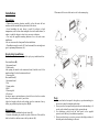
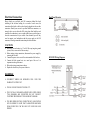
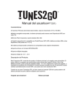
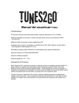
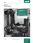
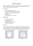
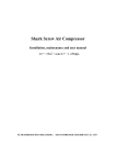
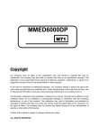
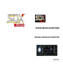
Car Stereo Receiver and Audio Player USER MANUAL AND INSTALLATION INSTRUCTIONS Model: RUSX123 Main Function: • • • • • • • • • • • • • AM/FM-MPX Electronic Tuning Radio Frequency Range: AM 530 – 1710 kHz; FM 87.5 – 107.9 MHz Radio Station Preset: 18 FM / 12 AM Detachable Front Panel Front USB Port and SD Card Slot Prepositive AUX Input Electronic Volume/Bass/Treble/Balance/Fade Control Preset EQ (POP, CLASS, ROCK, JAZZ) RCA Line Out (2-pairs) 200 Watts Total Max Output Power (50w x4) RMS Power: 25W x 4 Not a CD or DVD player For 12-volt DC Vehicle Only (12 V DC / 1 A) CAUTION This unit is designed to operate on 12-volts DC, negative ground electrical system only, do not attempt to install this unit in a vehicle having a positive ground system. Please do not install the unit to a +24V truck, bus or RV, otherwise the machine will be damaged. You should not touch the high-polished playback head with any metallic or magnetic tools. Please do not replace the power fuse without professional guidance. Improper use of fuses may cause damage or fire. To avoid electric shock caused by short circuit, or any unnecessary damage and fire, please prevent the product from a wet environment and water. Metal parts of this unit (especially on the back) become quite hot during operation, to be careful to avoid touching parts other than the handle immediately after removing the unit. Note: 1. When the machine is abnormal in operation, please tip the Reset key on the panel, the machine will resume to factory settings. 2. When the inside temperature of car is much higher or lower, please adjust the temperature in car first, then use the machine. 3. Avoid suffering strong attack, which will damage structural components of the machine. 4. Operate the unit in accordance with the instruction manual, damage caused by mal-operation is not covered under warranty. 5. Your unit has built-in filtering to eliminate most of the noise that might come through the power source. However, with some vehicles, particularly older models, some clicking or other unwanted noise might be present. Installation 3. Disconnect all the wires of the unit as well as the antenna plug. Precautions • Choose the mounting location carefully so that the unit will not interfere with the normal driving functions of the driver. • Avoid installing the unit where it would be subject to high temperatures, such as from direct sunlight or hot air from the heater, or where, it would be subject to dust, dirt or excessive vibration. • Use only the supplied mounting hardware for a safe and secure installation. • Be sure to remove the front panel before installation. • If installation angle exceeds 60° from horizontal, the unit might not give its optimum performance. (A) Step-by-Step Installation: Please refer to the illustration and detailed step-by-step installation below: Front installation (B) 1. Instrument board. 2. Metal mantle After putting the mantle in the instrument board, bend the steel of the mantle making it fixed to the instrument board. 3. Fastening bolt. Rear installation (C) 1. Instrument board 2. Nut 3. Spring washer 4. Bolt 5. Fastening bolt 6. Fixed steel In order to improve anti-interference, please fix the steel on the car under frame. You can bend the steel if you need to. Align the faceplate with the radio making sure the connectors line up before you push the faceplate into place. (D) (E) Dismantling: 1. Remove faceplate and then the plastic frame. (F) 2. Insert the dismantling key into the key hole of the device. Wait until the hook lock unlocks, and then remove the key and unit. (G) Note: Make sure that the front panel is the right way up when attaching it to the unit as it cannot be attached upside down. Do not press the front panel hard against the unit when attaching it. It can be easily attached by pressing it tightly against the unit. For safekeeping, always keep the front panel in the supplied protective case and keep it at moderate temperature. Do not press hard or give excessive pressure to the display window of the front panel when attaching it to the unit. Specification: FM Frequency Scope………………………………. 87.5MHz -107.9MHz Sensitivity…………………………………………………….. <26dB AM Frequency scope………………………………………….530-1710kHz Sensitivity……………………………………………………..…<43dB MP3 Sensitivity……………………………………………………… >35dB Frequency……………………………………….(100Hz -10KHz)+6dB Harmonic voltage distortion (1 KHz)………………………...….. <5% Channel Separation…………………………………………….... >35% Stereophonic reproduction channel balancing……………………...3dB Maximum effective power……………………………………....25Wx4 Output rating……………………………………………………...3Wx4 Power source…………….… 12v (10.8-15.1V) DC negative pole earth Speaker…………………………………………………………….4-8Ω Button and Key Function 1. POWER 2. CLK 3. 8. 4 9. 5/-10 4. 5. 1/ 6. 2/RPT 10. 6/+10 11. BAND 12. MODE 13. VOLUME 7. 3/RDM 14. RELEASE BUTTON 1. POWER: Switch on/off. 2. CLK: Clock button, press once then press again and hold it. Once the time starts to flash you can use the volume knob to adjust it. 3. : In radio mode to scan automatically(press). To find a station manually(press and hold). In mp3 mode it will be the “previous song” function. 4. : In radio mode to scan automatically(press). To find a station manually(press and hold). In mp3 mode it will be the “next song” function. 5. 1/ : In radio mode this will be the preset 1 button. In mp3 mode it will be the pause function. 6. 2/RPT: In radio mode this will be the preset 2 button. In mp3 mode it will be the repeat function. 7. 3/RDM: In radio mode this will be the preset 3 button. In mp3 mode it will be the random function. 8. 4: In radio mode this will be the preset 4 button. In mp3 mode this button does not have a function. 9. 5/-10: In radio mode this will be the preset 5 button. In mp3 mode it will go back 10 songs. 10. 6/+10: In radio mode this will be the preset 6 button. In mp3 mode it will go forwards 10 songs. 11. BAND: Press button to switch wave band, hold button for AMS function. 12. MODE: Switches the mode. 13. VOLUME CONTROL/SEL: (1) Turn this button to change the volume. (2) Each press will change the mode as follows: Volume>Bass>Treble>Balance>Fader (3) Hold down the button until LUD is displayed. Turn it to turn the LOUD function on or off. (4) Hold down the button until LUD shows then hold again until EQ show to change the equalizer settings. They go as follows: CLASS/POP/ROCK/JAZZ/EQ OFF 14. RELEASE BUTTON: Releases detachable panel. Electrical Connection Back Panel Drawing Many vehicles are pre-fitted with ISO connectors behind the dash, including all the electrical cabling for a car radio. In such cases, the connections fitted to the vehicle can be directly plugged into the car radio connectors. Should your car not be pre-fitted with these connectors, we strongly advise you to obtain the ISO wiring loom fitted with the male connector for connection to your car radio either from a specialist shop or from the concessionaire for your vehicle. Once obtained, you will only need to connect your loudspeakers and the power supply to the ISO connector, following connection instructions provided with same. CAUTION: Make sure your car battery is a 12 volt (6 filler caps) negative ground system (if not, a converter will be necessary). Before starting wiring connections, disconnect the power supply by removing the fuse box. Connect the power wire to one of the extra terminals of the fuse box. Connect the black ground wire to a metal part of the car. It is important to make good contact. Make other wiring connections as shown Replace the fuse in the yellow power lead wire. WARNING: INCORRECT WIRING OR OPERATION WILL VOID THE WARRANTY OF THIS UNIT. THE ISO CONNECTOR MUST NOT BE CUT. THE UNIT HAS 2 SEPARATE AMPLIFICATION STEPS. WHEN TWO SPEAKERS ARE CONNECTED DO NOT CONNECT TOGETHER THE WIRES BUT CHOOSE FRONT OR REAR. THE RED WIRE MUST BE CONNECTED BY CAR IGNITION KEY IN ORDER TO AVOID THAT CAR BATTERY BECOMES WEAK WHEN THE CAR WILL BE NOT USED FOR LONG PERIOD. RUSX123 Wiring Diagram TROUBLESHOOTING Before going through the check list, check wiring connection, if any of the problems persist after check list had been made, consult your nearest service dealer. Symptom Failure of being powered on No sound. Failure of Radio The radio station automatic selection does not work. Failure of reading USB or SD/MSD Noises and sound distortion Stop working SONDPEX CAR STEREOS Cause The car ignition switch is not ON The fuse is blown Volume is in minimum. Wiring is not properly connected. Antenna is not pulled out or connection is wrong. Weak signal The signals are too weak. Poor contact Speaker cables are pressed by screws Speaker cables are short-circuited CPU can not work normally Files are damaged Solution If the power supply is properly connected to the car accessory terminal switch the ignition key to “ACC” Replace the fuse Adjust volume to a desired level Check the wiring connection Properly connect the antenna and pull it out as long as possible Rotate the antenna to proper direction Select a station manually 1. Change the fuse Please make sure the amperage matches will all other fuses before changing them. If the fuse is burnt check the power supply first and then change the fuse. If the fuse is burnt again there may be internal problems, please contact the dealer. 2. Connector cleaning If the connector of the unit and the panel is dirty the unit may not work normally. In order to prevent this please remove the front panel and clean the connectors with spirituous cotton as shown on the picture below. CAUTION: For safety please switch off the engine and take the key out of the ignition before you clean the connector. Do not use your fingers or any metal to touch the connectors. Pull out the memory card and reinsert it Check the speaker cables Properly connect wires. Turn off the power and power it on again. Skip this file and please select next file Note: This manual instruction is for reference. Design and specifications are subject to be changed without notice. CAR AUDIO SYSTEMS