1
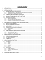
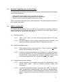
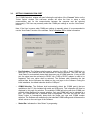
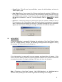
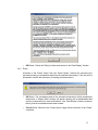
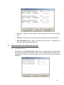
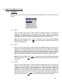
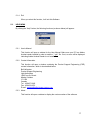
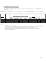
TABLE OF CONTENTS
1.
INTRODUCTION ........................................................................................................................................3
2.
GETTING STARTED ..................................................................................................................................3
2.1.
MINIMUM HARDWARE REQUIREMENT ..........................................................................................3
2.1.1.
WINDOWS 2000, NT, AND MILLENNIUM OPERATING SYSTEMS .........................................3
2.1.2.
WINDOWS XP OPERATING SYSTEM ......................................................................................3
2.2.
COMPUTER AND INSTRUMENT CONNECTION .............................................................................3
2.3.
MICROSOFT WINDOWS AND LAPTOP SETTINGS ........................................................................4
2.4.
GENERAL GUIDELINES....................................................................................................................4
2.4.1.
DROP-DOWN MENUS ...............................................................................................................4
2.4.2.
BUTTONS AND EDITABLE FIELDS...........................................................................................4
2.4.3.
RUNNING THE MAINTENANCE SOFTWARE ...........................................................................4
3.
USER INTERFACE OVERVIEW (SELECT OPTION MENU PAGE) .........................................................5
3.1.
SELECT OPTION WINDOW ..............................................................................................................5
3.2.
SETTING COMMUNICATION PORT .................................................................................................7
3.3.
AUTO DETECT...................................................................................................................................8
3.4.
DOWNLOAD AND ERASE EXCEEDANCE.......................................................................................9
3.4.1.
DOWNLOAD ...............................................................................................................................9
3.4.2.
ERASE ......................................................................................................................................11
3.5.
VIEW AND MODIFY INITIALIZED DATE AND TIME ......................................................................12
3.5.1.
VIEW DATE AND TIME ............................................................................................................12
3.5.2.
CHANGE DATE AND TIME ......................................................................................................13
4.
ERROR MESSAGE & TROUBLESHOOTING .........................................................................................14
4.1.
“ERROR DURING DOWNLOAD” ....................................................................................................14
4.2.
“NO VALID ADDRESS”...................................................................................................................15
4.3.
“TIMED OUT”...................................................................................................................................15
5.
USE OF FILE MENU FUNCTIONS ..........................................................................................................16
5.1.
FILE MENU.......................................................................................................................................16
5.1.1.
OPEN ........................................................................................................................................16
5.1.2.
PRINT .......................................................................................................................................16
5.1.3.
EXPORT ...................................................................................................................................16
5.1.4.
EXIT ..........................................................................................................................................17
5.2.
HELP MENU .....................................................................................................................................17
5.2.1.
USER’S MANUAL .....................................................................................................................17
5.2.2.
CONTACT INFORMATION.......................................................................................................17
5.2.3.
ABOUT......................................................................................................................................17
6.
SOFTWARE COMPATABILITY TABLE ..................................................................................................18
2
1. INTRODUCTION
This document is a user’s guide for the Model 407 “Propulsion Instrument Maintenance Software” (P/N
407-770-002-101). This tool enables the user to communicate on the RS485 bus with the model 407
propulsion instruments (specifically the MGT, NG and TRQ indicators) for the uploading and
downloading of maintenance information.
This program is useable in a Windows 2000, NT, Millennium, or XP environments in lieu of EPMPLUS
software that is useable in DOS, Window 95, and Windows 98 environments.
2. GETTING STARTED
2.1.
MINIMUM HARDWARE REQUIREMENT
The following are minimum recommended computer configurations to use this software.
2.1.1. Windows 2000, NT, and Millennium Operating Systems
o
o
o
o
IBM-Compatible machine (identified as laptop PC herein) with an Intel Pentium III @500Mhz
processor (or equivalent), or higher running.
2.5 Mbytes of free disk space.
One Serial or USB communication Port (used to connect to the Propulsion Instruments).
3 1/2-inch 1.44 MB floppy drive.
2.1.2. Windows XP Operating System
o
o
o
o
IBM-Compatible machine (identified as laptop PC herein) with an Intel Celeron @1.2Ghz
processor (or equivalent), or higher running.
2.5 Mbytes of free disk space.
One Serial or USB communication Port (used to connect to the Propulsion Instruments).
3 1/2-inch 1.44 MB floppy drive.
Note: If the USB Port is being used, it must be used with a USB to DB-9M Serial Connector
Adapter. This Adapter is also sold as USB PDA Adapter.
2.2.
COMPUTER AND INSTRUMENT CONNECTION
The laptop computer must be connected to the aircraft and Instruments (with aircraft DC
electrical power on) using the interface cable (P/N 407-275-001-103), an RS232/485 converter
(P/N 485LP9R or 485SD9R), and using the computer’s serial or USB communication port in
order to “Connect” or use any of the instrument functions.
Important Note: Ensure the RS232 side of the RS232/485 converter is plugged into the
computer’s serial or USB COMM port.
3
2.3.
MICROSOFT WINDOWS AND LAPTOP SETTINGS
The following Microsoft Windows and laptop PC settings are recommended for proper operation
of this Software Application.
o
o
o
Laptop screen savers should be set to more than five minutes.
Any laptop PC power or battery saving features should be disabled.
Disable or close non-essential programs that may be running.
Refer to the Microsoft Windows User’s Guide and laptop PC user documentation for details on
how to perform these tasks.
2.4.
GENERAL GUIDELINES
The various screens (windows) that are shown for this software are designed to keep the
standard philosophy of all programs developed in the Windows environment constant, and to
ensure a maximum of security in the user’s actions.
2.4.1. Drop-Down Menus
2.4.1.1.
2.4.1.2.
“Open”, “Print”, “Export”, and “Exit” options are grouped under the “File” dropdown menu.
The User’s Manual, Product Support Engineering contact information, and
“About” the software are grouped under the “Help” drop-down menu.
2.4.2. Buttons and Editable Fields
2.4.2.1.
Each window performing “critical” actions (e.g. “Erase”) contains a “CANCEL”
button to allow canceling of the request.
2.4.2.2.
All options are accessible through the use of shortcuts (i.e. without the need of
a mouse) by pressing the “ALT” key combined with the underlined letter of the
command button. As an example: the instrument “Download” function would
be accessed by pressing the “ALT” key and then the letter “D” together.
2.4.3. Running the maintenance software
2.4.3.1.
Start by powering up the computer using either the internal battery or the
external power supply.
Start the Windows operating system (OS)
environment.
2.4.3.2.
To start the maintenance software, double click the “M407” icon from the
“M407” program group or double click the “M407” from your Windows desktop.
The “Model 407 Propulsion Instrument Maintenance Software” start-up screen
appears, displaying the company logo, software part number and copyright
notice.
4
o
OK Button: This will proceed with the application to display the “Select Option” Menu
screen.
o
EXIT Button: To quit the Software and return to the Windows OS.
3. USER INTERFACE OVERVIEW (SELECT OPTION MENU PAGE)
The User interface to perform maintenance functions on the model 407 propulsion instrument suite is
separated into four groups of functions: Download Exceedance data, Upload Initialized date & time,
General, and Setting the appropriate COMM Port. The user interface is described below:
Important Note: During the initial startup of the software, the maintenance functions are “grayed out”
(unavailable) until the User selects a valid communication port by pressing the “Connect” button. All
the general software functions then become available. The computer must be connected to the aircraft
and propulsion instruments (with aircraft DC electrical power on) using the interface cable (P/N 407275-001-103), an RS232/485 converter, and using the computer’s serial or USB port in order to
“Connect” to the instrument(s).
3.1.
SELECT OPTION WINDOW
5
o
Instrument Selection: Select any one or combination of instruments in the appropriate box.
o
Download Button: Downloads the stored exceedance and initialization data from the
selected instrument(s). Refer to Section 3.4.1 for further details.
o
Erase Button: Permanently erases the stored exceedance data from the selected
instrument(s). Refer to Section 3.4.2 for further detail.
o
View Date & Time Button: Displays the initialized date and time recorded in the MGT, NG
and TRQ indicators. Refer to Section 3.5.1 for further details.
o
Change Date and Time Button: To write a new date and time into the MGT, NG, and TRQ
indicators (all at once). Refer to Section 3.5.2 for further details.
o
Connect Button: Opens a new window where the User will be able to set the
communication port. Refer to Section 3.2 for further details.
o
Title Bar: Displays the Software title.
o
Menu Bar: Displays the available menu selections.
o
Status bar: Displays the status of the current process.
o
Back Button: Returns to the Software Start-up screen.
6
3.2.
SETTING COMMUNICATION PORT
The “COMM Selection” window will open following the activation of the “Connect” button on the
“Select Option” window This sub-menu window will allow the User to setup a valid
communication port for the communication between the computer and the selected
instrument(s). The User may manually select the COMM port settings or use the “Auto Detect”
function.
Note: If the User is unsure what COMM port settings to manually select, it is recommended to
use the “Auto Detect” function of the software. Refer to Section 3.3 for further information.
o
Port Selection: The Software shall present a selection for USB or Serial COMM port on
which the PC will interface with the instruments for manual selection. The User can use
“Auto Detect” to automatically detect both the proper port & COMM selection. If using a USB
port, the signal must be converted to RS232 via a “USB to RS232” adapter in order to be
supported. Only one option shall be selected. The Software shall remember the last
selected item and will become the default on the next logon to the Software. During the
initial installation, the default selection shall be “USB port”.
o
COMM Selection: The Software shall automatically detect the COMM port(s) that are
available on the PC (this includes both serial and USB ports). This information will then be
displayed in this page for selection. The available COMM port along with their COMM port
number will be displayed for manual selection. Only one COMM port can be selected at a
time. The COMM port that is selected shall be highlighted. The User can use the “Auto
Detect” button to automatically detect both the proper port type and COMM number
selection. The Software will remember the last selected COMM settings and will become the
default values on the next logon of the Software.
o
Status Bar: Indicates the “Auto Detect” is progressing.
7
3.3.
o
Cancel Button: This will cancel any modification, resume the initial settings, and return to
“Select Option” page.
o
Auto Detect Button: Once pressed, the Software shall detect the physical COMM port on
the PC that is connected to the instrument(s) and automatically highlight and select the port
and COMM number selection. Connection must be made between the PC physical COMM
port and the instrument in order for it to work properly. Refer to Section 3.3 for further
details.
o
OK Button: Confirms and saves the selection then opens the selected COMM port on the
PC and returns to the “Select Option” page. All buttons related to maintenance commands
return to normal and are available for selection. A message indicating the Port is opened will
appear (as shown below). Clicking the message “OK” button will close the dialog box.
AUTO DETECT
If the auto detection is successful, following the activation of the “Auto Detect” button
from the “COMM Selection” window, the following message window will appear. Clicking
the message “OK” button will close the dialog box.
If the Auto detection is unsuccessful, an error message as shown below will appear. If this
occurs, the User needs to check the physical connection between the PC and the instruments
to remedy this situation. Clicking the message “OK” button will close the dialog box.
Note 1: Following an “Auto Detect” attempt, if the COMM selection is not highlighted and no
selection made, pressing the “OK” button will generate the following error message:
8
To correct this, the User will be required select a COMM port manually.
Note 2: When using the “Auto Detect” function with the RS485/232 converter (P/N 485SD9R)
and a serial COMM port; the “Auto Detect” will select the USB Port as a default rather than
“Serial COMM port”. This is incorrect and therefore the User needs to manually override the
“Auto Detect” selection by selecting the “Serial COMM port”. This will minimize the amount of
communication error messages being raised during download attempts.
Note 3: This software only supports COMM ports 1 through 9. If a USB port is configured as a
Serial COMM port higher than 9 (e.g. 10 or above), the software won’t recognize this COMM
port. The User needs to reconfigure this setting to COMM 1 through 9 by using the hardware
configuration under the Window OS. Refer to the Windows User Manual for configuring the
hardware.
3.4.
DOWNLOAD AND ERASE EXCEEDANCE
The User can select one, two and/or three instruments to be downloaded or erased by selecting
the appropriate instrument. If no instruments are selected, the “Download” and “Erase” buttons
will remain “grayed out” and unavailable.
3.4.1. Download
Activation of the “Download” button from the “Select Option” window will start the
download of exceedance data from the selected instrument(s) and stores it in a raw data
file. Each time the User requests downloading of data from the selected instrument(s),
the software will prompt the user for saving the information into a file. For file saving, the
software defaults to the directory currently selected in the system. The User can select a
different folder if desired. If the specified folder does not exist, clicking on the “new
folder” icon can create it.
o
Save button: Will create and write data into the selected main directory, subdirectory, and individual file. The data shall be stored as raw data. The program will
9
create a file with the selected name with the extension “*.dat“. Then the “Data
Display” window (as shown below) will appear showing the downloaded data.
o
File Name bar: This is where the User will enter a name for the data file being
downloaded.
Note: The User should select a unique file name for each download and store the
files in a convenient location. A good suggestion is to use the aircraft serial number
followed by dd-mm-yy plus a suffix letter (e.g. 53435-11-10-2003A). The User can
then add additional suffix letters for each subsequent download of that aircraft that
day (e.g. 53435-11-10-2003B, 5345-11-10-2003C, etc…).
o
Save as Type bar: The User must ensure that the “Save as” type selected is “Data
Files (*.dat)” to ensure the downloaded data is correctly saved.
o
Status Bar: Indicates the “Download” is progressing.
o
Cancel button: Returns User to the “Select Option” page without execution of the
“Download” command.
Once the download is complete a “Data Display” window (as shown below) will open and
provide the downloaded information to the User.
o
OK Button: Closes the “Data Display” window and returns to the “Select Option”
page.
o
Print Button: Brings up the “Print” window for printing of the downloaded data.
o
Data Description Button: Opens a window that will provide a description and
meaning of each downloaded parameter (as shown below).
10
o
OK Button: Closes the “Dialog” window and returns to the “Data Display” window.
3.4.2. Erase
Activation of the “Erase” button from the “Select Option” window will commence the
permanent erasing of exceedance data from the selected instrument(s). The user will be
prompted to confirm the action prior to erasing (as shown below).
o
OK Button: The exceedance data in the selected instrument(s) will be permanently
erased and a “Display Data” window will appear showing the re-downloaded data
from the instrument(s) for visual confirmation, via a “Data Display” window (as shown
below), that the exceedances have been erased.
o
Cancel Button: Returns to the “Select Option” page without execution of the “Erase”
command.
11
3.5.
o
OK Button: Closes the “Data Display” window and returns to the “Select Option”
page.
o
Print Button: Brings up the Printing window for printing of the downloaded data file.
o
Data Description Button: Opens a window that will provide a description and
meaning of each downloaded parameter.
VIEW AND MODIFY INITIALIZED DATE AND TIME
3.5.1. View Date and Time
Activation of the “View Date & Time” button from the “Select Option” page will display
the date and time that was initialized on MGT, NG, and TRQ propulsion instruments. A
“Data Display” window will open (as shown below) with all the pertinent information
displayed.
12
o
OK Button: Closes the “Data Display” window and returns to the “Select Option”
page.
o
Print Button: Brings up the Printing window for printing of the downloaded data.
o
Data Description Button: Opens a window that will provide a description and
meaning of each downloaded parameter.
3.5.2. Change Date and Time
Activation of the “Change Date & Time” button from the “Select Option” page will open a
sub-menu page (as shown below) to modify the date and time on MGT, NG and TRQ
instruments all at once.
Important Note: If the information retrieved from the PC date and time settings are not
the settings that wish to be uploaded, the date and time field can be changed by using
the arrow key next to the settings or by typing over the desired field.
o
Done Button: Will write the entered date and time into all the instruments, then the
“Display Data” window will appear showing the re-downloaded data from the
instruments for visual confirmation of the date and time settings. The uploaded date
and time settings now become the real time clock initialization settings.
o
Cancel Button: Returns to the “Select Option” page without execution of the
“Change Date and Time” command.
13
o
OK Button: Closes the “Data Display” window and returns to the “Select Option”
page.
o
Print Button: Brings up the Printing window for printing of the downloaded data.
o
Data Description Button: Opens a window that will provide a description and
meaning of each downloaded parameter.
4. ERROR MESSAGE & TROUBLESHOOTING
4.1.
“ERROR DURING DOWNLOAD”
During the downloading, View Date and Time, and Change Date and Time processes the
following message (as shown below) may appear where there is a loss/corruption of data for
each instrument that is selected. The error message will indicate the instrument by name.
o
Yes Button: To attempt to download the data again from the specific instrument that caused
this error. You may need to press this once or twice to complete the sequence so that all
the data will be downloaded correctly.
o
No Button: If the User doesn’t want to attempt a download/upload of data again and to skip
this instrument during this process.
Important Note: This is not unusual to occur. The User should always press YES again to retry
download unless the User knows this instrument is not connected. If you have two instruments
14
that are connected (e.g. MGT and NG) and you have checked all boxes in the “Instrument
Selection” area, the above error message will appear indicating there is no data received from
TRQ indicator. If you press YES, you will continue to get the same error message. In order to
continue, you must press NO to proceed. The same principle applies when there are more
checked boxes than connected instruments.
4.2.
“NO VALID ADDRESS”
During the downloading, View Date and Time, and Change Date and Time processes the
following message (as shown below) may appear where there is no communication between the
selected instrument(s) and this Software. The error message will indicate the instrument by
name.
Perform the following tasks to attempt to resolve this issue:
o Ensure physical and wire connection is correct (i.e. no broken wires, instruments are
connected, etc…).
o Ensure the proper COMM port is selected.
o Restart Software and perform “Setting Communication Port” process. Refer to Section
3.2 for further details.
o Ensure the instrument causing the error is serviceable.
4.3.
“TIMED OUT”
During the downloading process the following message, as shown below, may appear where
there is continuous communication between the selected instruments and this Software for 60
second but no end is reached. This message may occur where this Software will be in an
endless loop.
Perform the following tasks to attempt to resolve this issue:
o Restart Software and perform “Setting Communication Port” process. Refer to Section
3.2 for further details.
o Ensure the instrument causing the error is serviceable.
15
5. USE OF FILE MENU FUNCTIONS
5.1.
FILE MENU
By clicking the “File” button in any window, the following drop-down menu (as shown below) will
appear.
5.1.1. Open
When you select this function, another window will appear asking for the name and
location of the stored data file you want to open. Press “Cancel” to cancel this
transaction. To continue, select the desired file, press “Open” and the “Data Display”
window with the stored information will appear showing the exceedance data.
Note: Only file extensions with “ *.dat ” (raw data) can be opened and displayed
properly with this command. If a “ *.txt “ file is attempted to be opened, the data in the
file will not be displayed.
5.1.2. Print
When you select this function, another window will appear asking for the name and
location of the stored data file you want to open and Print. Press “Cancel” to cancel this
transaction. To continue opening the desired file, press “Open” and the “Print” window
will appear asking for the selection of the printer to which the User wishes to print to.
Once a printer is selected, press “Cancel” to cancel the transaction or “Print” to print the
data. Once printing is complete, the Software will return to the “Select Option” page.
Note: Only file extensions with “ *.dat ” (raw data) can be opened and printed properly
with this command. If a “ *.txt “ file is attempted to be opened, the data in the file will not
be printed.
5.1.3. Export
When you select this function, another window will appear asking for the name and
location of the stored data file you want to open to convert the selected raw data file
(*.dat) into a text file (*.txt). The text file can be open with any word or ASCII text
programs such as notepad, Word, Wordpad, etc... Press “Cancel” to cancel this
transaction. To continue, select the desired file, press “Open” and the “Save” window will
appear requiring the filename to be entered. Press “Cancel” to cancel this transaction or
press “Save” to save it as a “ *.txt “ file. The program will create a file with the selected
name with the extension “ *.txt “ in the same folder as the raw data file by default.
16
5.1.4. Exit
When you select this function, it will exit this Software.
5.2.
HELP MENU
By clicking the “Help” button, the following functions (as shown below) will appear:
5.2.1. User’s Manual
This function will open a window for the User Manual. Make sure your PC has Adobe
Acrobat reader installed in order to read the “ *.pdf “ file. If not, an error will be displayed
indicating Adobe Acrobat Reader is not installed.
5.2.2. Contact Information
This function will open a window containing the Product Support Engineering (PSE)
contact information, which is also detailed below.
Bell Helicopter
Product Support Engineering
Light Helicopters
12800 rue de l’Avenir
Mirabel, Québec
J7J 1R4
Canada
Tel : 450-437-2862
Fax : 450-433-0272
E-mail : [email protected]
5.2.3. About
This function will open a window to display the version number of the software.
17
6. SOFTWARE COMPATABILITY TABLE
This software shall support the following combinations of Windows OS, I/O port, RS232/485 and
USB/RS232 converters:
M407 Maintenance SW Interface Compatibility Summary on Win95/98, 2000/XP, Comm., &
OS:
SW Appl
Win2000/XP
Win95
& 98
Win2000/XP
Win95
& 98
+ Existing RS232/485 Converter (485LP9R)
Connector:
Port
M407Maint
Win95
& 98
Serial
COMM
Serial COMM
+ USB
+ USB
Serial
COMM
X
√
X
√
X
USB
Win95
Win2000/XP & 98 Win2000/XP
+New RS232/485 Converter
(485SD9R)
Serial COMM + USB
√
+ USB
X
√
Note:
1 √ = working x = not working
2 Main difference between 485LP9R and 485SD9R is that SD9R has an automatic “Send data control circuit” built
into the connector while the LP9R control circuit (hand shaking) rely on the SW application.
3 USB port must be converted to RS232 using a USB/RS232 converter along with the correct SW driver
to be installed under Windows.
18