1
Precision Synthesis
Reference Manual
2003c Update1
March 2004
Copyright Mentor Graphics Corporation 2002-2004.
All rights reserved.
This document contains information that is proprietary to Mentor Graphics Corporation. The original
recipient of this document may duplicate this document in whole or in part for internal business purposes
only, provided that this entire notice appears in all copies. In duplicating any part of this document, the
recipient agrees to make every reasonable effort to prevent the unauthorized use and distribution of the
proprietary information.
End-User License Agreement
Trademark Information
This document is for information and instruction purposes. Mentor Graphics reserves the right to make
changes in specifications and other information contained in this publication without prior notice, and the
reader should, in all cases, consult Mentor Graphics to determine whether any changes have been
made.
The terms and conditions governing the sale and licensing of Mentor Graphics products are set forth in
written agreements between Mentor Graphics and its customers. No representation or other affirmation
of fact contained in this publication shall be deemed to be a warranty or give rise to any liability of Mentor
Graphics whatsoever.
MENTOR GRAPHICS MAKES NO WARRANTY OF ANY KIND WITH REGARD TO THIS MATERIAL
INCLUDING, BUT NOT LIMITED TO, THE IMPLIED WARRANTIES OR MERCHANTABILITY AND
FITNESS FOR A PARTICULAR PURPOSE.
MENTOR GRAPHICS SHALL NOT BE LIABLE FOR ANY INCIDENTAL, INDIRECT, SPECIAL, OR
CONSEQUENTIAL DAMAGES WHATSOEVER (INCLUDING BUT NOT LIMITED TO LOST PROFITS)
ARISING OUT OF OR RELATED TO THIS PUBLICATION OR THE INFORMATION CONTAINED IN IT,
EVEN IF MENTOR GRAPHICS CORPORATION HAS BEEN ADVISED OF THE POSSIBILITY OF
SUCH DAMAGES.
RESTRICTED RIGHTS LEGEND 03/97
U.S. Government Restricted Rights. The SOFTWARE and documentation have been developed entirely
at private expense and are commercial computer software provided with restricted rights. Use,
duplication or disclosure by the U.S. Government or a U.S. Government subcontractor is subject to the
restrictions set forth in the license agreement provided with the software pursuant to DFARS 227.72023(a) or as set forth in subparagraph (c)(1) and (2) of the Commercial Computer Software - Restricted
Rights clause at FAR 52.227-19, as applicable.
Contractor/manufacturer is:
Mentor Graphics Corporation
8005 S.W. Boeckman Road, Wilsonville, Oregon 97070-7777.
This is an unpublished work of Mentor Graphics Corporation.
Table of Contents
Table of Contents
Chapter 1
Introduction
Invoking Precision Synthesis.................................................................................................... 1-1
Invoking the Graphical User Interface................................................................................... 1-1
Invoking Precision Synthesis from a Shell ............................................................................ 1-1
The Tcl Command Interface ..................................................................................................... 1-2
Standard Tcl Commands........................................................................................................ 1-2
Precision Synthesis Tcl Commands....................................................................................... 1-2
Setting Attributes ................................................................................................................... 1-2
Methods for Using Commands With a Tcl Script ................................................................. 1-3
Command Line Description................................................................................................... 1-4
Tcl Scripting Language.......................................................................................................... 1-5
The Design Data Model ............................................................................................................ 1-6
Chapter 2
Attributes
Alphabetical List of User Attributes ......................................................................................... 2-1
Functional Lists of User Attributes........................................................................................... 2-4
How to Set Attributes ............................................................................................................... 2-6
Specifying Attributes in VHDL ............................................................................................. 2-6
Specifying Attributes in Verilog............................................................................................ 2-7
Specifying Attributes on the Command Line or in scripts .................................................... 2-8
Specifying Attributes using the -design Switch..................................................................... 2-8
Mapping Other Attributes to Precision .................................................................................. 2-9
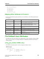
Pre-Defined User Attributes ..................................................................................................... 2-9
array_pin_number (VHDL only) ........................................................................................... 2-9
async_reg (Xilinx) ............................................................................................................... 2-10
block_ram (Xilinx) .............................................................................................................. 2-10
buffer_sig ............................................................................................................................. 2-11
dedicated_mult..................................................................................................................... 2-12
dont_retime .......................................................................................................................... 2-13
dont_touch ........................................................................................................................... 2-13
drive ..................................................................................................................................... 2-14
extract_mac .......................................................................................................................... 2-14
hierarchy .............................................................................................................................. 2-14
inff........................................................................................................................................ 2-15
input_delay (Obsolete)......................................................................................................... 2-15
iob ........................................................................................................................................ 2-16
iostandard............................................................................................................................. 2-16
map_complex....................................................................................................................... 2-17
max_fanout .......................................................................................................................... 2-17
Precision Synthesis Installation Guide, 2003c Update1
March 2004
iii
Table of Contents
Table of Contents (cont.)
nobuff................................................................................................................................... 2-17
nopad.................................................................................................................................... 2-18
outff...................................................................................................................................... 2-18
output_delay (Obsolete)....................................................................................................... 2-19
pad........................................................................................................................................ 2-19
pin_number .......................................................................................................................... 2-19
preserve_driver .................................................................................................................... 2-19
preserve_signal .................................................................................................................... 2-20
preserve_z ............................................................................................................................ 2-20
radhardmethod (Actel) ......................................................................................................... 2-21
safe_fsm ............................................................................................................................... 2-22
slew ...................................................................................................................................... 2-22
synthesis_clearbox ............................................................................................................... 2-23
type_encoding_style ............................................................................................................ 2-23
triff ....................................................................................................................................... 2-23
uselowskewlines .................................................................................................................. 2-24
Chapter 3
Commands
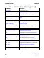
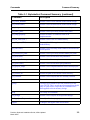
Command Summary ................................................................................................................. 3-1
Functional Command List ..................................................................................................... 3-8
activate_impl ....................................................................................................................... 3-15
add_input_file ...................................................................................................................... 3-16
add_macro_file .................................................................................................................... 3-19
add_placement_file .............................................................................................................. 3-21
alias ...................................................................................................................................... 3-23
all_clocks (SDC).................................................................................................................. 3-24
all_inouts.............................................................................................................................. 3-26
all_inputs (SDC) .................................................................................................................. 3-27
all_outputs (SDC) ................................................................................................................ 3-29
all_registers .......................................................................................................................... 3-31
auto_write ............................................................................................................................ 3-32
close_project ....................................................................................................................... 3-34
close_results_dir .................................................................................................................. 3-35
compile................................................................................................................................. 3-36
copy_impl ............................................................................................................................ 3-37
correlate_reports .................................................................................................................. 3-39
create_clock (SDC).............................................................................................................. 3-40
create_path_definition_set ................................................................................................... 3-44
current_design (SDC) .......................................................................................................... 3-45
current_instance (SDC)........................................................................................................ 3-46
delete_impl........................................................................................................................... 3-47
delete_path_definition_set ................................................................................................... 3-48
iv
Precision Synthesis Installation Guide, 2003c Update1
March 2004
Table of Contents
Table of Contents (cont.)
dofile .................................................................................................................................... 3-49
edit ....................................................................................................................................... 3-50
exec_interactive ................................................................................................................... 3-51
exit ....................................................................................................................................... 3-52
export_settings ..................................................................................................................... 3-53
find ....................................................................................................................................... 3-54
find_clocks........................................................................................................................... 3-57
find_inputs ........................................................................................................................... 3-59
find_outputs ......................................................................................................................... 3-60
get_cells (SDC).................................................................................................................... 3-61
get_clock_domains .............................................................................................................. 3-62
get_clocks (SDC) ................................................................................................................. 3-63
get_designs........................................................................................................................... 3-64
get_false_paths..................................................................................................................... 3-65
get_impl_property................................................................................................................ 3-66
get_lib_cells (SDC).............................................................................................................. 3-67
get_lib_pins (SDC) .............................................................................................................. 3-68
get_libs (SDC) ..................................................................................................................... 3-69
get_multicycle_paths ........................................................................................................... 3-71
get_nets (SDC)..................................................................................................................... 3-72
get_path_definition_set........................................................................................................ 3-74
get_pins (SDC) .................................................................................................................... 3-76
get_ports (SDC) ................................................................................................................... 3-78
get_project_impls................................................................................................................. 3-80
get_project_name................................................................................................................. 3-81
get_results_dir...................................................................................................................... 3-82
get_selected.......................................................................................................................... 3-83
get_version........................................................................................................................... 3-84
group .................................................................................................................................... 3-85
help....................................................................................................................................... 3-87
list_design ............................................................................................................................ 3-88
load_project (Deprecated).................................................................................................... 3-91
logfile ................................................................................................................................... 3-92
move_input_file ................................................................................................................... 3-94
new_impl ............................................................................................................................. 3-95
new_project.......................................................................................................................... 3-96
open_project......................................................................................................................... 3-98
physical_synthesis ............................................................................................................... 3-99
place_and_route ................................................................................................................. 3-101
precision............................................................................................................................. 3-111
remove_attribute ................................................................................................................ 3-114
remove_clock..................................................................................................................... 3-116
remove_clock_latency ....................................................................................................... 3-117
Precision Synthesis Installation Guide, 2003c Update1
March 2004
v
Table of Contents
Table of Contents (cont.)
remove_clock_transition.................................................................................................... 3-118
remove_clock_uncertainty................................................................................................. 3-119
remove_design ................................................................................................................... 3-120
remove_input_delay........................................................................................................... 3-122
remove_input_file .............................................................................................................. 3-124
remove_output_delay......................................................................................................... 3-125
remove_propagated_clock ................................................................................................. 3-127
report_analysis ................................................................................................................... 3-128
report_area ......................................................................................................................... 3-129
report_attributes ................................................................................................................. 3-131
report_connections............................................................................................................. 3-133
report_constraints............................................................................................................... 3-135
report_design_impl_list ..................................................................................................... 3-137
report_input_file_list ......................................................................................................... 3-138
report_io_registers ............................................................................................................. 3-139
report_library ..................................................................................................................... 3-140
report_license..................................................................................................................... 3-142
report_memory_utilization ................................................................................................ 3-143
report_missing_constraints ................................................................................................ 3-144
report_net ........................................................................................................................... 3-146
report_output_file_list ....................................................................................................... 3-148
report_project..................................................................................................................... 3-149
report_technologies............................................................................................................ 3-153
report_timing ..................................................................................................................... 3-154
save_impl ........................................................................................................................... 3-159
save_path_definition_sets .................................................................................................. 3-160
save_physical ..................................................................................................................... 3-161
save_project (Obsolete) ..................................................................................................... 3-162
select .................................................................................................................................. 3-163
set_attribute........................................................................................................................ 3-165
set_clock_latency (SDC) ................................................................................................... 3-167
set_clock_transition (SDC)................................................................................................ 3-169
set_clock_uncertainty (SDC) ............................................................................................. 3-171
set_false_path (SDC) ......................................................................................................... 3-173
set_fanout_load (SDC) ...................................................................................................... 3-178
set_hierarchy_separator ..................................................................................................... 3-179
set_impl_property .............................................................................................................. 3-180
set_input_delay (SDC)....................................................................................................... 3-181
set_input_dir ...................................................................................................................... 3-185
set_input_file ..................................................................................................................... 3-186
set_max_delay (SDC) ........................................................................................................ 3-188
set_max_fanout (SDC) ...................................................................................................... 3-191
set_min_delay (SDC)......................................................................................................... 3-192
vi
Precision Synthesis Installation Guide, 2003c Update1
March 2004
Table of Contents
Table of Contents (cont.)
set_multicycle_path (SDC)................................................................................................ 3-195
set_output_delay (SDC)..................................................................................................... 3-200
set_preference .................................................................................................................... 3-203
set_project_property .......................................................................................................... 3-204
set_propagated_clock (SDC) ............................................................................................. 3-205
set_results_dir .................................................................................................................... 3-206
set_working_dir (Deprecated) ........................................................................................... 3-207
setup_analysis .................................................................................................................... 3-209
setup_design....................................................................................................................... 3-211
setup_place_and_route....................................................................................................... 3-218
synthesize........................................................................................................................... 3-227
tmpfile ................................................................................................................................ 3-228
unalias ................................................................................................................................ 3-229
ungroup .............................................................................................................................. 3-230
update_constraint_file........................................................................................................ 3-232
view_floorplan ................................................................................................................... 3-233
view_schematic.................................................................................................................. 3-234
Chapter 4
How Precision Compiles Designs
How Precision Compiles the Design ........................................................................................ 4-1
Load the Technology Library ................................................................................................ 4-1
Analyzing the Design............................................................................................................. 4-2
Elaborating the Design........................................................................................................... 4-3
Performing Pre-optimization ................................................................................................. 4-6
How Precision Synthesizes the Design..................................................................................... 4-8
Implement operators ............................................................................................................ 4-10
Manipulate Hierarchy .......................................................................................................... 4-10
Bubble Tristates ................................................................................................................... 4-10
How Precision propagates clocks ........................................................................................ 4-10
DRC Resolving .................................................................................................................... 4-11
Adding IO buffers ................................................................................................................ 4-12
Technology mapping ........................................................................................................... 4-12
Determine Critical Paths ...................................................................................................... 4-12
Register Retiming ................................................................................................................ 4-12
Retiming Rules .................................................................................................................... 4-17
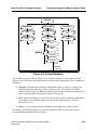
Understanding the In-Memory Design Data Model ............................................................... 4-18
Chapter 5
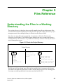
Files Reference
Understanding the Files in a Working Directory...................................................................... 5-1
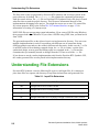
Understanding File Extensions ................................................................................................. 5-2
Precision Synthesis Installation Guide, 2003c Update1
March 2004
vii
Table of Contents
Table of Contents (cont.)
Specifying Output Files ......................................................................................................... 5-4
Precision Initialization File ....................................................................................................... 5-4
Chapter 6
Designing with Actel Devices
Actel Designer Integration ....................................................................................................... 6-1
Setting Actel Designer Options ............................................................................................. 6-3
Handling Actel Design Issues................................................................................................... 6-6
Handling RadHard Designs ................................................................................................... 6-6
Targeting Pipeline Multipliers .................................................................................................. 6-7
Quality of Results and Runtime Improvements for Actel Technologies............................... 6-9
Constraining for Synthesis and Layout..................................................................................... 6-9
Using Synopsys Design Constraints .................................................................................... 6-10
Selecting Military Operating Conditions ............................................................................. 6-11
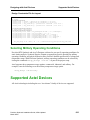
Supported Actel Devices ........................................................................................................ 6-11
Actel Flash Devices Supported............................................................................................ 6-12
Actel Antifuse Devices Supported....................................................................................... 6-13
Actel Mature Products ......................................................................................................... 6-16
Actel Process Derating Factors............................................................................................ 6-19
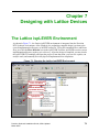
Chapter 7
Designing with Lattice Devices
The Lattice ispLEVER Environment........................................................................................ 7-1
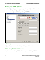
Setting ispLEVER Options .................................................................................................... 7-2
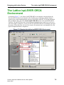
The Lattice ispLEVER ORCA Environment............................................................................ 7-5
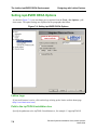
Setting ispLEVER ORCA Options........................................................................................ 7-6
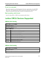
Lattice ORCA Devices Supported ............................................................................................ 7-7
ORCA 2CA Family ............................................................................................................... 7-7
ORCA 2TA Family................................................................................................................ 7-7
ORCA 3C Family .................................................................................................................. 7-8
ORCA 3T Family................................................................................................................... 7-8
ORCA 4E Family................................................................................................................... 7-9
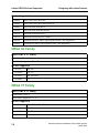
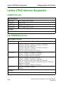
Lattice CPLD Devices Supported........................................................................................... 7-10
ispGDX Devices .................................................................................................................. 7-10
ispLSI5000VE Devices........................................................................................................ 7-10
ispLSI5000VE_UPS Devices .............................................................................................. 7-11
ispmach4000B Devices........................................................................................................ 7-11
ispmach4000C Devices........................................................................................................ 7-11
ispmach5000B Devices........................................................................................................ 7-12
ispmach5000VG Devices .................................................................................................... 7-12
ispXPGA Devices ................................................................................................................ 7-12
ispXPLD5000MX Devices .................................................................................................. 7-13
viii
Precision Synthesis Installation Guide, 2003c Update1
March 2004
Table of Contents
Table of Contents (cont.)
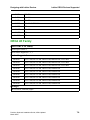
MACH Devices.................................................................................................................... 7-13
pLSI-1000 Devices .............................................................................................................. 7-14
pLSI-2000 Devices .............................................................................................................. 7-14
pLSI-3000 Devices .............................................................................................................. 7-16
Chapter 8
Designing with Altera Devices
Handling Altera Design Issues ................................................................................................. 8-1
Mapping Registers to IO Blocks............................................................................................ 8-1
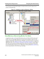
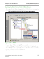
Assigning an Altera LogicLock Region to a Block ............................................................... 8-1
How Memory Inferencing Works for Altera ......................................................................... 8-2
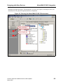
Altera MAX+PLUS II Integration............................................................................................ 8-4
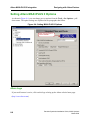
Setting Altera MAX+PLUS II Options ................................................................................. 8-6
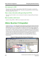
Altera Quartus II Integration..................................................................................................... 8-8
Quartus II v2.X and v3.0 Support.......................................................................................... 8-9
Setting Altera Quartus II Options .......................................................................................... 8-9
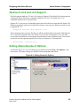
Using Altera Megafunction Blocks ..................................................................................... 8-10
Altera Devices Supported ....................................................................................................... 8-12
Stratix Hardcopy Support .................................................................................................... 8-12
StratixGX Devices Supported.............................................................................................. 8-13
Cyclone Devices Supported................................................................................................. 8-13
Stratix Devices Supported ................................................................................................... 8-13
Excalibur Arm Devices Supported ...................................................................................... 8-14
Mercury Devices Supported ................................................................................................ 8-15
APEX II Devices Supported ................................................................................................ 8-15
APEX 20KC Devices Supported ......................................................................................... 8-16
APEX 20KE Devices Supported ......................................................................................... 8-16
APEX 20K Devices Supported............................................................................................ 8-17
FLEX 10K Devices Supported ............................................................................................ 8-17
FLEX 6000/8000 Devices Supported .................................................................................. 8-19
ACEX Devices Supported ................................................................................................... 8-19
MAX Family Devices Supported ........................................................................................ 8-20
Chapter 9
Designing with Xilinx
Handling Xilinx Design Issues ................................................................................................. 9-1
Handling Clock Resources..................................................................................................... 9-1
Working with UCF files ........................................................................................................ 9-2
Including Xilinx Coregen-Generated Modules...................................................................... 9-3
Mapping Registers to IO Blocks............................................................................................ 9-8
Xilinx Memory Mapping ....................................................................................................... 9-8
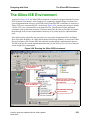
The Xilinx ISE Environment .................................................................................................. 9-31
Precision Synthesis Installation Guide, 2003c Update1
March 2004
ix
Table of Contents
Table of Contents (cont.)
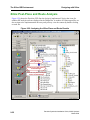
Xilinx Post-Place and Route Analysis ................................................................................. 9-32
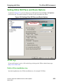
Setting Xilinx ISE Place and Route Options ....................................................................... 9-33
Setting Xilinx ISE Constraint File Options ......................................................................... 9-35
Xilinx Devices Supported ....................................................................................................... 9-36
Virtex-II Pro Devices Supported ......................................................................................... 9-36
Virtex-II Devices Supported .............................................................................................. 9-37
Virtex-E Devices Supported ................................................................................................ 9-38
Virtex Devices Supported .................................................................................................... 9-38
Spartan-III Devices Supported............................................................................................. 9-39
Spartan-IIE Devices Supported ........................................................................................... 9-39
Spartan-II Devices Supported .............................................................................................. 9-40
Xilinx CPLD Family Devices Supported ............................................................................ 9-40
x
Precision Synthesis Installation Guide, 2003c Update1
March 2004
Table of Contents
List of Figures
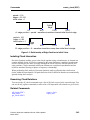
Figure 3-1. Relationship of Edge Position to Initial Value.................................................... 3-43
Figure 3-2. Hierarchical Pins ............................................................................................... 3-176
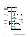
Figure 3-10. Multicycle Timing........................................................................................... 3-198
Figure 4-1. Reading Your Input Design .................................................................................. 4-1
Figure 4-2. Constant Propagation Example ............................................................................. 4-7
Figure 4-3. Resource Sharing Results...................................................................................... 4-8
Figure 4-4. A Binary Decision Diagram.................................................................................. 4-9
Figure 4-5. Simple Circuit before Retiming. Slack = -0.44 ns. ............................................ 4-14
Figure 4-6. Simple Circuit after Retiming. Slack = 0.55 ns. ................................................ 4-14
Figure 4-7. Enabling the Register Retiming Algorithm ........................................................ 4-15
Figure 4-8. Reset Signal Changes to Preset ........................................................................... 4-17
Figure 4-2. Design Database.................................................................................................. 4-19
Figure 5-1. Files in the Project Directory ................................................................................ 5-1
Figure 5-2. Hierarchical Project File Structure........................................................................ 5-4
Figure 6-1. Running the Actel Designer Environment ............................................................ 6-2
Figure 6-2. Setting Actel Designer Options ............................................................................ 6-3
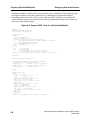
Figure 6-3. Sample VHDL Code for a Pipelined Multiplier ................................................... 6-8
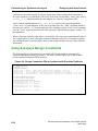
Figure 6-4. Design Constraints File for Synthesis with Precision Synthesis......................... 6-10
Figure 7-1. Running the Lattice ispLEVER Environment ...................................................... 7-1
Figure 7-2. Setting Lattice ispLEVER Options ....................................................................... 7-2
Figure 7-3. Running the Lattice ispLEVER ORCA Environment .......................................... 7-5
Figure 7-4. Setting ispLEVER ORCA Options ....................................................................... 7-6
Figure 8-1. Assigning a LogicLock Region to a Block ........................................................... 8-2
Figure 8-2. Specifying the Block Size for Stratix TriMatrix Memory .................................... 8-3
Figure 8-3. Running the Altera MAX+PLUS II Environment ................................................ 8-5
Figure 8-4. Setting MAX+PLUS II Options............................................................................ 8-6
Figure 8-5. Running the Altera Quartus II Environment......................................................... 8-8
Figure 8-6. Setting Quartus II Options .................................................................................... 8-9
Figure 8-7. Excluding the Implementation File from the Compile Phase ............................. 8-11
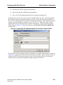
Figure 8-8. Successful place and route .................................................................................. 8-12
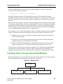
Figure 9-1. Coregen Files ........................................................................................................ 9-3
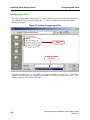
Figure 9-2. Adding Coregen input files ................................................................................... 9-4
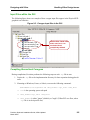
Figure 9-3. .Coregen input files in the GUI ............................................................................. 9-5
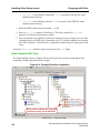
Figure 9-4. Coregen files after compilation............................................................................. 9-6
Figure 9-5. Coregen files after compilation............................................................................. 9-7
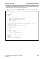
Figure 9-6. Inferring Xilinx Single-Port RAM from VHDL ................................................... 9-9
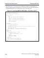
Figure 9-7. Inferring Xilinx Single-Port RAM from Verilog ................................................ 9-10
Figure 9-8. Using the Precision GUI to Direct the Mapping of Memory.............................. 9-11
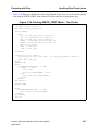
Figure 9-9. Inferring Xilinx Dual-Port RAM from VHDL ................................................... 9-12
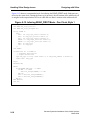
Figure 9-10. Inferring Xilinx Dual-Port RAM from Verilog ................................................ 9-13
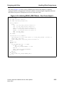
Figure 9-11. Inferring WRITE_FIRST Mode - One Clock, Style 1...................................... 9-14
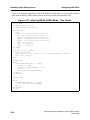
Figure 9-12. Inferring WRITE_FIRST Mode - One Clock, Style 2...................................... 9-15
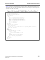
Figure 9-13. Inferring WRITE_FIRST Mode - One Clock, Style 3...................................... 9-16
xi
Precision Synthesis Installation Guide, 2003c Update1
March 2004
Table of Contents
List of Figures (cont.)
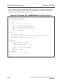
Figure 9-14.
Figure 9-15.
Figure 9-16.
Figure 9-17.
Figure 9-18.
Figure 9-19.
Figure 9-20.
Figure 9-21.
Figure 9-22.
Figure 9-23.
Figure 9-24.
Figure 9-25.
Figure 9-26.
Figure 9-27.
Figure 9-28.
Figure 9-29.
Figure 9-30.
Figure 9-31.
xii
Inferring WRITE_FIRST Mode - Two Clocks................................................. 9-17
Inferring READ_FIRST Mode - One Clock, Style 1........................................ 9-18
Inferring READ_FIRST Mode - One Clock, Style 2........................................ 9-19
Inferring READ_FIRST Mode - Two Clocks................................................... 9-20
Inferring NO_CHANGE Mode - One Clock, Style 1 ....................................... 9-21
Inferring NO_CHANGE Mode - One Clock, Style 2 ....................................... 9-22
Inferring NO_CHANGE Mode - Two Clocks .................................................. 9-23
Tri-Port RAM Sync Write, Sync Read, Sync Read, One Clock ....................... 9-24
Tri-Port RAM Sync Write, Sync Read, Sync Read, Two Clocks..................... 9-25
Tri-Port RAM Sync Write/Async Read, Async Read, Async Read ................. 9-26
Tri-Port RAM Sync Read/Write, Sync Read, Sync Read................................. 9-27
Tri-Port RAM Sync Read Write, WRITE_FIRST Mode ................................. 9-28
Tri-Port RAM Port A Sync Read Write - READ_FIRST Mode ...................... 9-29
Tri-Port RAM Port A Sync Read Write - NO_CHANGE Mode...................... 9-30
Running the Xilinx ISE Environment ............................................................... 9-31
Analyzing the Xilinx Place and Route Results ................................................. 9-32
Setting Xilinx ISE Place and Route Options .................................................... 9-33
Setting Xilinx ISE Constraint File Options....................................................... 9-35
Precision Synthesis Installation Guide, 2003c Update1
March 2004
Table of Contents
List of Tables
Table 2-1. Alphabetical Attribute Summary ............................................................................ 2-1
Table 2-2. Module Attributes ................................................................................................... 2-4
Table 2-3. I/O Port Attributes ................................................................................................. 2-4
Table 2-4. Net Attributes ......................................................................................................... 2-5
Table 2-5. dedicated_multi attributes .................................................................................... 2-12
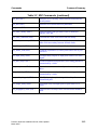
Table 3-1. Alphabetical Command Summary ......................................................................... 3-1
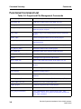
Table 3-2. Project and File Management Commands .............................................................. 3-8
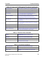
Table 3-4. Constraint Commands ............................................................................................ 3-9
Table 3-3. Synthesis Flow Commands .................................................................................... 3-9
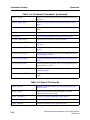
Table 3-5. Report Commands ................................................................................................ 3-10
Table 3-6. Object Access Commands .................................................................................... 3-11
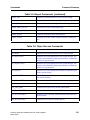
Table 3-7. SDC Commands ................................................................................................... 3-12
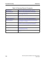
Table 3-8. Precision Physical Commands ............................................................................. 3-14
Table 3-9. File Format mapping for auto_write command .................................................... 3-32
Table 4-1. Technologies Supported by Register Retiming .................................................... 4-13
Table 5-1. Input File Extensions ............................................................................................. 5-2
Table 5-2. Precision-Specific Files .......................................................................................... 5-3
Table 5-3. Output File Extensions .......................................................................................... 5-3
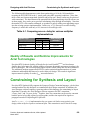
Table 6-1. Comparing area vs. delay for various multiplier implementations ........................ 6-9
Precision Synthesis Installation Guide, 2003c Update1
March 2004
xiii
Table of Contents
List of Tables (cont.)
xiv
Precision Synthesis Installation Guide, 2003c Update1
March 2004
Chapter 1
Introduction
Invoking Precision Synthesis
Invoking the Graphical User Interface
You invoke the PrecisionTM RTL Synthesis GUI with the precision command. You invoke the
PrecisionTM Physical Synthesis GUI with the precision -physical command. Other optional
command switches allow you to customize the invocation. The precision command usage is
fully documented in the section titled Commands starting on page 3-1
Invoking Precision Synthesis from a Shell
You can invoke Precision RTL Synthesis in non-GUI mode by using the command precision shell. You can invoke Precision Physical Synthesis in non-GUI mode by using the command
precision -shell -physical.In this mode you can source Tcl scripts or you can interactively enter
commands from the shell prompt. The details about using the precision command are
documented in the section titled Commands starting on page 3-1.
Precision Synthesis Installation Guide, 2003c Update1
March 2004
1-1
The Tcl Command Interface
Introduction
The Tcl Command Interface
The Precision Synthesis Graphical User Interface is based on the Tcl language. Standard Tcl
Commands provide a foundation for the command structure. Precision Synthesis Tcl command
extensions provide the major synthesis processing power. You can exercise further control over
the process when you set constraints and attributes on design objects. For example, you can set
an input delay constraint on an input port to specify how much of the clock cycle is consumed
outside the chip before the signal arrives. In another example, you can specify a dont_touch
attribute on a block (possibly an IP block) to prevent the block from being optimized during
synthesis. You will set most constraints and attributes by right-clicking on objects in the GUI
and selecting a menu item. In this case, you select Don’t Touch from the menu.
Standard Tcl Commands
Precision Synthesis accepts all standard commands of the Tcl language. Tcl supports commands
that include: variable assignment, handling of lists and arrays, sorting, string manipulation,
arithmetic operations, (if/case/foreach/while) statements, and procedures.
Precision Synthesis Tcl Commands
Mentor Graphics has added a number of command extensions to the Tcl language to handle and
support the synthesis process. These commands are “built-in” and are executed the same as the
standard Tcl commands.
Setting Attributes
An attribute is information that is attached to (owned by) an object in the Precision Synthesis inmemory design database. The ability to set attributes gives you a mechanism to control and fine
tune the synthesis process.
An attribute has a name, a type, a value, and an owner. An attribute’s value typically describes a
characteristic about the design object.
The concept of an attribute in an HDL language is the same. The attribute is a name/value pair
that is associated with, (“attached to”, “set on”, or “owned by”) a design object in the design. In
VHDL, the attribute construct may be used to associated a design object with an attribute
value and in Verilog, a //pragma attribute directive may be used. If these attributes are
declared in the source files, the HDL attributes are converted to attributes in the in-memory
database and many time are translated as EDIF properties during an EDIF netlisting operation.
You can attach an attribute to an in-memory design object by using the set_attribute command
in the interactive command line window. Executing the remove_attribute command removes
the attribute. Sometimes setting a variable also sets the associated attribute.
1-2
Precision Synthesis Installation Guide, 2003c Update1
March 2004
Introduction
The Tcl Command Interface
Methods for Using Commands With a Tcl Script
After you create a Tcl script, you can source your Tcl script from Precision Synthesis as
follows:
•
The Interactive Command Line Shell
•
The GUI Menu Bar File -> Run Script
•
The Shell Command Line with a Path to Precision Synthesis
Note: The Precision Synthesis .log file is a Tcl script file that you can use after making the
necessary edits. You can also generate a Tcl command file by right-clicking in the Transcript
window and selecting Save Command File.
Interactive Command Line Shell
Type the following syntax to source your Tcl script:
source <my_tcl_script>
or type the following command to execute your Tcl script:
dofile <my_tcl_script>
The dofile command is similar to the source command in that it executes the Tcl commands
that are specified in the file. In addition, dofile sends a message to the standard output device
each time a Tcl command is executed. This is an excellent tool that you can use to help debug
the Tcl script.
GUI Menu Bar File -> Run Script
On the menu bar click on File -> Run Script. Type in your Tcl script name or click on the
button and choose a Tcl script file. Your script file runs in the GUI Information window.
Command Line with Path to Precision Synthesis
Bring up your PC or UNIX window. Type the appropriate argument to source your Tcl script:
For Precision RTL Synthesis:
<precision install directory>/bin/precision -shell -file <my_tcl_script>
For Precision Physical Synthesis:
<precision install directory>/bin/precision -shell -physical -file <script>
Precision Synthesis Installation Guide, 2003c Update1
March 2004
1-3
The Tcl Command Interface
Introduction
Command Line Description
Command and Option Abbreviation
Precision Synthesis allows abbreviated Tcl commands: you only need to spell out a command
until the command meaning is unambiguous.
For example, the command syn executes the synthesize command. If the command is still
ambiguous, Precision Synthesis produces an error message. For example, the command
current displays the following:
ambiguous command name “current”: current_design current_instance
The Precision Synthesis commands also allow abbreviated options: you do not need to type the
options in full; only type the part that makes the option unambiguous.
For example, all_clocks -i enables the -internal option for the all_clocks command.
Aliasing
Precision Synthesis offers an alias command, which allows you to define your own name for
commonly used command strings. For example, if you frequently need to know what clock
constraints are missing, then you may want to write an alias:
alias rmc {report_missing_constraints -clock}
If you now type the command rmc, Precision Synthesis executes the command
{report_missing_constraints -clock}.
Command Line Help
You can display information about commands by using the help command. The help command
uses a regular expression (a name with or without wildcards), and prints usage for commands
that match the regular expression. For example, you can type help * to bring up a transcript
list of all commands. Typing help report* displays information about all commands that start
with the string report.
Also, every command takes -help switch as an option.
setup_design -help
is the same as:
help setup_design
1-4
Precision Synthesis Installation Guide, 2003c Update1
March 2004
Introduction
The Tcl Command Interface
Tcl Scripting Language
Precision Synthesis accepts all commands of the Tcl language. Tcl supports commands that
include: variable assignment, handling of lists and arrays, sorting, string manipulation,
arithmetic operations, (if/case/foreach/while) statements, and procedures. Tcl is VERY handy
for writing scripts for Precision Synthesis.
The Tcl command, source <my_tcl_script>, enables you to source (execute) script files from
Precision Synthesis, or from within other script files. This feature allows you to write
customized (portions of) design flows, or any other sequence of commands that you may want
to execute.
A feature inherited from Tcl is autoexec: all UNIX (and many DOS) commands available
from your path can be run from the Precision Synthesis command line. Another helpful Tcl
feature is history tracking. Type the command history to view your previous commands. Any
previous command can be re-executed using !NUMBER, or !! for re-execution of the last
command.
Automatically Running a Tcl Startup Script on Invocation
If you place a Tcl script file named .precision.tcl in your home directory ($HOME) on Unix
or in your user profile folder in Windows (C:\documents and Settings\<username>), then
Precision Synthesis will first read and execute the commands in that file each time the tool is
invoked. This is a handy way for you to automatically define frequently used aliases and Tcl
procedures. And, because this file is in your home directory, you can update your Precision
Synthesis software tree without overwritting this file.
Command Syntax Definitions
The command list character symbols are defined as follows:
•
[ ] optional arguments
•
< > fields to be completed with your names
•
| “or” symbol indicates mutually exclusive arguments
In the read command the add_input_file <file_pathname(s)> field is replaced with your
file pathname(s). For example: add_input_file {fsm.vhd datapath.vhd top.vhd}. In this
case, only the file leaf names are specified, so the files are assumed to be in the current working
directory.
You should always use the forward slash character (/) to separate directory names in a path,
even on the PC. Precision Synthesis interprets the back slash character (\) as a Tcl escape
character.
Precision Synthesis Installation Guide, 2003c Update1
March 2004
1-5
The Design Data Model
Introduction
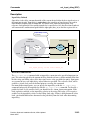
Precision Synthesis turns your HDL code into an in-memory design data base while Schematic
Viewing provides a tool for exploring and interacting with this design data base. The following
section provides a brief tour of the design database and describes methods for using commands
on the interactive Command Line Shell.
The Design Data Model
The Precision Synthesis in-memory design data base is modeled after the EDIF design data
model. All design data is stored in a set of EDIF-type libraries which start at the root. A library
contains a list of cells, and a cell contains a list of views. In comparison to VHDL, a cell is
equivalent to an ENTITY and a view is equivalent to an architecture. Just as most VHDL
entities have only one architecture, most cells have only one view. Views are the basic building
blocks of your design and are equivalent to a schematic sheet. A view can have three types of
objects, ports, nets, and instances. A view is the implementation or contents of a single level of
hierarchy.
Examples:
•
•
•
•
When you read a VHDL description into Precision Synthesis, your VHDL entity
translates to a cell, and the VHDL architecture (contents) translates to a view. By
default, the cell is stored in an EDIF-style library called work (by default). You can
change the name of this library if you wish.
When you load a technology library into Precision Synthesis, it becomes an EDIF-type
library in the design database, which contains all of the cells of that technology. Your
design in the work library will reference this technology library as an external EDIF
library.
Precision Synthesis creates an EDIF style library of PRIMITIVES automatically. This
library represents all primitive logic functions that Precision Synthesis may require
when compiling or elaborating HDL (VHDL and Verilog) descriptions.
Precision Synthesis also automatically creates an OPERATORS library. This library
contains operator cells (adders, multipliers, muxes). When compiling HDL descriptions,
these operators are generated when needed.
In summary, the following objects are typically contained within a view and are used to
represent netlists and hierarchies in a design:
1-6
•
A view has ports, nets and instances.
•
A port is a terminal of a view.
•
An instance is a pointer to a view.
Precision Synthesis Installation Guide, 2003c Update1
March 2004
Introduction
•
The Design Data Model
A net is a connection between ports and/or port instances (pointer to the port of the view
under an instance).
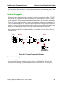
The following code example is a small VHDL description that represents a primitive AND
function:
entity and2 is
port (a,b: bit; o:out bit);
end and2;
architecture contents of and2 is
begin
o <= a AND b;
end contents;
Precision Synthesis then creates a cell called and2 in the default library work. The cell contains
a view, called contents. The view contains three ports: a, b and o. The view also contains an
instance of a view in the Precision Synthesis PRIMITIVES library. This is an instance of a
primitive AND. The name of the instance is created by Precision Synthesis. The view also
contains three nets: a, b, and o, connecting the instance to the ports of the view. All objects
libraries, cells, views, ports, nets and instances can contain attributes.
Precision Synthesis Installation Guide, 2003c Update1
March 2004
1-7
The Design Data Model
1-8
Introduction
Precision Synthesis Installation Guide, 2003c Update1
March 2004
Chapter 2
Attributes
An attribute is information that is attached to (owned by) an object in the Precision Synthesis inmemory design database. An attribute has a name, a type, a value, and an owner. An attribute’s
value typically describes a characteristic about the design object.
The concept of an attribute in an HDL language is the same. The attribute is a name/value pair
that is associated with, (“attached to”, “set on”, or “owned by”) a design object in the design. In
VHDL, the attribute construct may be used to associated a design object with an attribute
value and in Verilog, a //pragma attribute directive may be use. If these attributes are
declared in the source files, the HDL attributes are converted to attributes on objects in the inmemory database and may be translated as EDIF properties during an EDIF netlisting operation
and/or passed to the vendor’s implementation software via a user constraint file.
In Precision Synthesis, setting attributes is used as a control mechanism to guide the synthesis
process. The syntax and methods for applying attributes to your in-memory design are
described in this chapter.
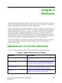
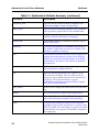
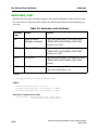
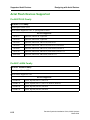
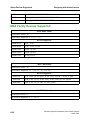
Alphabetical List of User Attributes
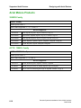
Table 2-1 contains a summary of the User attributes that Precision Synthesis supports.
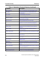
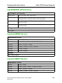
Table 2-1. Alphabetical Attribute Summary
Attribute
Description
array_pin_number (VHDL only)
This VHDL only attribute makes it easier to assign pin
numbers to buses.
async_reg (Xilinx)
Allows you to specify an asynchronous registration
flow. This attribute is used in Xilinx to flag flip-flops as
clock domain-crossing flops for gate-level simulation.
block_ram (Xilinx)
Allows you to disable the mapping of a particular RAM
instance to block RAM in Xilinx technologies.
buffer_sig
Specifies that a signal (a net) in the design is to be
buffered with a technology-specific buffer.
Precision Synthesis Installation Guide, 2003c Update1
March 2004
2-1
Alphabetical List of User Attributes
Attributes
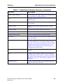
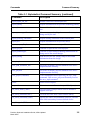
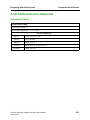
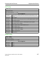
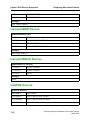
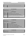
Table 2-1. Alphabetical Attribute Summary [continued]
Attribute
Description
dedicated_mult
Specifies that an instance should be mapped to the
dedicated multiplier resource in place/route.
dont_retime
Specifies that the Retiming algorithm can be disabled
on a register-by-register basis or on a module basis.
dont_touch
Tells Precision Synthesis to pass the module through
synthesis without optimizing or unmapping.
extract_mac
Controls the mapping of multiply-accumulate logic to
Altera DSP blocks.
hierarchy
Tells Precision Synthesis to maintain the hierarchy of
the module. Valid values are preserve or flatten. This
attribute is applied to instances.
inff
Tells Precision Synthesis whether or not to map the first
register in the input path to a register in the IOB. By
default, Precision maps the first register to the IOB if
this attribute is not present. The attribute is applied to
the input port.
input_delay (Obsolete)
This attribute is no longer supported. An input delay is
now specified as a timing constraint.
iob
Specifies that the placement of the register is to be
forced into the IO block. This may increase the IO
frequency at the possible expense of the internal chip
frequency. For bi-directional ports, you can
individually control the movement of flops using the
inff, outff, and triff attributes.
max_fanout
Allows you to change the fanout limit on the specified
net.
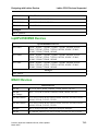
nobuff
Prevents the specified signal from being buffered.
nopad
Prevents the placement of an I/O pad on the specified
port when the design is mapped to the technology.
outff
Tells Precision Synthesis whether or not to map the
candidate register in the output path to a register in the
IOB. By default, Precision maps the register to the IOB
if this attribute is not present. The attribute is applied to
the output port.
2-2
Precision Synthesis Installation Guide, 2003c Update1
March 2004
Attributes
Alphabetical List of User Attributes
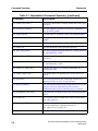
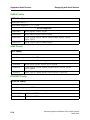
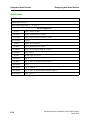
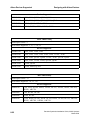
Table 2-1. Alphabetical Attribute Summary [continued]
Attribute
Description
output_delay (Obsolete)
This attribute is no longer supported. An output delay is
now specified as a timing constraint.
pad
Specifies which technology-specific I/O cell to used for
a specific port.
pin_number
Assigns a specific device pin number to a specific port
in the design.
preserve_driver
Preserves the specified signal and the driver in the
design.
preserve_signal
Preserves the specified signal in the design.
preserve_z
Prevents tri-states from being mapped to MUX logic.
radhardmethod (Actel)
Creates a radiation hardened implementation.
safe_fsm
Specifies that the Finite State Machine should be built
as a “safe” FSM.
synthesis_clearbox
Specifies that Precision should generate timing models
for Altera blackboxes using Altera’s clearbox timing
generator. This will have a noticeable affect on runtime
but it provides more accurate timing reports. This
attribute can be applied to the top of the design or to
individual hierarchical blocks.
type_encoding_style
Specifies the style of encoding for a Finite State
Machine.
triff
Tells Precision Synthesis whether or not to map the
candidate register in the path to a register in the IOB.
By default, Precision maps the register to the IOB if this
attribute is not present. The attribute is applied to the
inout port.
uselowskewlines
Tells the implementation tools to assign the specified
signal to a low skew route line.
Precision Synthesis Installation Guide, 2003c Update1
March 2004
2-3
Functional Lists of User Attributes
Attributes
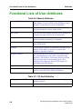
Functional Lists of User Attributes
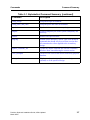
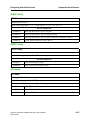
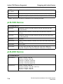
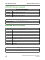
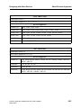
Table 2-2. Module Attributes
async_reg (Xilinx)
Allows you to specify an asynchronous registration flow.
This attribute is used in Xilinx to flag flip-flops as clock
domain-crossing flops for gate-level simulation.
dedicated_mult
Specifies that an instance should be mapped to the
dedicated multiplier resource in place/route.
dont_retime
Specifies that the Retiming algorithm can be disabled on
a register-by-register basis or on a module basis.
dont_touch
Tells Precision Synthesis to pass the module through
synthesis without optimizing or unmapping.
extract_mac
Controls the mapping of multiply-accumulate logic to
Altera DSP blocks.
hierarchy
Tells Precision Synthesis to maintain the hierarchy of the
module. Valid values are preserve or flatten. This
attribute is applied to instances.
synthesis_clearbox
Specifies that Precision should generate timing models
for Altera blackboxes using Altera’s clearbox timing
generator. This will have a noticeable affect on runtime
but it provides more accurate timing reports. This
attribute can be applied to the top of the design or to
individual hierarchical blocks.
radhardmethod (Actel)
Creates a radiation hardened implementation.
block_ram (Xilinx)
Allows you to disable the mapping of a particular RAM
instance to block RAM in Xilinx technologies.
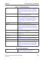
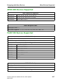
Table 2-3. I/O Port Attributes
array_pin_number (VHDL only)
This VHDL only attribute makes it easier to assign pin
numbers to buses.
drive
Sets the value to be associated with a drive.
2-4
Precision Synthesis Installation Guide, 2003c Update1
March 2004
Attributes
Functional Lists of User Attributes
Table 2-3. I/O Port Attributes
inff
Tells Precision Synthesis whether or not to map the first
register in the input path to a register in the IOB. By
default, Precision maps the first register to the IOB if this
attribute is not present. The attribute is applied to the
input port.
input_delay (Obsolete)
This attribute is no longer supported. An input delay is
now specified as a timing constraint.
iob
Specifies that the placement of the register is to be forced
into the IO block. This may increase the IO frequency at
the possible expense of the internal chip frequency. For
bi-directional ports, you can individually control the
movement of flops using the inff, outff, and triff
attributes.
iostandard
Specifies the IO standard to be used.
outff
Tells Precision Synthesis whether or not to map the
candidate register in the output path to a register in the
IOB. By default, Precision maps the register to the IOB if
this attribute is not present. The attribute is applied to the
output port.
output_delay (Obsolete)
This attribute is no longer supported. An output delay is
now specified as a timing constraint.
pad
Specifies which technology-specific I/O cell to used for a
specific port.
pin_number
Assigns a specific device pin number to a specific port in
the design.
preserve_z
Prevents tri-states from being mapped to MUX logic
slew
Specifies the slew value.
triff
Tells Precision Synthesis whether or not to map the
candidate register in the path to a register in the IOB. By
default, Precision maps the register to the IOB if this
attribute is not present. The attribute is applied to the
inout port.
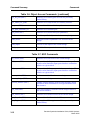
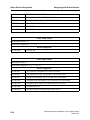
Table 2-4. Net Attributes
buffer_sig
Specifies that a signal (a net) in the design is to be
buffered with a technology-specific buffer.
Precision Synthesis Installation Guide, 2003c Update1
March 2004
2-5
How to Set Attributes
Attributes
Table 2-4. Net [continued]Attributes
dedicated_mult
Specifies that an instance should be mapped to the
dedicated multiplier resource in place/route.
extract_mac
Controls the mapping of multiply-accumulate logic to
Altera DSP blocks.
max_fanout
Allows you to change the fanout limit on the specified
net.
nobuff
Prevents the specified signal from being buffered.
nopad
Prevents the placement of an I/O pad on the specified
port when the design is mapped to the technology.
preserve_driver
Preserves the specified signal and the driver in the
design.
preserve_signal
Preserves the specified signal in the design.
radhardmethod (Actel)
Creates a radiation hardened implementation.
uselowskewlines
Tells the implementation tools to assign the specified
signal to a low skew route line.
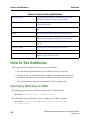
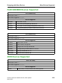
How to Set Attributes
This section provides examples of various ways to set attributes.
1. You can declare and set attributes in your VHDL or Verilog source files
2. You can use the set_attribute and remove_attribute commands in the Interactive
Command Line Shell to set and remove attributes on in-memory design objects
3. You can set attributes using a Precision Synthesis SDC constraint file
Specifying Attributes in VHDL
The following syntax can be used for the declaration of a VHDL attribute:
attribute <attribute_name> : <attribute_type> ;
The following syntax describes how to set an attribute on a VHDL component.
attribute <attribute_name> of <object_name> : component is
<attribute_value>
2-6
Precision Synthesis Installation Guide, 2003c Update1
March 2004
Attributes
How to Set Attributes
Note: Set on component which is corresponding to view.
attribute <attribute_name> of <object_name> : label is <attribute_value>
Note: Set on a label which is corresponding to an instance.
VHDL Example:
entity example is
port ( inp, clk : in std_logic;
outp : out std_logic;
inoutp : inout std_logic;
) ;
attribute buffer_sig : string ;
attribute buffer_sig of clk:signal is “CLOCK BUFFER”;
end example;
All Precision attributes are defined in the mgc_attributes package file at
$MGC_HOME/pkgs/techdata/vhdl/mgc_attr.vhd. You can either use this file as examples for
defining attributes in your design or reference this file in your VHDL code. Precision
automatically reads this file during ‘compile’.
USE work.mgc_attributes.all;
Specifying Attributes in Verilog
Use the following directive for Verilog attributes.
//pragma attribute <object_name> <attribute_name> <attribute_value>
Verilog Example:
//example
module expr (a, b, c, out1, out2);
input [15:0] a, b, c;
output [15:0] out1, out2;
assign out1 = a + b;
assign out2 = b + c;
//pragma attribute expr dont_touch true
endmodule
In this example, the “fastest” Precision Synthesis modgen + operator is used for the out1
assignment.
Precision Synthesis Installation Guide, 2003c Update1
March 2004
2-7
How to Set Attributes
Attributes
Specifying Attributes on the Command Line or in
scripts
Sometimes it is desirable to avoid setting attributes in the HDL source files and instead set
attributes by sourcing a Tcl script or typing a command directly from the Interactive Command
Line Shell. You can use the set_attribute command to add an attribute to an in-memory
design object and the remove_attribute command to remove an attribute.
You can use the following Tcl syntax, for example, if you do not want to modify your Verilog or
VHDL code:
set_attribute -<obj_type> <obj_name> -name <attribute_name> -value
<attribute_value>
Interactive Command Line Shell Example:.
set_attribute -instance abc -name noopt -type boolean
-value TRUE
remove_attribute -instance abc -name noopt
where: -type is [boolean, string, array] etc.
Specifying Attributes using the -design Switch
When running the Precision tool, you can specify whether you want attributes applied to the
RTL design or to the gatelevel technology view. Before synthesis, the tool applies information
only to the RTL design. After synthesis, the tool creates a technology gatelevel view.
To indicate that you want attributes applied to the RTL or gatelevel view, you must include the
-design switch and indicate RTL or gatelevel.
•
-design <rtl | gatelevel>
Tells the tool whether to look for the object in the RTL or the gatelevel view.
The following example indicates that set_attribute switches should be applied to the gatelevel
view.
set_attribute -design gatelevel -instance abc -name noopt -type boolean
-value TRUE
The -design switch applies to the following commands:
report_attributes
report_constraints
set_attribute
set_clock_latency
2-8
Precision Synthesis Installation Guide, 2003c Update1
March 2004
Attributes
Pre-Defined User Attributes
set_clock_transition
set_clock_uncertainty
set_false_path
set_input_delay
set_max_delay
set_min_delay
set_multicycle_path
Mapping Other Attributes to Precision
Precision automatically maps other attributes to it’s predefined set. The following table shows
this mapping:
Attribute
Precision Attribute
Description
Syn_keep
Preserve_signal
A combinatorial signal is defined by this attribute so that this
signal is not optimized out during synthesis
Syn_preserve
Preserve_driver
A registered-signal is defined by this attribute so that this
signal is not optimized out during synthesis
Syn_maxfan
Max_fanout
Syn_useioff
Inff, outff, triff
Specifies to use I/O flip-flops to improve timings.
Syn_useenables
Use_dffenables
Prevents generation of registers with clock enables
Syn_hier
hierarchy
Specifies in HDL code about the way the compiler should
handle hierarchy
Syn_encoding
encoding
Explicitly defines FSM encoding
Sets an individual input port or register output fanout limit in
the HDL code
Pre-Defined User Attributes
The following is a list of pre-defined User attributes that you can set from the Verilog or VHDL
source code, a Tcl script, or by using the Interactive Command Line Shell once the design is
read into memory.
array_pin_number (VHDL only)
This VHDL only attribute makes it easier to assign pin numbers to buses.
VHDL Example:
entity sync_ram is
port (data_in : in UNSIGNED(7 downto 0);
address : in UNSIGNED(15 downto 0);
we
: in std_logic;
Precision Synthesis Installation Guide, 2003c Update1
March 2004
2-9
Pre-Defined User Attributes
Attributes
clk
: in std_logic;
data_out : in UNSIGNED(7 downto 0));
type mentor_string_array is array (natural range <>, natural range <>) of
character ;
attribute array_pin_number : mentor_string_array ;
attribute array_pin_number of data_out:signal is
(“H2”,”H4”,”E4”,”P1”,”C1”,”D5”,”C4”,”A8”);
end sync_ram;
In the above example, the pin numbers are assigned left to right. H2 is assigned to data_out(7),
H4 is assigned to data_out(6), and so on.
async_reg (Xilinx)
Allows you to specify an asynchronous registration flow. This attribute is used in Xilinx to flag
flip-flops as clock domain-crossing flops for gate-level simulation.
This is a simulation enhancement that lets you specify a signal/flip-flop as being a “clock
domain-crossing” flip flop. This would require that there is already proper metastability
protection circuitry in place, and setup/hold checks can be disabled for that particular flop such
that an X is never propogated from that flip-flop. The ASYNC_REG flows can be entered as a
TCL constraint or a VHDL label.
TCL Constraint Example:
# Setting attributes in a constraint file
set_attribute -name ASYNC_REG -value TRUE -instance reg_resync_fifo_full
VHDL Example:
Setting the attribute on a flop instantiation through a VHDL attribute
attribute async_reg : string;
attribute async_reg of U1_resync_fifo_full: label is "true";
block_ram (Xilinx)
Allows you to disable the mapping of a particular RAM instance to block RAM in Xilinx
technologies.
Block RAMs are highly area efficient because they use dedicated on-chip resources, but may
result in additional delay. The use of Block RAMs can cause timing problems in two areas.
First, the clock to out path of a Block RAM is roughly 20% slower than the equivalent
Distributed RAM implementation. Second, Block RAMs must be placed in specific areas of the
Xilinx Virtex II die. If you use block RAMs, check the post-layout timing reports in Xilinx to
insure that poor placement of the block RAMs did not result in excessive routing delays to and
from the Block RAM cell.
2-10
Precision Synthesis Installation Guide, 2003c Update1
March 2004
Attributes
Pre-Defined User Attributes
By default RAMs that are mappable to block RAMs are mapped to block RAMs. You can
disable the mapping of a particular RAM instance to block RAM by setting the following
attribute on the RAM array signal to false.
Verilog:
module dpmem64 (din, wen, rdaddr, wraddr, clk, oclk, dout);
input [7:0] din;
input wen, clk, oclk;
input [5:0] rdaddr, wraddr; output [7:0] dout; reg [7:0] dout;
integer i;
reg [7:0] mem [63:0]; //pragma attribute mem block_ram false
//assign dout = mem[rdaddr];
VHDL:
architecture rtl of dualp_ram is
type mem_type is array (5 downto 0) of std_logic_vector(7 downto 0);
signal mem : mem_type ;
attribute block_ram : boolean;
attribute block_ram of mem : signal is false;
begin
Interactive Command Line Shell:
set_attribute -instance I1 -name block_ram -value false
From the command line, the attribute must be set on the generated generic RAM instance (RTL
database) before it is mapped to a technology cell.
buffer_sig
Specifies that a signal (a net) in the design is to be buffered with a technology-specific buffer.
Verilog:
//pragma attribute data_sum buffer_sig ibuf;
VHDL:
attribute buffer_sig : string;
attribute buffer_sig of data_sum: signal is “ibuf”;
Interactive Command Line Shell:
set_attribute -net data_sum -name buffer_sig -type string -value ibuf
Precision Synthesis Installation Guide, 2003c Update1
March 2004
2-11
Pre-Defined User Attributes
Attributes
dedicated_mult
Specifies that an instance should be mapped to the dedicated multiplier resource in place/route.
The values for the "dedicated_mult" attribute are different depending on what technology you
are using.
Table 2-5. dedicated_multi attributes
attribute
value
Xilinx
Altera
ON
Maps to Block
Multiplier (default)
"lpm_mult_someNumber" cell with the Altera
"DEDICATED_MULTIPLIER_CIRCUITRY"
attribute set to "YES"
OFF
Maps to LUTs
"lpm_mult_someNumber" cell with the Altera
"DEDICATED_MULTIPLIER_CIRCUITRY"
attribute set to "NO"
AUTO
No Affect
"lpm_mult_someNumber" cell without the Altera
"DEDICATED_MULTIPLIER_CIRCUITRY"
attribute
LCELL
No Affect
implementation using LCELLs rather than a
"lpm_mult_someNumber" cell
Verilog:
//pragma attribute d1 dedicated_mult AUTO;
VHDL:
attribute dedicated_mult: string;
attribute dedicated_mult of d1:signal is "OFF";
attribute dedicated_mult of d2:signal is "ON";
Interactive Command Line Shell:
set_attribute -name dedicated_mult -value OFF \
-instance mult_inst.modgen_mult_0
2-12
Precision Synthesis Installation Guide, 2003c Update1
March 2004
Attributes
Pre-Defined User Attributes
dont_retime
Specifies that the Retiming algorithm can be disabled on a register-by-register basis or on a
module basis.
If a generic (RTL) register has the dont_retime attribute set, the register will not be retimed.
Further, if a hierarchical module has a dont_retime attribute set, then all logic within that
module will not be retimed. These attributes can be set in the Design Browser or in the
Schematic by using the popup menu “Set Attributes” on the Right-Mouse button. From a script,
you can use the set_attribute command to selectively disable retiming.
VHDL:
attribute dont_retime : boolean;
attribute dont_retime of dat25 : signal is true;
Verilog:
Wire dat25;
// synthesis attribute dat25 dont_retime true
Interactive Command Line Shell:
set_attribute reg_dat25 -instance -name dont_retime -value true
dont_touch
Tells Precision Synthesis to pass the module through synthesis without optimizing or
unmapping.
The presence of this attribute on an instance indicates dont_touch, regardless of the boolean
value (true or false). You must remove the attribute completely with the remove_attribute
command to remove the dont_touch status.
Verilog:
//pragma attribute I1 dont_touch;
VHDL:
attribute dont_touch : boolean;
attribute dont_touch of I1: label is true;
Interactive Command Line Shell:
set_attribute -instance I1 -name dont_touch -value true
You can also set this attribute by right-clicking on an instance in the Design Hierarchy pane of
the GUI and selecting Don’t Touch.
Precision Synthesis Installation Guide, 2003c Update1
March 2004
2-13
Pre-Defined User Attributes
Attributes
drive
Sets the value to be associated with a drive.
Verilog:
//pragma attribute port_tx drive 24;
VHDL:
attribute DRIVE : integer;
attribute DRIVE of port_tx: signal is 24;
Interactive Command Line Shell:
set_attribute -design gatelevel -name DRIVE -value "24" -port -type
integer tx
extract_mac
Controls the mapping of multiply-accumulate logic to Altera DSP blocks.
You can affect all instantiations of the DSP block by specifying the attribute on the entity. To
affect an individual instance, you must specify the extract_mac attribute on the specific
instance.
Verilog:
//pragma attribute Mult12x12_I0 extract_mac false;
VHDL:
attribute extract_mac : boolean;
attribute extract_mac of Mult12x12_I0 : label is FALSE;
attribute extract_mac of Mult12x12_I1 : label is TRUE;
Interactive Command Line Shell:
set_attribute -net /u3/u2/Mult12x12_I0 -name extract_mac -value false
hierarchy
Tells Precision Synthesis to maintain the hierarchy of the module. Valid values are preserve or
flatten. This attribute is applied to instances.
Verilog:
//pragma attribute I1 hierarchy preserve;
2-14
Precision Synthesis Installation Guide, 2003c Update1
March 2004
Attributes
Pre-Defined User Attributes
VHDL:
attribute hierarchy : string;
attribute hierarchy of I1: label is flatten;
Interactive Command Line Shell:
set_attribute -instance I1 -name hierarchy -value preserve
You can also set this attribute by right-clicking on an instance in the Design Hierarchy pane of
the GUI and selecting Preserve or Flatten.
inff
Tells Precision Synthesis whether or not to map the first register in the input path to a register in
the IOB. By default, Precision maps the first register to the IOB if this attribute is not present.
The attribute is applied to the input port.
Verilog:
//pragma attribute data_in(1) inff false;
VHDL:
attribute inff : boolean;
attribute inff of data_in(1): signal is false;
Interactive Command Line Shell:
set_attribute -port data_in(1) -name inff -value false
You can also set this attribute by right-clicking on an input port in the Design Hierarchy pane of
the GUI and selecting Force Input flop onto Input Pad > FALSE.
input_delay (Obsolete)
This attribute is no longer supported. An input delay is now specified as a timing constraint.
For conceptual and procedural information about setting an input delay constraint, refer to
Specifying Input Delay in the Precision RTL Synthesis User’s Manual. See also set_input_delay
(SDC) in Chapter 3, “Commands“.
Precision Synthesis Installation Guide, 2003c Update1
March 2004
2-15
Pre-Defined User Attributes
Attributes
iob
Specifies that the placement of the register is to be forced into the IO block. This may increase
the IO frequency at the possible expense of the internal chip frequency. For bi-directional ports,
you can individually control the movement of flops using the inff, outff, and triff attributes.
You can also set this attribute in the GUI by right-clicking on the port and selecting the Force
Register into IO item in the popup.
Verilog:
//pragma attribute data_sum iob true;
VHDL:
attribute iob : string;
attribute iob of data_sum: signal is “true”;
Interactive Command Line Shell:
set_attribute -net data_sum -name iob -value true
iostandard
Specifies the IO standard to be used.
Verilog:
//pragma attribute port_tx IOSTANDARD "LVTTL";
VHDL:
attribute IOSTANDARD : string;
attribute IOSTANDARD of port_tx: signal is "LVTTL";
Interactive Command Line Shell:
set_attribute -design gatelevel -name IOSTANDARD -value "LVTTL" -port tx
2-16
Precision Synthesis Installation Guide, 2003c Update1
March 2004
Attributes
Pre-Defined User Attributes
map_complex
Obsolete. You should use the technology-independent iob attribute.
max_fanout
Allows you to change the fanout limit on the specified net.
The default fanout limit is normally set in the technology library. Precision Synthesis attempts
to maintain reasonable fanouts by replicating the driver which results in net splitting. If
replication is not possible, then the signal is buffered. This may make the wire slower by adding
intrinsic delays.
Verilog:
//pragma attribute net_internal max_fanout 10;
VHDL:
attribute max_fanout : integer;
attribute max_fanout of net_internal: signal is 10;
Interactive Command Line Shell:
set_attribute -net net_internal -name max_fanout -value 10
nobuff
Prevents the specified signal from being buffered.
Verilog:
//pragma attribute net_internal nobuff true;
VHDL:
attribute nobuff : boolean;
attribute nobuff of net_internal: signal is true;
Interactive Command Line Shell:
set_attribute -net net_internal -name nobuff -type boolean -value true
Precision Synthesis Installation Guide, 2003c Update1
March 2004
2-17
Pre-Defined User Attributes
Attributes
nopad
Prevents the placement of an I/O pad on the specified port when the design is mapped to the
technology.
Verilog:
//pragma attribute <port_name> nopad true
VHDL:
attribute nopad : boolean
attribute nopad of <port_name>:signal is true
Interactive Command Line Shell:
set_attribute -port <port_name> -name nopad -value true
outff
Tells Precision Synthesis whether or not to map the candidate register in the output path to a
register in the IOB. By default, Precision maps the register to the IOB if this attribute is not
present. The attribute is applied to the output port.
Verilog:
//pragma attribute data_out(1) outff false;
VHDL:
attribute outff : boolean;
attribute outff of data_out(1): signal is false;
Interactive Command Line Shell:
set_attribute -port data_out(1) -name outff -value false
You can also set this attribute by right-clicking on an input port in the Design Hierarchy pane of
the GUI and selecting Force Input Flop onto Output Pad > FALSE.
The equivalent attribute for non-Xilinx technologies is map_complex.
2-18
Precision Synthesis Installation Guide, 2003c Update1
March 2004
Attributes
Pre-Defined User Attributes
output_delay (Obsolete)
This attribute is no longer supported. An output delay is now specified as a timing constraint.
For conceptual and procedural information about setting an output delay constraint, refer to
Specifying Output Delay in the Precision RTL Synthesis User’s Manual. See also
set_output_delay (SDC) in Chapter 3, “Commands“.
pad
Specifies which technology-specific I/O cell to used for a specific port.
Verilog:
//pragma attribute rst pad ibuf;
VHDL:
attribute pad : string;
attribute pad of rst: signal is “ibuf”
Interactive Command Line Shell:
set_attribute -port rst -name pad -value ibuf
pin_number
Assigns a specific device pin number to a specific port in the design.
Verilog:
//pragma attribute clk pin_number P10;
VHDL:
attribute pin_number : string;
attribute pin_number of clk : signal is “P10”;
Interactive Command Line Shell:
set_attribute -port clk -name pin_number -value P10
preserve_driver
Preserves the specified signal and the driver in the design.
Specifies that both a signal and the signal name must survive synthesis.
Precision Synthesis Installation Guide, 2003c Update1
March 2004
2-19
Pre-Defined User Attributes
Attributes
Verilog:
//pragma attribute rst_int preserve_driver true
VHDL:
attribute preserve_driver : boolean;
attribute preserve_driver of rst_int : signal is true;
Interactive Command Line Shell:
set_attribute -net rst_int -name preserve_driver -value true
preserve_signal
Preserves the specified signal in the design.
Specifies that the signal must survive synthesis.
Verilog:
//pragma attribute rst_int preserve_signal true
VHDL:
attribute preserve_signal : boolean;
attribute preserve_signal of rst_int : signal is true;
Interactive Command Line Shell:
set_attribute -net rst_int -name preserve_signal -value true
preserve_z
Prevents tri-states from being mapped to MUX logic
Tri-state logic is used for two primary purposes when designing FPGAs, bi-directional IO ports
and to implement internal busses with multiple drivers. In the case of the latter, the tri-state
logic is used rather than a MUX structure to save chip area, which typically comes at a
performance cost. For this reason Precision will automatically convert tri-state logic, on critical
paths, into MUX structures, which will generally improve performance.
Verilog:
//pragma attribute data_sum preserve_z true;
2-20
Precision Synthesis Installation Guide, 2003c Update1
March 2004
Attributes
Pre-Defined User Attributes
VHDL:
attribute preserve_z : string;
attribute preserve_z of data_sum: signal is “true”;
Interactive Command Line Shell:
set_attribute -net data_sum -name preserve_z -value true
radhardmethod (Actel)
Creates a radiation hardened implementation.
You can set a “radhardmethod” attribute either on the reg/signal being driven by the flop, the
flop instantiation itself, or on an entire module instantiation. If you set this attribute in your
HDL code, apply it to the signal. If you set this attribute in Precision, set it on the flop.
Each design object is able to inherit radhardmethod attributes from it’s parent. In addition, a
radiation-hardened implementation can be set for the entire design by issuing the command
setup_design –radhardmethod=(one of “cc”, “tmr”, “tmr_cc”, or “none”).
Precision RTL Synthesis offers the highest possible level of control over radiation-hardened
implementation, by allowing the designer to tailor attributes per design object instance. This
method provides significantly better control than competing solutions, which only allow setting
one implementation method for all instantiations of a design object by instrumenting synthesis
metacomments in the HDL code. Not only does the Precision RTL Synthesis solution remove
the dependency on instrumenting HDL code by allowing attributes to be set in TCL scripts, the
implementation offers far more flexibility in exploring trade-offs with highly folded designs.
VHDL:
-- Setting the attribute on a registered signal through a VHDL attribute
-attribute radhardmethod : string;
attribute radhardmethod of dataout: signal is “tmr_cc”;
--- Setting the attribute on an instantiated module
-- through a VHDL attribute
-attribute radhardmethod : string;
attribute radhardmethod of U2: label is “tmr”;
Verilog:
// Setting the attribute on a reg through a Verilog synthesis directive
reg [7:0] dataout;
// pragma attribute dataout radhardmethod tmr_cc;
Precision Synthesis Installation Guide, 2003c Update1
March 2004
2-21
Pre-Defined User Attributes
Attributes
// Setting the attribute on an instantiated module
// through a Verilog synthesis directive
// pragma attribute U2 radhardmethod tmr;
safe_fsm
Specifies that the Finite State Machine should be built as a “safe” FSM.
Refer to the Precision Synthesis RTL Style Guide for more information.
VHDL:
ARCHITECTURE rtl OF safe1 IS
TYPE state_t IS ( ST1, ST2, ST3, ST4, ST5 );
SIGNAL state, nxstate : state_t;
attribute SAFE_FSM: boolean;
attribute SAFE_FSM of state_t:type is true;
slew
Specifies the slew value.
Verilog:
//pragma attribute port_tx SLEW “SLOW”;
VHDL:
attribute SLEW : string;
attribute SLEW of port_tx: signal is “SLOW”;
Interactive Command Line Shell:
set_attribute -design gatelevel -name SLEW -value "SLOW" -port tx
2-22
Precision Synthesis Installation Guide, 2003c Update1
March 2004
Attributes
Pre-Defined User Attributes
synthesis_clearbox
Specifies that Precision should generate timing models for Altera blackboxes using Altera’s
clearbox timing generator. This will have a noticeable affect on runtime but it provides more
accurate timing reports. This attribute can be applied to the top of the design or to individual
hierarchical blocks.
Verilog:
//pragma attribute fir_filter synthesis_clearbox true;
VHDL:
attribute synthesis_clearbox : string;
attribute synthesis_clearbox of fir_filter: label is “true”;
Interactive Command Line Shell:
set_attribute / -name synthesis_clearbox -value true
type_encoding_style
Specifies the style of encoding for a Finite State Machine.
Refer to the “State Machine Synthesis” chapter in the Precision Synthesis RTL Style Guide for
more information, including how to specify the style of encoding for a Finite State Machine in
Verilog.
VHDL:
type encoding_style is (BINARY, ONEHOT, TWOHOT, GRAY, RANDOM);
attribute TYPE_ENCODING_STYLE : encoding_style;
-- Declare your state machine enumeration type
type my_state_type is (s0,s1,s2,s3,s4);
-- Set the type_encoding_style of the state type
attribute TYPE_ENCODING_STYLE of my_state_type is ONEHOT;
triff
Tells Precision Synthesis whether or not to map the candidate register in the path to a register in
the IOB. By default, Precision maps the register to the IOB if this attribute is not present. The
attribute is applied to the inout port.
Verilog:
//pragma attribute data_inout(1) triff false;
Precision Synthesis Installation Guide, 2003c Update1
March 2004
2-23
Pre-Defined User Attributes
Attributes
VHDL:
attribute triff : boolean;
attribute triff of data_inout(1): signal is false;
Interactive Command Line Shell:
set_attribute -port data_inout(1) -name triff -value false
You can also set this attribute by right-clicking on a tristate port in the Design Hierarchy pane of
the GUI and selecting Force Tristate Flop onto Pad > FALSE.
uselowskewlines
Tells the implementation tools to assign the specified signal to a low skew route line.
Verilog:
//pragma attribute internal_clk uselowskewlines true
VHDL:
attribute uselowskewlinesl : boolean;
attribute uselowskewlines of internal_clk : signal is true;
Interactive Command Line Shell:
set_attribute -net internal_clk -name uselowskewlines -value true
2-24
Precision Synthesis Installation Guide, 2003c Update1
March 2004
Chapter 3
Commands
The Precision Synthesis command interface is based on the Tcl command language. The
commands listed in this section are extensions to the basic Tcl language and provide support for
the Precision Synthesis flow.
Command Summary
Table 3-1 contains a summary of Precision Synthesis-specific Tcl commands
Table 3-1. Alphabetical Command Summary
Command
Description
activate_impl
Activate the specified implementation.
add_input_file
Add one or more file(s) to the input_file_list.
add_macro_file
Add one or more file(s) to the macro_file_list.
add_placement_file
Add one or more placement file(s) to the design.
alias
Define an alternative command for a (set of)
command(s).
all_clocks (SDC)
Return a list of all clocks in the current design.
all_inouts
Return a list of all inout ports in the current design.
all_inputs (SDC)
Return a list of all input ports in the current design. The
search can be limited to input ports that have
constraints relative to a given clock.
all_outputs (SDC)
Return a list of all output ports in the current design.
The search can be limited to input ports that have
constraints relative to a given clock.
all_registers
Return a list of all sequential elements or sequential
pins in the current design.
Precision Synthesis Installation Guide, 2003c Update1
March 2004
3-1
Command Summary
Commands
Table 3-1. Alphabetical Command Summary [continued]
Command
Description
close_project
Close the current project.
close_results_dir
Unload the currently loaded design. (Available only
when no project is open.)
compile
Compile the design that is specified by the
input_file_list.
copy_impl
Create a copy of an existing implementation within the
project.
create_clock (SDC)
Define a new clock for the current design.
create_path_definition_set
Define and add a Path Definition Set (which is a set of
from, through, and to lists.)
current_design (SDC)
Set the current design.
current_instance (SDC)
Set the working instance in the design hierarchy which
will allow other commands to set or get attributes from
that instance.
delete_impl
Delete an implementation in the current project.
delete_path_definition_set
Execute a Tcl script and print a message as each
command in the script is executed.
edit
Invoke the Precision Synthesis text editor on the
specified file.
exec_interactive
Spawn an interactive child process from the precision shell command prompt.
exit
Exit from the current session of Precision.
export_settings
Saves export implementation settings to a TCL script.
find
Find the specified objects in the in-memory design.
find_clocks
Return hierarchical pathnames for all clocks in the
design.
find_inputs
Find all of the inputs in the current design.
find_outputs
Find all of the outputs in the current design.
get_cells (SDC)
Get cells (instances) from the current design relative to
the current instance.
3-2
Precision Synthesis Installation Guide, 2003c Update1
March 2004
Commands
Command Summary
Table 3-1. Alphabetical Command Summary [continued]
Command
Description
get_clock_domains
Return a list of clock domains in the current design.
get_clocks (SDC)
Return a list of defined clocks in the current design.
get_designs
Return a list of cells used in the current design.
get_false_paths
Return a list of previously defined false paths.
get_impl_property
Return the name or comment value of an
implementation.
get_lib_cells (SDC)
Return a list of cells in a loaded library.
get_lib_pins (SDC)
Return a list of library pins on cells in a previously
loaded library.
get_libs (SDC)
Return a list of currently loaded libraries that match the
search pattern
get_multicycle_paths
Return a list of previously defined multicycle paths.
get_nets (SDC)
Return a list of hierarchical net pathnames.
get_path_definition_set
Return a list of instance pins.
get_ports (SDC)
Return a list of hierarchical port pathnames.
get_project_impls
Return a list of implementations in the current project.
get_project_name
Return the name of the current project.
get_results_dir
Return the path of the current results directory.
get_selected
Return a list of objects that are currently selected.
get_version
Returns the current product version number.
group
Group a list of instances into one instance of a new
view. NOTE: This is an advanced command that should
only be used from a script after all constraints have
been applied to the in-memory design.
help
Give help on commands.
list_design
Return a list of objects in the specified design.
load_project (Deprecated)
Actually calls the open_project command.
logfile
Configure the logfile name and location.
Precision Synthesis Installation Guide, 2003c Update1
March 2004
3-3
Command Summary
Commands
Table 3-1. Alphabetical Command Summary [continued]
Command
Description
move_input_file
Move a file either up or down in the input_file_list.
new_impl
Create and activate a new implementation in the
current project.
new_project
Create and open a new project.
open_project
Open an existing project.
physical_synthesis
Perform physical timing optimization and placement
improvement on a design.
place_and_route
Run the integrated place and route tools.
precision
A shell-level command that invokes Precision RTL
Synthesis as well as Precision Physical Synthesis.
remove_attribute
Remove an attribute from the specified object(s).
remove_clock
Remove the clock information from the specified
object(s).
remove_design
Remove a list of designs or libraries from the inmemory database.
remove_input_delay
Remove the Input Delay on the specified pins or input
ports.
remove_input_file
Remove one or more input files from the
input_file_list.
remove_output_delay
Remove the Output Delay on the specified pins or
output ports.
report_analysis
Return information on how the specified timing report
options are set.
report_area
Report the accumulated area of the current design.
report_attributes
Generate a report that lists attributes on the specified
objects.
report_connections
Generate a report containing objects that are connected
to the specified object(s).
report_constraints
List user-specified constraints on any object.
report_design_impl_list
Returns a list of design implementations.
3-4
Precision Synthesis Installation Guide, 2003c Update1
March 2004
Commands
Command Summary
Table 3-1. Alphabetical Command Summary [continued]
Command
Description
report_input_file_list
Return a list of the current input files.
report_library
Report information on the specified technology library.
report_license
Return a list of the license features that are currently in
use.
report_memory_utilization
Generate a report detailing the amount of memory
being used by the tool.
report_missing_constraints
Report missing constraints on the external ports.
report_net
Report information on the specified net(s).
report_output_file_list
Return a list of the current output files.
report_project
Generate a report on the current project.
report_technologies
Generate a report listing technology libraries that are
being used in the current design.
report_timing
Run the PreciseTime Timing Analyzer and return
information about the design.
save_impl
Save the state of the active implementation to disk.
save_path_definition_sets
Saves the in-memory physical database to the active
implementation directory.
save_physical
Saves the in-memory physical database to the active
implementation directory.
save_project (Obsolete)
This command has been replaced by the save_impl
command. Calls to save_project will actually execute
the save_impl command.
select
Select a list of objects.
set_attribute
Create or set an attribute on the specified object(s).
set_clock_latency (SDC)
Specifies delay from pin where clock is defined to
register clock pin.
set_clock_transition (SDC)
Override the clock slew values from the library
set_clock_uncertainty (SDC)
Specify the source and destination clocks to calculate
inter-clock uncertainty between defined clocks.
set_false_path (SDC)
Ignore slack values on the specified paths.
Precision Synthesis Installation Guide, 2003c Update1
March 2004
3-5
Command Summary
Commands
Table 3-1. Alphabetical Command Summary [continued]
Command
Description
set_fanout_load (SDC)
Limit the capacitance (in library units) that a net or port
can drive.
set_hierarchy_separator
Set the separator character for hierarchy pathnames to
the specified symbol.
set_impl_property
Set the name or comment value of an implementation.
set_input_delay (SDC)
Set input delay on pins or input ports relative to a clock
signal.
set_input_dir
Set the relative path names when adding input files.
set_input_file
Set the attributes on the specified input file.
set_max_delay (SDC)
Set the maximum total path delay for a timing path that
is constrained by a clock.
set_max_fanout (SDC)
Limit the maximum number of pins that a net or port
can drive.
set_min_delay (SDC)
Set the minimum total path delay for a timing path that
is constrained by a clock.
set_multicycle_path (SDC)
Modify the single-cycle timing relationship of a
constrained path.
set_output_delay (SDC)
Set output delay on output ports or pins relative to a
clock.
set_preference
Set a Precision preference indicating whether new
projects will be saved to a temp directory.
set_project_property
Set a Precision property indicating whether the current
project will use a temp directory for its active
implementation the next time the project is opened.
set_propagated_clock (SDC)
Specifies the cell delays in the clock network should be
used.
set_results_dir
Set explicitly where output files will be written when
not using projects.
set_working_dir (Deprecated)
Set the working directory to the specified pathname.
(Use the following commands instead: cd,
set_input_dir, set_results_dir.)
setup_analysis
Setup the PreciseTime timing report.
3-6
Precision Synthesis Installation Guide, 2003c Update1
March 2004
Commands
Command Summary
Table 3-1. Alphabetical Command Summary [continued]
Command
Description
setup_design
Setup the design environment.
setup_place_and_route
Setup the place and route environment.
synthesize
Synthesize the current in-memory design.
tmpfile
Create a temporary file in the system’s temporary file
directory.
unalias
Remove the specified alias.
ungroup
Flatten out the hierarchy. NOTE: This is an advanced
command that should only be used from a script after
all constraints have been applied to the in-memory
design.
update_constraint_file
Update the output constraint file with the constraints
that have been entered during the current session.
view_floorplan
Invoke PreciseView on the current in-memory physical
database.
view_schematic
Display a schematic view of the current design
(default) or of the specified design.
Precision Synthesis Installation Guide, 2003c Update1
March 2004
3-7
Command Summary
Commands
Functional Command List
Table 3-2. Project and File Management Commands
activate_impl
Activate the specified implementation.
add_input_file
Add one or more file(s) to the input_file_list.
close_project
Close the current project.
close_results_dir
Unload the currently loaded design. (Available only
when no project is open.)
copy_impl
Create a copy of an existing implementation within the
project.
delete_impl
Delete an implementation in the current project.
get_impl_property
Return the name or comment value of an
implementation.
get_project_impls
Return a list of implementations in the current project.
get_project_name
Return the name of the current project.
get_results_dir
Return the path of the current results directory.
load_project (Deprecated)
Actually calls the open_project command.
logfile
Configure the logfile name and location.
move_input_file
Move a file either up or down in the input_file_list.
new_impl
Create and activate a new implementation in the current
project.
new_project
Create and open a new project.
open_project
Open an existing project.
remove_design
Remove a list of designs or libraries from the in-memory
database.
remove_input_file
Remove one or more input files from the input_file_list.
report_input_file_list
Return a list of the current input files.
report_project
Generate a report on the current project.
save_impl
Save the state of the active implementation to disk.
save_project (Obsolete)
This command has been replaced by the save_impl
command. Calls to save_project will actually execute the
save_impl command.
3-8
Precision Synthesis Installation Guide, 2003c Update1
March 2004
Commands
Command Summary
Table 3-2. Project and File Management Commands [continued]
set_impl_property
Set the name or comment value of an implementation.
set_input_dir
Set the relative path names when adding input files.
set_input_file
Set the attributes on the specified input file.
set_preference
Set a Precision preference indicating whether new
projects will be saved to a temp directory.
set_project_property
Set a Precision property indicating whether the current
project will use a temp directory for its active
implementation the next time the project is opened.
set_results_dir
Set explicitly where output files will be written when not
using projects.
set_working_dir (Deprecated)
Set the working directory to the specified pathname.
(Use the following commands instead: cd, set_input_dir,
set_results_dir.)
setup_analysis
Setup the PreciseTime timing report.
setup_design
Setup the design environment.
update_constraint_file
Update the output constraint file with the constraints that
have been entered during the current session.
Table 3-3. Synthesis Flow Commands
compile
Compile the design that is specified by the
input_file_list.
synthesize
Synthesize the current in-memory design.
place_and_route
Run the integrated place and route tools.
report_timing
Run the PreciseTime Timing Analyzer and return
information about the design.
Table 3-4. Constraint Commands
create_clock (SDC)
Define a new clock for the current design.
remove_attribute
Run the integrated place and route tools.
remove_clock
Remove the clock information from the specified
object(s).
Precision Synthesis Installation Guide, 2003c Update1
March 2004
3-9
Command Summary
Commands
Table 3-4. Constraint Commands [continued]
remove_design
Remove a list of designs or libraries from the in-memory
database.
remove_input_delay
Remove the Input Delay on the specified pins or input
ports.
remove_output_delay
Remove the Output Delay on the specified pins or output
ports.
report_area
Report the accumulated area of the current design.
set_attribute
Create or set an attribute on the specified object(s).
set_false_path (SDC)
Ignore slack values on the specified paths.
set_fanout_load (SDC)
Limit the capacitance (in library units) that a net or port
can drive.
set_input_delay (SDC)
Set input delay on pins or input ports relative to a clock
signal.
set_max_delay (SDC)
Set the maximum total path delay for a timing path that is
constrained by a clock.
set_max_fanout (SDC)
Limit the maximum number of pins that a net or port can
drive.
set_min_delay (SDC)
Set the minimum total path delay for a timing path that is
constrained by a clock.
set_multicycle_path (SDC)
Modify the single-cycle timing relationship of a
constrained path.
set_output_delay (SDC)
Set output delay on output ports or pins relative to a
clock.
Table 3-5. Report Commands
report_analysis
Return information on how the specified timing report
options are set.
report_timing
Run the PreciseTime Timing Analyzer and return
information about the design.
report_constraints
List user-specified constraints on any object.
report_missing_constraints
Report missing constraints on the external ports.
report_attributes
Report information on the specified net(s).
3-10
Precision Synthesis Installation Guide, 2003c Update1
March 2004
Commands
Command Summary
Table 3-5. Report Commands [continued]
report_area
Report the accumulated area of the current design.
report_net
Report information on the specified net(s).
report_library
Report information on the specified technology library.
report_input_file_list
Return a list of the current input files.
report_output_file_list
Return a list of the current output files.
report_project
Generate a report on the current project.
report_license
Return a list of the license features that are currently in
use.
Table 3-6. Object Access Commands
all_clocks (SDC)
Return a list of all clocks in the current design.
all_inouts
Return a list of all inout ports in the current design.
all_inputs (SDC)
Return a list of all input ports in the current design. The
search can be limited to input ports that have constraints
relative to a given clock.
all_outputs (SDC)
Return a list of all input ports in the current design. The
search can be limited to input ports that have constraints
relative to a given clock.
all_registers
Return a list of all sequential elements or sequential pins
in the current design.
get_cells (SDC)
Get cells (instances) from the current design relative to
the current instance.
get_clocks (SDC)
Return a list of defined clocks in the current design.
get_designs
Return a list of cells used in the current design.
get_false_paths
Return a list of previously defined false paths.
get_lib_cells (SDC)
Return a list of cells in a loaded library.
get_lib_cells (SDC)
Return a list of currently loaded libraries that match the
search pattern
get_lib_cells (SDC)
Return a list of cells in a loaded library.
Precision Synthesis Installation Guide, 2003c Update1
March 2004
3-11
Command Summary
Commands
Table 3-6. Object Access Commands [continued]
get_lib_pins (SDC)
Return a list of library pins on cells in a previously
loaded library.
get_multicycle_paths
Return a list of objects that are currently selected.
get_nets (SDC)
Return a list of hierarchical net pathnames.
get_path_definition_set
Return a list of instance pins.
get_ports (SDC)
Return a list of hierarchical port pathnames.
find
Find the specified objects in the in-memory design.
find_clocks
Return hierarchical pathnames for all clocks in the
design.
find_inputs
Find all of the inputs in the current design.
find_outputs
Find all of the outputs in the current design.
Table 3-7. SDC Commands
all_clocks (SDC)
Return a list of all clocks in the current design.
all_inputs (SDC)
Return a list of all input ports in the current design. The
search can be limited to input ports that have constraints
relative to a given clock.
all_outputs (SDC)
Return a list of all output ports in the current design. The
search can be limited to input ports that have constraints
relative to a given clock.
create_clock (SDC)
Define a new clock for the current design.
current_design (SDC)
Set the current design.
current_instance (SDC)
Set the working instance in the design hierarchy which
will allow other commands to set or get attributes from
that instance.
get_cells (SDC)
Get cells (instances) from the current design relative to
the current instance.
get_clocks (SDC)
Return a list of defined clocks in the current design.
get_lib_cells (SDC)
Return a list of cells in a loaded library.
get_lib_pins (SDC)
Return a list of library pins on cells in a previously
loaded library.
3-12
Precision Synthesis Installation Guide, 2003c Update1
March 2004
Commands
Command Summary
Table 3-7. SDC Commands [continued]
get_libs (SDC)
Return a list of currently loaded libraries that match the
search pattern
get_nets (SDC)
Return a list of hierarchical net pathnames.
get_ports (SDC)
Return a list of hierarchical port pathnames.
set_clock_latency (SDC)
Specifies delay from pin where clock is defined to
register clock pin.
set_clock_transition (SDC)
Override the clock slew values from the library
set_clock_uncertainty (SDC)
Specify the source and destination clocks to calculate
inter-clock uncertainty between defined clocks.
set_false_path (SDC)
Ignore slack values on the specified paths.
set_fanout_load (SDC)
Limit the capacitance (in library units) that a net or port
can drive.
set_input_delay (SDC)
Set input delay on pins or input ports relative to a clock
signal.
set_max_delay (SDC)
Set the maximum total path delay for a timing path that is
constrained by a clock.
set_max_fanout (SDC)
Limit the maximum number of pins that a net or port can
drive.
set_min_delay (SDC)
Set the minimum total path delay for a timing path that is
constrained by a clock.
set_multicycle_path (SDC)
Modify the single-cycle timing relationship of a
constrained path.
set_output_delay (SDC)
Set output delay on output ports or pins relative to a
clock.
set_propagated_clock (SDC)
Specifies the cell delays in the clock network should be
used.
Precision Synthesis Installation Guide, 2003c Update1
March 2004
3-13
Command Summary
Commands
Table 3-8. Precision Physical Commands
add_macro_file
Add one or more file(s) to the macro_file_list.
add_placement_file
Add one or more placement file(s) to the design.
create_path_definition_set
Define and add a Path Definition Set (which is a set of
from, through, and to lists.)
delete_path_definition_set
Deletes a previously defined Path Definition set or all
sets.
get_path_definition_set
Returns a previously defined Path Definition set.
physical_synthesis
Perform physical timing optimization and placement
improvement on a design.
precision
A shell-level command that invokes Precision RTL
Synthesis as well as Precision Physical Synthesis.
save_path_definition_sets
Saves the defined Path Definition sets into an external
file.
save_physical
Saves the in-memory physical database to the active
implementation directory.
view_floorplan
Invoke PreciseView on the current in-memory physical
database.
3-14
Precision Synthesis Installation Guide, 2003c Update1
March 2004
Commands
activate_impl
activate_impl
Activate the specified implementation.
Example
activate_impl -impl uart_top_impl_1
Syntax
activate_impl -impl <impl_name>
[-discard]
Type
Arguments
string
<impl_name>
Arguments
•
-impl <impl_name>
Name of the implementation to activate.
Options
•
-discard
Discard any unsaved work in the implementation being deactivated.
Description
The activate_impl command is a project manager command, available only when a project is
loaded. It activates the named implementation within the current project. An error occurs if the
currently active implementation has unsaved work. Use the -discard option to discard the
unsaved work, or call save_impl prior to calling activate_impl.
Related Commands
copy_impl
delete_impl
get_impl_property
get_project_impls
Precision Synthesis Installation Guide, 2003c Update1
March 2004
new_impl
save_impl
set_impl_property
3-15
add_input_file
Commands
add_input_file
Add one or more file(s) to the input_file_list.
Example
add_input_file {F:/src/statemachine.vhd F:/src/datapath.vhd}
Syntax
add_input_file <file_list>
[-format <file_type>]
[-work <library_name>]
[-exclude]
[-insert_before <position_number>] |
[-insert_after <position_number>]|
[-replace]
[-search_path <pathname_list>]
Type
Arguments
list
<file_list> <pathname_list>
string
<file_type> <library_name>
integer <position_number>
Options
•
-format <file_type>
Specifies the file type for file names that don’t have the proper extension. Valid values are
vhdl | verilog | edif | syn | lib | tcl | xnf | xdb | sdf. If this option is not used and a valid
extension exists, then the file type will be automatically detected.
•
-work <library_name>
Specifies the name of the work library for compiling the content of the file. If not specified,
then the work library name work is assumed.
•
-exclude
You can use this switch when you wish to add one or more files to the input_file_list, but
exclude them from the compile phase. Files marked with the exclude attribute are copied
into the implementation directory after the synthesis phase is completed. Also, files of an
unknown type are automatically marked as “exclude” and copied to the implementation
directory. This mechanism is handy for passing a file, such as a place and route control file,
around the synthesis process and onto the physical implementation tools.
3-16
Precision Synthesis Installation Guide, 2003c Update1
March 2004
Commands
•
add_input_file
-reset
This switch clears the entire input_file_list before adding the specified input files(s).
•
-insert_before <position_number>
Files in the input_file_list are numbered sequentially starting with 0. This option tells
Precision Synthesis to insert the new file before the specified position number. Once
inserted, the position numbers are re-assigned to account for the new file.
•
-insert_after <position_number>
Files in the input_file_list are numbered sequentially starting with 0. This option tells
Precision Synthesis to insert the new file after the specified position number. Once inserted,
the position numbers are re-assigned to account for the new file.
•
-replace
This option tells Precision Synthesis to replace the attributes of the specified file with the
new attributes. For example, the following command changed the work library to work2 for
the specified file:
add_input_file {F:/Uart/src/uart_top.v} -work work2 -replace
•
-search_path
Specifies additional directories that are used with the global include search path specified in
the setup_design command. If you enter directories with this command, the tool will
search them for included hdl files. For more information, see the set_input_dir and
set_input_file commands.
Searching for Verilog ‘include’ files
If a Verilog file is being added and additional files are referenced via the ‘include’ directive,
then the search for the include file is conducted in the following order:
1. The directory of the file that specifies the include directive
2. The directories that are specified as an argument to this -search_path switch
3. The directories that are specified as an argument to the setup_design -search switch
Assume, for example, that the file being added is located in the directory F:/design/src
and this search path is set to the following:
{“C:/my_include_files” “F:/more_include_files”}
During the compile operation for this file, Precision Synthesis first searches for any
specified include files starting in directory F:/design/src, then C:/my_include_files
then directory F:/more_include_files. If the file is not found, the directories specified
by the -search switch of the setup_design command are searched. As soon as the file is
found, the search ends.
Searching for VHDL files
When the file being added is compiled and it references a VHDL library or a package that
has not yet been compiled, a search is conducted for this package file by that library or
Precision Synthesis Installation Guide, 2003c Update1
March 2004
3-17
add_input_file
Commands
package name so it can be compiled first. Assume, for example, that this input file contains
the following the clause:
use lib.my_package.selection
When the file is compiled, Precision Synthesis looks in the library work to see if
my_package has been compiled. If not, a search begins in the directory where this input file
resides, then the directories that are specified by this switch. The search continues in the
directories specified by the -search switch of the setup_design command and finally the
directory <precision install directory>/pkgs/techdata/vhdl is searched. As soon
as the file is found, the search ends, the package file is compiled and the specified input file
file is compiled. If the package file is not found, Precision Synthesis issues an error
message.
Description
The input_file_list is an internal list of files that Precision Synthesis recognizes as the design to
be compiled. This add_input_file command is the main mechanism for adding input files to
the input_file_list. It is also used to add attributes to each input file such as the name of the work
library into which it will be compiled, the file type and a supplemental search path for
directories where Verilog “include” files and uncompiled VHDL package files may be found.
Related Commands
move_input_file
report_input_file_list
remove_input_file
3-18
set_input_file
setup_design
remove_design
Precision Synthesis Installation Guide, 2003c Update1
March 2004
Commands
add_macro_file
add_macro_file
Add one or more file(s) to the macro_file_list.
(Applies only to Precision Physical)
Example
add_macro_file {G:src/design.xdb}
Syntax
add_macro_file path_to_prefix -floorplan_only
Type
Arguments
string
<path_to_prefix>
Arguments
•
<path_to_prefix>
This is the full pathname plus prefix of the xdb / pdb / fdb files representing the macro. This
is extended by these suffixes to resolve to the corresponding files. Multiple invocations of
this command are allowed. Note that if the path is the current directory, only the prefix is
needed.
The following define the file extensions:
xdb
output design file in Mentor Graphics binary format
pdb
PreciseView placement database file
fdb
PreciseView floorplanning database file
For more information on these files, see the “RTL Synthesis Output Files” and “Step 3: Run
the Automated Physical Synthesis Flow” sections in Chapter 2 of the Precision Physical
Synthesis Users Manual.
Options
•
-floorplan_only
Specifies the macro(s) relate only to floorplanning. If this switch is specified for fully
relocatable macros, only xdb and fdb files are used. Otherwise, xdb, pdb and fdb files are
used.
Note: When a pdb file is missing and the -floorplan_only option is not specified, the
following warning message is issued:
Precision Synthesis Installation Guide, 2003c Update1
March 2004
3-19
add_macro_file
Commands
Could not find file path_to_prefix.pdb
Description
The Macro Builder project requires that you specify macros that will be used to overlay the
design. These macros require an XDB, and optionally a PDB and / or FDB. It is not expected
that the same macro would be specified more than once, but the last one specified is the
message that is used.
The tool may display the following messages:
xdb file is missing - "Error: Could not find file <xdb file name>.
Macro file, <macro file name>, has not been
added."
fdb file is missing - "Warning: Could not find file <fdb file name>"
pdb file is missing (-floorplan_only is false) - "Warning: Could not find
file <pdb file name>"
Related Commands
add_placement_file
3-20
Precision Synthesis Installation Guide, 2003c Update1
March 2004
Commands
add_placement_file
add_placement_file
Add one or more placement file(s) to the design.
(Applies to Precision Physical only)
Example
add_placement_file {E:src/routing.xdb}
Syntax
add_placement_file path_to_prefix {-floorplan_only}
Type
Arguments
string
<path_to_prefix>
Arguments
•
<path_to_prefix>
This is the full pathname plus prefix of the pdb/fdb file. This is extended by these suffixes to
resolve to the corresponding files. Multiple invocations of this command are allowed.
Options
•
-floorplan_only
If this switch is specified, only the fdb is used, which contains the relative placements and
region constraints. If no fdb file exists, the command fails with an error.
If this switch is not specified, both pdb and fdb files are searched for and if found, are made
part of the additive placement file list. If neither exist, the command fails with an error.
Description
This command is used to add one or more placement file(s) to the design. The following define
the file extensions:
pdb
PreciseView placement database file
fdb
PreciseView floorplanning database file
For more information on these files, see the “RTL Synthesis Output Files” and “Step 3: Run the
Automated Physical Synthesis Flow” sections in Chapter 2 of the Precision Physical Synthesis
Users Manual.
Precision Synthesis Installation Guide, 2003c Update1
March 2004
3-21
add_placement_file
Commands
The tool may display the following messages:
pdb file is missing (-floorplan_only is false) - Error: Could not find
file <pdb file name>.
Placement file, <macro file name>, has not been added.
fdb file is missing - "Error: Could not find file <fdb file name>
Related Commands
add_macro_file
3-22
Precision Synthesis Installation Guide, 2003c Update1
March 2004
Commands
alias
alias
Define an alternative command for a (set of) command(s).
Example
alias rmc report_missing_constraints
This command defines an alias named rmc, for the command report_missing_constraints. If you
are interactively entering this command frequently in the command line, this alias will eliminate
a lot of typing.
Syntax
alias [<alias_name> [{<script_expansion>}]]
Type
Arguments
string
<alias_name>
list
<script_expansion>
Arguments
•
<alias_name>
Name of an alias to define or to display. If you omit this argument, the alias command lists
all defined aliases. This is a string type of argument.
•
<script_expansion>
Tcl script (sequence of commands) that is executed in place of the alias. If spaces occur in
script, put braces ({}) around it, as in any Tcl script. If you specify alias_name and omit
script, the existing definition of the alias is displayed.
Description
The alias command defines a new command that executes either a built-in Precision Synthesis
command or a Tcl script. When you use an alias, any added arguments are appended to the
script (for that execution only; the script itself is not modified).
The alias command is very suitable for the simple redefinition of commands. When you need
scripts with multiple commands, or when arguments cannot be simply appended to an alias
script, it is easier to write a Tcl procedure (with the Tcl proc command) rather than create an
alias.
Related Commands
help
Precision Synthesis Installation Guide, 2003c Update1
March 2004
unalias
3-23
all_clocks (SDC)
Commands
all_clocks (SDC)
Return a list of all clocks in the current design.
Example
all_clocks -short
Syntax
all_clocks [<design_name>]
[-short]
[-internal]
Type
Arguments
string
<design_name>
Arguments
•
<design_name>
Name of the design.
Options
•
-short
Print only short names not the full path to objects.
•
-internal
Print only internal clock names.
Description
The all_clocks command is a reporting command that returns a list of clocks that where
previously defined using the create_clock command. The all_clocks command only returns
the name of the clock, it does not return the instance pathname to the clock. If you need the
instance pathname, use the find_clocks command.
More Examples
In the following example, three clocks are defined, then the clock names are returned when the
all_clocks command is executed:
> create_clock -period 10 -waveform { 0 5 } -name sys_clk sys_clk
> create_clock -period 10 -waveform { 0 5 } -name tx_clk tx.clk_dll.out
> create_clock -period 10 -waveform { 0 5 } -name rx_clk rx.reg_clkb.out
> all_clocks -short
sys_clk tx_clk rx_clk
3-24
Precision Synthesis Installation Guide, 2003c Update1
March 2004
Commands
all_clocks (SDC)
Related Commands
create_clock (SDC)
find_clocks
all_inputs (SDC)
all_outputs (SDC)
Precision Synthesis Installation Guide, 2003c Update1
March 2004
all_inouts
all_registers
3-25
all_inouts
Commands
all_inouts
Return a list of all inout ports in the current design.
Example
all_inouts .work.top.data_path -short
Syntax
all_inouts [<design_name>]
[-short]
Type
Arguments
string
<design_name>
Arguments
•
<design_name>
Name of the design.
Options
•
-short
Print only short names not the full path to objects.
Description
The all_inouts command is a reporting command that returns a list of all bi-directional ports
of the top-level of the design (as determined by the current_design command). The value of
current_instance does not affect the output of this command.
If you need to determine the names of the bi-directional ports of a lower level block, you can
either use the Design Browser tool (and navigate to the block in hierarchy) or you can use the
get_ports command (to specify the instance pathname and return the instance ports).
Related Commands
all_inputs (SDC)
all_outputs (SDC)
all_clocks (SDC)
3-26
get_ports (SDC)
all_registers
Precision Synthesis Installation Guide, 2003c Update1
March 2004
Commands
all_inputs (SDC)
all_inputs (SDC)
Return a list of all input ports in the current design. The search can be limited to input ports that
have constraints relative to a given clock.
Example
all_inputs .work.top.data_path -clock {clkA clk B} -short
Syntax
all_inputs [<design_name>]
[-clock <clock_name(s)>]
[-level_sensitive | -edge_triggered ]
[-short]
Type
Arguments
string
<design_name>
list
<clock_name(s)>
Arguments
•
<design_name>
Name of the design.
Options
•
-clock <clock_name(s)>
Print only inputs that are related to the specified clock(s).
•
-level_sensitive (not yet supported)
Print only input ports affecting logic that drive latches (level sensitive) related to the
specified clock(s).
•
-edge_triggered (not yet supported)
Print only input ports affecting logic that drive flip-flops (edge_triggered) related to the
specified clock(s).
•
-short
Print only short names not the full path to objects.
Precision Synthesis Installation Guide, 2003c Update1
March 2004
3-27
all_inputs (SDC)
Commands
Description
The all_inputs command is a reporting command that returns a list of all input ports of the
top-level of the design (as determined by the current_design command). The value of
current_instance does not affect the result of this command. This command is typically used
with the set_* commands to specify timing constraints on ports (similar to wildcards).
You can limit the top-level inputs included in the list by using the -clock option. This switch
examines the timing paths from all inputs at the top level of the design to sequential elements
that are clocked by the clock names specified in the -clock switch. If a timing path exists from
the input port to the sequential element, Precision Synthesis includes the input port in the return
list. You must use the clock names specified in the create_clock command and not the instance
pathname to the clock pin.
If you need to determine the names of the input ports of a lower-level block, you can either use
the Design Browser tool (and navigate to the block in hierarchy) or you can use the get_ports
command (to specify the instance pathname and return the instance ports).
More Examples
> all_inputs -clock sys_clk
ERROR: No constraints of input ports found! Need 'create_clock' first.
> create_clock -period 10 -waveform { 0 5 } -name sys_clk sys_clk
> all_inputs -clock sys_clk
select k_data(3) k_data(2) k_data(1) k_data(0)
> set_input_delay 3.0 [all_inputs] -clock sys_clk
Related Commands
all_outputs (SDC)
all_inouts
3-28
all_registers
all_clocks (SDC)
Precision Synthesis Installation Guide, 2003c Update1
March 2004
Commands
all_outputs (SDC)
all_outputs (SDC)
Return a list of all output ports in the current design. The search can be limited to input ports
that have constraints relative to a given clock.
Example
all_outputs .work.top.data_path -clock {clkA clk B} -short
Syntax
all_outputs [<design>]
[-clock <clock_name(s)>]
[-short]
Type
Arguments
string
<design>
list
<clock_name(s)>
Arguments
•
<design>
Name of the design.
Options
•
-clock <clock_name(s)>
Print only outputs that are related to the specified clock(s).
•
-short
Print only short names not the full path to objects.
Description
The all_outputs command is a reporting command that returns a list of all output ports of the
top-level of the design (as determined by the current_design command). The value of
current_instance does not affect the result of this command. This command is typically used
with the set_* commands to specify timing constraints on ports (similar to wildcards).
You can limit the top-level outputs included in the list by using the -clock option. This switch
examines the timing paths from all outputs at the top level of the design to sequential elements
that are clocked by the clock names specified in the -clock switch.
Precision Synthesis Installation Guide, 2003c Update1
March 2004
3-29
all_outputs (SDC)
Commands
If a timing path exists from the sequential element to the output port, Precision Synthesis
includes the output port in the return list. You must use the clock names specified in the
create_clock command and not the instance pathname to the clock pin.
If you need to determine the names of the output ports of a lower level block, you can either use
the Design Browser tool (and navigate to the block in hierarchy) or you can use the get_ports
command (to specify the instance pathname and return the instance ports).
Related Commands
all_inputs (SDC)
all_inouts
3-30
all_registers
all_clocks (SDC)
Precision Synthesis Installation Guide, 2003c Update1
March 2004
Commands
all_registers
all_registers
Return a list of all sequential elements or sequential pins in the current design.
Example
all_registers
Syntax
all_registers
[-flip_flops]
[-latches]
Options
•
-flip_flops
This option limits the search to only return the names of flip-flops in the top-level of
hierarchy in a technology-mapped design.
•
-latches
This option limits the search to only return the names of latches in the top-level of hierarchy
in a technology-mapped design.
Description
The all_registers command returns a list of sequential cells in the current design.
Related Commands
all_inputs (SDC)
all_inouts
Precision Synthesis Installation Guide, 2003c Update1
March 2004
all_outputs (SDC)
all_clocks (SDC)
3-31
auto_write
Commands
auto_write
Writes an intermediate netlist or constraint file
Example
auto_write filter_compile.v
Syntax
auto_write <file_name>
[-format <format_name>]
[-downto PRIMITIVES]
[-silent]
[-single_level]
[-design <design_name>]
Type
Arguments
string
<format_name>, <design_name>
list
<file_name>
Arguments
•
<file_name>
Name of the output file. file_name can be a local filename, a relative path name, or an
absolute path name. If you use a dash character for file_name, the output appears on the
standard output screen.
Always use the forward slash character (/) to separate directory names in a path (even on
the PC). Precision interprets the back-slash character (\) as a TCL escape character.
Options
•
-format
The format of the output file. Valid values are as follows: edif, sdf, verilog, vhdl, and
xdb. If you omit this option, Precision determines the file format based on the file
extension as shown in the following table:
Table 3-9. File Format mapping for auto_write command
File Extension File Format
3-32
edf, edif, eds
edif
sdf
sdf
Precision Synthesis Installation Guide, 2003c Update1
March 2004
Commands
auto_write
Table 3-9. File Format mapping for auto_write command
File Extension File Format
v, verilog
verilog
vhd, vhdl
vhdl
xdb
xdb
If the output file has a filename extension that the auto_write command does not
recognize, you must specify the format explicitly.
•
-downto PRIMITIVES
Do not write technology cells in the output netlist. With this option, Precision writes the
design in verilog primitives or basic VHDL operators (AND, OR, XOR). If you omit
this option, Precision writes the netlist with instantiated technology cells.
•
-silent
Do not write any warning or informational messages
•
-format <format_name>
Specify the format: vhdl|verilog|edif|xdb|sdf
•
-single_level
Write only the current top-level of hierarchy (set by current_design). If you omit this
option, Precision writes the contents of the entire hierarchical tree.
Description
By default, the synthesize command writes the technology netlist and constraints file at the end
of optimization. The auto_write command is usually used to write additional netlists (e.g. in an
additional format) or to write netlists at intermediate stages of the synthesis process (e.g. after
compile).
Related Commands
set_working_dir (Deprecated)
setup_design
Precision Synthesis Installation Guide, 2003c Update1
March 2004
synthesize
3-33
close_project
Commands
close_project
Close the current project.
Example
close_project
Close the current project and the active implementation.
Syntax
close_project
[-discard]
Options
•
-discard
Discard any unsaved work in the active implementation.
Description
The close_project command is a project manager command, available only when a
project is loaded. It closes the current project. An error occurs if the currently active
implementation has unsaved work. Use the -discard option to discard the unsaved work, or call
save_impl prior to calling close_project.
Related Commands
open_project
new_project
3-34
save_impl
Precision Synthesis Installation Guide, 2003c Update1
March 2004
Commands
close_results_dir
close_results_dir
Unload the currently loaded design. (Available only when no project is open.)
Syntax
close_results_dir
Description
The close_results_dir command unloads the currently loaded design and frees all associated
memory. This command is only available after the results directory is set by calling
set_results_dir command. This command is not available while a project is open.
Related Commands
get_results_dir
Precision Synthesis Installation Guide, 2003c Update1
March 2004
set_results_dir
3-35
compile
Commands
compile
Compile the design that is specified by the input_file_list.
Example
compile
Syntax
compile
Arguments and Options
None.
Description
The compile command reads the source files that are specified in the input_file_list and creates
a generic (non-technology mapped) in-memory data base.
Related Commands
set_working_dir (Deprecated)
setup_design
add_input_file
3-36
synthesize
remove_design
Precision Synthesis Installation Guide, 2003c Update1
March 2004
Commands
copy_impl
copy_impl
Create a copy of an existing implementation within the project.
Example
copy_impl -name clock_2 -from clock_1
Creates and makes active a copy of implementation clock_1. The copy is named clock_2. This
command aborts if clock_1 has unsaved changes.
Syntax
copy_impl -name <impl_name>
[-from <inactive_impl_name>]
[-discard]
Type
Arguments
string
<impl_name> <inactive_impl_name>
Arguments
Options
•
-name <impl_name>
The name of the new implementation.
•
-from <src_impl_name>
The name of an implementation in the current project.
•
-discard
Discard any unsaved work in the active implementation.
Description
The copy_impl command is a project manager command, available only when a project is open.
It closes the active implementation, then creates and activates a new implementation with the
specified name. In the file system, a new implementation directory is created and all of the
output files in the source directory are copied into the new implementation directory.
If the -name option is omitted, the name of the source implementation is used and the “_<n>”
suffix is incremented. If the source name does not have the suffix, then “_1” is appended to the
new name.
The active implementation is copied unless the -from option is used to specify an inactive
implementation.
Precision Synthesis Installation Guide, 2003c Update1
March 2004
3-37
copy_impl
Commands
An error occurs if the currently active implementation has unsaved work and the -discard
option is not specified. You can either discard the unsaved work or call save_impl prior to
calling copy_impl.
Related Commands
activate_impl
delete_impl
get_impl_property
get_project_impls
3-38
new_impl
save_impl
set_impl_property
Precision Synthesis Installation Guide, 2003c Update1
March 2004
Commands
correlate_reports
correlate_reports
Compares slack and path delay values between Precision and Xilinx
Example
correlate_reports /user/bruces/cpuf/pr/cpuf.twr
Syntax
correlate_reports
[twr_file] -- Specifies path to Trce’s timing report
Description
This command reads the .twr file for the Xilinx TRCE tool, analyzes each path listed in the .twr
file in Precision, and generates a report showing the from/to point, slack and path delay values
from Xilinx, and slack and path delay values from Precision.
By default, Precision uses the .twr file in the current implementation directory. You can also
explicitly specify the pathname to the .twr file.
This command is extremely useful for investigating timing correlation issues between Precision
Physical and Xilinx place/route. Based on the information in this report, you can adjust timing
constraints to improve timing correlation.
Related Commands
report_timing
Precision Synthesis Installation Guide, 2003c Update1
March 2004
3-39
create_clock (SDC)
Commands
create_clock (SDC)
Define a new clock for the current design.
Example
create_clock -period 10 -waveform { 0 5 } -name sys_clk /clkdll/Udll/clk2x
Syntax
create_clock -period <period_value>
[<port_pin_list>]
[-name <clock_name>]
[-waveform <edge_list>]
[-domain <domain_name>]
[-design rtl | gatelevel]
Type
Arguments
string
<domain_name> <clock_name>
list
<port_pin_list> <edge_list>
float
<period_value>
Arguments
•
-period <period_value>
The period of the clock in library time units.
Options
•
<port_pin_list>
If set, attaches the clock definition to the specified pins. Any number of pins can be
specified. If no pins are specified, then the clock is considered a virtual clock (which can be
used as a reference clock in Arrival or Setup constraints).
Each pin can be specified using one of the following methods:
o top-level port name
o hierarchical pathname to the pin name on a specific instance. One or more pin
names can be specified. A pin name is specified as a string that must contain the
hierarchical path and netlist name of the pin. The use of asterisk (*) and question
mark (?) characters is supported. Asterisks within pathnames are evaluated as
wildcards within a single hierarchy level.
3-40
Precision Synthesis Installation Guide, 2003c Update1
March 2004
Commands
create_clock (SDC)
o One or more pin objects can be specified. Each pin object is specified using a
sdc_find pin command or a loop variable created by a Tcl foreach command
operating on a pin sequence object that was created by a get_pins command.
•
-domain
Sets the clock domain name. The clock domain name is specified as a string. By default, all
clocks without a specified domain name are assigned to a domain called “main”.
Clocks in the same domain are considered synchronous. All clocks originating from the
same physical source, such as a crystal-based clock generator or a single clock port on an
IC, should be assigned to the same domain.
Clocks in different domains are considered asynchronous (having no phase or frequency
relationship). Clocks that do not originate from the same common source or do not interact
in the design should be assigned to different domains.
•
-name <clock_name>
Sets the clock name. The clock name is specified as a unique string of characters. Although
you can use any name for the clock, the user interface defaults to the port name for top-level
clocks and the net name of the driving instance for internal clocks. If you fail to specify a
name from the command line entry, Precision Synthesis will name the clock
“virtual_default”.
•
-waveform <edge_list>
Sets the rise and fall edges of the clock signal over an entire clock period. There must be a
non-zero even number of edges and they are assumed to be alternating rise and fall. The first
value in the list is a rising transition, typically the first rising transition after time zero.
The position of any edge can be equal to or greater than zero but must be equal to or less
than the clock period. The position of each edge is specified as a floating point number in
library units.
If -waveform edge_list is not specified, but -period period_value is, a default waveform is
assumed that has a rise edge of 0.0 and a fall edge of period_value/2.
If an edge position occurs at zero, then the waveform transitions away from the initial level
of zero (effectively making the initial edge falling instead of the default value of rising). If
an edge position occurs at the clock period, then the waveform transitions toward the initial
level of zero.
•
-design <rtl | gatelevel>
Tells the tool whether to look for the object in the RTL or the gatelevel view.
Description
The create_clock command adds or enables the editing of a root clock definition in the current
design. This command can be used to define a root clock. A root clock can be an external clock
applied to an input port of a circuit, a clock signal that is applied to an internal pin of the circuit,
or a virtual clock signal. Note that using create_clock on an existing clock overwrites the
Precision Synthesis Installation Guide, 2003c Update1
March 2004
3-41
create_clock (SDC)
Commands
attributes previously set on the clock object. Precision Synthesis uses two different types of
clocks:
•
•
Real Clocks are clock definitions that apply to actual ports or instance pins within the
design. These types of clocks are used to define clock information for internal registers,
latches, memories and blackboxes.
Virtual Clocks can be created to represent an off-chip clock for input or output delay
specification. If no <port_pin_list> is specified, but a <clock_name> is given, a virtual
clock is created. For more information about input and output delay, refer to the
set_input_delay and set_output_delay command descriptions.
This command also defines the specified <port_pin_list> as clock sources in the current
design. A pin or port can be a source for a single clock.
Defining the Waveform
You also use the create_clock command to define the waveform for the clock. The clock can
have multiple pulses per period. Setup and hold path delays are automatically derived from the
clock waveforms of the path startpoint and endpoint.
The waveform of each clock is defined in terms of an initial level, a period, and edge positions.
The period is the time required for an entire clock cycle to occur. A clock period can have any
even non-zero number of edges. An edge occurs whenever the level of a waveform changes and
is defined in terms of the ideal position in time at which the level change should occur. An edge
can occur at the start or end of a clock cycle. If an edge occurs at the start of a clock cycle (time
= 0), then the waveform transitions away from the initial level. If an edge occurs at the end of a
clock cycle (time = period), then the waveform transitions toward the initial level. Figure 3-1
illustrates the relationship between the edge positions and initial levels of a waveform.
3-42
Precision Synthesis Installation Guide, 2003c Update1
March 2004
Commands
create_clock (SDC)
period = 100
edges = 50 100
initial value = 1
Falling
Edge
0.0
50.0
100.0
150.0
A. edge position = period - waveform transitions toward initial level at edge
period = 100
edges = 0 50
initial value = 0
Rising
Edge
0.0
50.0
100.0
150.0
B. edge position = 0 - waveform transitions away from initial level at edge
Figure 3-1. Relationship of Edge Position to Initial Value
Isolating Clock Interaction
Precision Synthesis enables you to relate clocks together using a domain name. A domain can
contain multiple clocks. All clocks contained in the same domain are considered synchronous
and are referenced to the same zero time although the clocks can have different periods and
edge positions. Clocks contained in different domains are considered asynchronous and are
treated as unrelated (having no phase or frequency relationship).
When performing slack analysis, Precision Synthesis analyzes all paths that exist between
clocks within the same domain. All paths between clocks in different domains are automatically
ignored during slack analysis.
Examining Clock Relations
You can use the all_clocks command to get a list of all clock sources in the current design. You
can use the all_registers command to return a list of all sequential cells related to a given clock.
Related Commands
all_clocks (SDC)
find_clocks
get_clocks (SDC)
Precision Synthesis Installation Guide, 2003c Update1
March 2004
remove_clock
report_area
3-43
create_path_definition_set
Commands
create_path_definition_set
Define and add a Path Definition Set (which is a set of from, through, and to lists.)
(Applies only to Precision Physical)
Example
create_path_definition_set -name design_list -from D1 -thru D5
Syntax
create_path_definition_set -name <path_definition_set_name> {{-from
<from_list>} {-thru <thru_list>} {-to <to_list>}}
Arguments
•
-name [path_definition_set_name]
Name of the path definition set.
Options
•
-from <from_list>
Specifies the name of the first net in the list.
•
-thru <thru_list>
Specifies the name of the final net in a “thru” list.
•
-to <to_list>
Specifies the name of the final net in a “from - to” list.
Description
Use this command to add a path definition set (which is a list of from and through lists).
Related Commands
delete_path_definition_set
3-44
get_path_definition_set
Precision Synthesis Installation Guide, 2003c Update1
March 2004
Commands
current_design (SDC)
current_design (SDC)
Set the current design.
Example
current_design
Syntax
current_design
[-top]
Options
•
-top
Sets the current design to the top level of the hierarchy. Presently, the current design can
only be set to the top level of hierarchy.
Description
The current_design command returns the name of the current design. At this time, there can
only be one current design loaded into memory.
Related Commands
current_instance (SDC)
Precision Synthesis Installation Guide, 2003c Update1
March 2004
3-45
current_instance (SDC)
Commands
current_instance (SDC)
Set the working instance in the design hierarchy which will allow other commands to set or get
attributes from that instance.
Example
current_instance /U1/U5/ix2
Syntax
current_instance [instance_pathname]
Arguments
•
[instance_pathname]
Name of the instance pathname to be set as the current instance. The top level of the design
(the root) is referenced as “/”. If instance U1 is instantiated in the top-level view, then it’s
instance pathname is /U1. If the view for U1 has an instance U5 and the view for U5 has an
instance ix2, then the pathname for ix2 is “/U1/U5/ix2”.
Description
The current instance is the “working instance” in the current design hierarchy. Setting the
current instance set the focus for other commands to set or get attributes from that instance. If
you enter this command without an argument, then the focus is set to the top_level “/”. If you set
the current instance to a level in the hierarchy and want to know the instances in that view, then
enter the command “get_cells *”.
More Examples
current_instance .
Returns the pathname of the current instance. The current instance is not changed.
current_instance ..
Moves the current instance up one level in the design hierarchy.
Related Commands
current_design (SDC)
3-46
Precision Synthesis Installation Guide, 2003c Update1
March 2004
Commands
delete_impl
delete_impl
Delete an implementation in the current project.
Example
delete_impl -impl uart_top_impl_1
Deletes the implementation named uart_top_impl_1, which may be the active
implementation.
Syntax
delete_impl
[-impl <impl_name>]
Type
Arguments
string
<impl_name>
Options
•
-impl <impl_name>
The name of an implementation in the current project. If -impl is not specified, the active
implementation is deleted.
Description
The delete_impl command is a project manager command, available only when a project is
open. It deletes the currently active implementation, or the implementation specified by the
-impl option. This command immediately deletes the implementation folder and all files in that
folder, and removes the implementation from the project. If the active implementation is
deleted, then no implementation is active until you activate one by calling the activate_impl
command.
Related Commands
activate_impl
copy_impl
get_impl_property
get_project_impls
Precision Synthesis Installation Guide, 2003c Update1
March 2004
new_impl
save_impl
set_impl_property
3-47
delete_path_definition_set
Commands
delete_path_definition_set
Deletes a previously defined Path Definition set or all sets.
(Applies only to Precision Physical).
Example
-> delete_path_definition_set -name route2
Syntax
get_path_definition_set -name <path_definition_set_name>
Type
Arguments
name
<path_definition_set_name>
Arguments
•
-name <path_definition_set_name>
Name of the path definition set.
Description
This command deletes one Path Definition set or all sets. If no name is specified, all Path
Definition sets will be deleted.
Related Commands
create_path_definition_set
3-48
get_path_definition_set
Precision Synthesis Installation Guide, 2003c Update1
March 2004
Commands
dofile
dofile
Execute a Tcl script and print a message as each command in the script is executed.
Example
dofile run1.tcl
Syntax
dofile <file_pathname>
Type
Arguments
string
<file_pathname>
Arguments
•
<file_pathname>
The pathname of a Tcl file to be executed. If only the leaf name of the file is specified, then
Precision Synthesis looks in the current working directory for the file.
Description
The dofile command is an extension of the Tcl source command. In addition to executing a
Tcl file, the dofile command sends a message to the standard output device as each command
executes. This is very helpful when debugging a Tcl script.
Related Commands
Precision Synthesis Installation Guide, 2003c Update1
March 2004
3-49
edit
Commands
edit
Invoke the Precision Synthesis text editor on the specified file.
Example
edit top.vhd
Syntax
edit <file_pathname>
Type
Arguments
integer <line_number>
Arguments
•
<file_pathname>
The pathname of a text file to be edited. If only the leaf name of the file is specified, then
Precision Synthesis looks in the current directory for the file.
Options
•
-linenum <line_number>
Sets the edit cursor to the specified line number for editing.
Description
The edit command is primarily used to edit files from the Interactive Command Line. If you
are operating the tool by entering commands from the Interactive Command Line, you can use
Unix-like commands to view the content of the current directory (ls), move up or down in the
directory structure (cd), and if you see a file you wish to edit, type something like the following:
edit mydesignfile.vhd -line 102
Related Commands
3-50
Precision Synthesis Installation Guide, 2003c Update1
March 2004
Commands
exec_interactive
exec_interactive
Spawn an interactive child process from the precision -shell command prompt.
Example
alias vi exec_interactive vi
Syntax
exec_interactive <command>
Type
Arguments
string
<command>
Arguments
•
<command>
The interactive command that is to be from the Precision shell.
Description
The exec_interactive command is primarily used to spawn a child process for interactive
programs from the precision shell. This command is basically the same as the Tcl command
exec except that logging it turned off. In other words, the transcript of the user interaction with
a spawned program such as vi is not sent to the precision.log file.
Related Commands
Precision Synthesis Installation Guide, 2003c Update1
March 2004
3-51
exit
Commands
exit
Exit from the current session of Precision.
Example
exit
Syntax
exit [-force]
Options
•
-force
Force the exit immediately without issuing a prompt and without saving the workspace.
Description
The exit command is primarily a command that is used by the GUI to exit the current session.
A prompt messages is to issued in the GUI asking if you really want to exit. The -force switch
forces an immediate exit. This command is also aliased with the quit command.
Related Commands
3-52
Precision Synthesis Installation Guide, 2003c Update1
March 2004
Commands
export_settings
export_settings
Saves export implementation settings to a TCL script.
Example
export_settings uartdsgn.tcl
Syntax
export_settings <file_name>
Type
Arguments
string
<file_name>
Arguments
•
<file_name>
The pathname of the file where implementation settings are to be saved.
Description
The export_settings command is used to save the current implementation file list and
settings to a TCL script.
Related Commands
Precision Synthesis Installation Guide, 2003c Update1
March 2004
3-53
find
Commands
find
Find the specified objects in the in-memory design.
Example 1
find *gen*
Find all objects with the sub-string “gen” in the name
Example 2
set_input_delay 7 [find arbit -port]
Apply an input delay of 7 ns to all ports that contain the string “arbit”.
Syntax
find
<object>-- object to search for
[-start < starting_point>]
[-hierarchy]
[-show_scope]
[-all]
[-library]
[-cell]
[-view]
[-inst]
[-pin]
[-port]
[-net]
[-matchcase]
[-wholeword]
[-regexp]
Type Arguments
string <starting_point>
Arguments
•
<object>
Name of a design object in the in-memory data base.
3-54
Precision Synthesis Installation Guide, 2003c Update1
March 2004
Commands
find
Options
•
-start <string>
Name of the starting point for the search. This can be the name of a library, cell, view or
instance. If this argument is not set, the current design is used.
•
-hierarchy
For hierarchical designs, this switch tells Precision Synthesis to search the defining view of
each instance as well as the instance itself. The default is (FALSE).
•
-all
Match all objects. This is the default (TRUE). If any other match criteria is set, this is turned
off.
•
-library
Matches libraries.
•
-cell
Matches cells.
•
-view
Matches views.
•
-inst
Matches instances. An instance will match if one of three things is true: 1) if the instance
name matches, 2) if the defining view’s name matches, or 3) if the defining view’s owner
cell’s name matches. This allows you to search for “DFF” and find all instances who’s cells
are DFF. Or in another case, you can search for and find all instances with a defining view
“SmallAndFast”.
•
-pin
Matches pins
•
-port
Matches ports
•
-net
Matches nets.
•
-matchcase
Match names with the exact case.
•
-wholeword
Match whole words only.
•
-regexp
Allow TCL regular expressions to be in the search string.
Precision Synthesis Installation Guide, 2003c Update1
March 2004
3-55
find
Commands
Description
The find command is a Tcl scripting command allows you to search through the in-memory
database for all the matching objects. The return type is a TCL list. You can use this list in other
commands (like foreach). This find command itself can be used as an argument to another
command forcing that command to apply not to a single item, but to the entire set of object that
are identified by the database search.
Related Commands
find_clocks
find_inputs
3-56
find_outputs
Precision Synthesis Installation Guide, 2003c Update1
March 2004
Commands
find_clocks
find_clocks
Return hierarchical pathnames for all clocks in the design.
Example
The following example sets all clocks in the design to 20 ns. This may be useful to quickly get a
design that has several internal clocks (before you have time to analyze them):
create_clock -name sys_clk -period 15.0 [find_clocks -top]
create_clock -name int_clk -period 30.0 [find_clocks -internal]
The following example prints the fanout on each clock in the design.
foreach clk [find_clocks] {
puts “clk: $clk ; fanout : [expr[llength [list_conn -port $clk] -1 ]}
Syntax
find_clocks
[-top]
[-internal]
[-derived]
Options
•
-top
Find only the clocks at the top level of the current design.
•
-internal
Find all of the internal clocks.
•
-derived
Find all of the derived clocks.
Description
The find_clocks command is a reporting command that allows you easily locate the source of
all clocks in the design. To find top-level clocks, Precision Synthesis traces each top-level port
through hierarchy until it reaches either a non-unate gate or a sequential cell. If this path ends at
a clock pin, then Precision Synthesis considers the top-level port a clock.
To find internal (derived) clocks, Precision Synthesis traces from each clock pin in the design
up through hierarchy until it reaches a non-unate gate, top-level port, or blackbox. If this path
does not terminate at a top-level port, then Precision Synthesis returns the termination point of
the path as the source of an internal clock.
Precision Synthesis Installation Guide, 2003c Update1
March 2004
3-57
find_clocks
Commands
Related Commands
create_clock (SDC)
all_clocks (SDC)
get_clocks (SDC)
3-58
remove_clock
report_area
Precision Synthesis Installation Guide, 2003c Update1
March 2004
Commands
find_inputs
find_inputs
Find all of the inputs in the current design.
Example
find_inputs -clock clkA clkB
Syntax
find_inputs -clock <clock_names>
Type
Arguments
list
<clock_names>
Options
•
-clock <clock_names>
Find only the inputs with respect to the specified clock(s).
Description
The find_inputs command is a reporting command that locates inputs that drive logic to nonclock pins on sequential elements. You can limit the return list by specifying one or more
defined clocks (previously specified with the create_clock command). Using the -clock switch
informs Precision Synthesis to only return input ports that drive logic on the non-clock pins of
sequential elements that are clocked by the defined clock.
Related Commands
find
find_clocks
Precision Synthesis Installation Guide, 2003c Update1
March 2004
find_outputs
3-59
find_outputs
Commands
find_outputs
Find all of the outputs in the current design.
Example
find_outputs -clock clkA clkB
Syntax
find_outputs -clock <clock_names>
Type
Arguments
list
<clock_names>
Options
•
-clock <clock_names>
Find only the outputs with respect to the specified clock(s).
Description
The find_outputs command is a reporting command that locates outputs that are driven by
logic from the outputs of sequential elements. You can limit the return list by specifying one or
more defined clocks (previously specified with the create_clock command). Using the -clock
switch informs Precision Synthesis to only return output ports that are driven by logic on the
output of sequential elements that are clocked by the defined clock.
Related Commands
find
find_clocks
3-60
find_inputs
Precision Synthesis Installation Guide, 2003c Update1
March 2004
Commands
get_cells (SDC)
get_cells (SDC)
Get cells (instances) from the current design relative to the current instance.
Example
> get_cells reg*
tx.reg_a tx.reg_b
Syntax
get_cells <patterns>
Type
Arguments
list
<patterns>
Description
The get_cells command searches for the specified pattern in the design relative to the
current_instance and returns a list of instance pathnames. This command returns the absolute
instance path from the top of the design regardless of the value of current_instance. The search
pattern can include the absolute instance pathnames or pathnames relative to the
current_instance. The value of current_instance is only used as the relative “top” of hierarchy to
begin the search. By default, the current_instance is set to current_design (top of the design
hierarchy).
You can also use wildcards (*) and all object names are case sensitive. Wildcards do not imply
descending into hierarchy. For example “get_cells t*/*” returns the instances inside any
hierarchical block beginning with ‘t’ on the current level of hierarchy (defined by
current_instance). The wildcard string is terminated by the hierarchical separator. If you omit
the search pattern, Precision Synthesis returns an error.
Related Commands
get_clocks (SDC)
get_designs
get_false_paths
get_lib_cells (SDC)
get_lib_cells (SDC)
Precision Synthesis Installation Guide, 2003c Update1
March 2004
get_lib_cells (SDC)
get_lib_pins (SDC)
get_multicycle_paths
get_nets (SDC)
get_path_definition_set
get_ports (SDC)
3-61
get_clock_domains
Commands
get_clock_domains
Return a list of clock domains in the current design.
Example
get_clocks_domains
Syntax
get_clock_domains <patterns>
Type
Arguments
list
<patterns>
Description
The get_clocks command returns a list of defined clocks that were previous specified using
the create_clock command. If you need a list of hierarchical pathnames to the sources of the
clocks in the design, use the find_clocks command.
You can also use wildcards (*) and all object names are case sensitive. Defined clocks do not
contain hierarchy. If you omit the search pattern, Precision Synthesis returns an error.Returns a
list of clock domains in the current design.
Related Commands
get_cells (SDC)
get_clocks (SDC)
get_designs
get_false_paths
get_lib_cells (SDC)
get_lib_cells (SDC)
3-62
get_lib_cells (SDC)
get_lib_pins (SDC)
get_multicycle_paths
get_nets (SDC)
get_path_definition_set
get_ports (SDC)
Precision Synthesis Installation Guide, 2003c Update1
March 2004
Commands
get_clocks (SDC)
get_clocks (SDC)
Return a list of defined clocks in the current design.
Example
get_clocks
Syntax
get_clocks <patterns>
Type
Arguments
list
<patterns>
Description
The get_clocks command returns a list of defined clocks that were previous specified using
the create_clock command. If you need a list of hierarchical pathnames to the sources of the
clocks in the design, use the find_clocks command.
You can also use wildcards (*) and all object names are case sensitive. Defined clocks do not
contain hierarchy. If you omit the search pattern, Precision Synthesis returns an error.
Related Commands
get_cells (SDC)
get_designs
get_false_paths
get_lib_cells (SDC)
get_lib_cells (SDC)
Precision Synthesis Installation Guide, 2003c Update1
March 2004
get_lib_cells (SDC)
get_lib_pins (SDC)
get_multicycle_paths
get_nets (SDC)
get_path_definition_set
get_ports (SDC)
3-63
get_designs
Commands
get_designs
Return a list of cells used in the current design.
Example
get_designs *
Syntax
get_designs <patterns>
Type
Arguments
list
<patterns>
Description
The get_designs command returns a list of non-library cells that are referenced in the current
design. This depth first search list contains library and cell names.
Related Commands
get_cells (SDC)
get_clocks (SDC)
get_false_paths
get_lib_cells (SDC)
get_lib_cells (SDC)
3-64
get_lib_cells (SDC)
get_lib_pins (SDC)
get_multicycle_paths
get_nets (SDC)
get_path_definition_set
get_ports (SDC)
Precision Synthesis Installation Guide, 2003c Update1
March 2004
Commands
get_false_paths
get_false_paths
Return a list of previously defined false paths.
Example
get_false_paths * > temp.sdc
Syntax
get_false_paths <patterns>
Type
Arguments
list
<patterns>
Description
The get_false_paths command returns a list of previously defined false paths. This command
is useful to generate a temporary constraint (SDC) file for ‘what-if’ scenarios during static
timing analysis.
Related Commands
get_cells (SDC)
get_clocks (SDC)
get_designs
get_lib_cells (SDC)
get_lib_cells (SDC)
Precision Synthesis Installation Guide, 2003c Update1
March 2004
get_lib_cells (SDC)
get_lib_pins (SDC)
get_multicycle_paths
get_nets (SDC)
get_path_definition_set
get_ports (SDC)
3-65
get_impl_property
Commands
get_impl_property
Return the name or comment value of an implementation.
Example
get_impl_property -name
Returns the value of the name property of the active implementation.
Syntax
get_impl_property
[-impl <impl_name>]
-name | -comment
Type
Arguments
string
<impl_name>
Arguments
•
-name | -comment
Returns either the name or the comment string of the target implementation.
Options
•
-impl <impl_name>
Specifies the name of an inactive implementation in the current project. If -impl is not used,
the active implementation is queried.
Description
The get_impl_property command is a project manager command, available only when a
project is loaded. It returns the value of either the name property or the comment property of the
active implementation. Use the -impl option to query a non-active implementation.
Related Commands
activate_impl
copy_impl
delete_impl
get_project_impls
3-66
new_impl
save_impl
set_impl_property
Precision Synthesis Installation Guide, 2003c Update1
March 2004
Commands
get_lib_cells (SDC)
get_lib_cells (SDC)
Return a list of cells in a loaded library.
Example
get_lib_cells work/*
get_lib_cells OPERATORS/*
Syntax
get_lib_cells <lib_list>/<cell_list>
Type
Arguments
list
<lib_list> <cell_list>
Description
The get_lib_cells command returns a list of cells in a previously loaded library. You must
include both the library and cell name with the hierarchical separator. You can also use
wildcards (*) and all object names are case sensitive. The wildcard string is terminated by the
hierarchical separator. For example “get_lib_cells t*/*” returns the cells inside any loaded
library beginning with ‘t’. If you omit the search pattern, Precision Synthesis returns an error.
Related Commands
get_cells (SDC)
get_clocks (SDC)
get_designs
get_false_paths
get_lib_cells (SDC)
get_lib_cells (SDC)
Precision Synthesis Installation Guide, 2003c Update1
March 2004
get_lib_pins (SDC)
get_multicycle_paths
get_nets (SDC)
get_path_definition_set
get_ports (SDC)
3-67
get_lib_pins (SDC)
Commands
get_lib_pins (SDC)
Return a list of library pins on cells in a previously loaded library.
Example
get_lib_pins xcve/*/CLK
Syntax
get_lib_cells <lib_list>/<cell_list>
Type
Arguments
list
<lib_list> <cell_list> <port_pin_list>
Description
The get_lib_pins command returns a list of pins on cells in a previously loaded library. You
must include the library, cell, and port name with a hierarchical separator. You can also use
wildcards (*) and all object names are case sensitive. The wildcard string is terminated by the
hierarchical separator. For example “get_lib_pins xcve/*/CLK” returns the ‘CLK’ pins on any
cell in the previously loaded ‘xcve’ library. If you omit the search pattern, Precision Synthesis
returns an error.
Related Commands
get_cells (SDC)
get_clocks (SDC)
get_designs
get_false_paths
get_lib_cells (SDC)
get_lib_cells (SDC)
3-68
get_lib_cells (SDC)
get_multicycle_paths
get_nets (SDC)
get_path_definition_set
get_ports (SDC)
Precision Synthesis Installation Guide, 2003c Update1
March 2004
Commands
get_libs (SDC)
get_libs (SDC)
Return a list of currently loaded libraries that match the search pattern
Example
The following example lists all of the currently loaded libraries:
> get_libs *
PRIMITIVES a42mx work OPERATORS
Syntax
get_libraries <patterns>
Type
Arguments
list
<patterns>
Description
The get_libs command returns a list of currently loaded libraries that match the search pattern.
To get a list of available library, use the Setup Design icon in the Design Bar or use the
setup_design -list_tech command.
In most designs, Precision Synthesis creates a set of libraries during the synthesis process:
•
•
•
•
PRIMITIVES - At invocation, Precision Synthesis automatically loads the
PRIMITIVES library. This library contains the simple generic cells that are used during
compile. Technology libraries also use cells from the PRIMITIVES library to define the
functionality of technology-specific cells.
OPERATORS - The OPERATORS library contains the blackbox cells of arithmetic
and relational operators that were inferred during compile. The cell names in the
OPERATORS library typically refer to the type of operator and the bit width of the input
and output ports (e.g. ADD_8u_8u_0 implies an 8-bit unsigned adder with no carry-in).
work - This library contains the design implementation. Although the name of the
library is typically work, you can set the library name with the add_input_file
command. During compile, Precision Synthesis typically creates two (or more)
additional libraries, OPERATORS and work.
technology - During synthesize, Precision Synthesis loads the technology library. Each
cell in the technology library contains the pin names, pin capacitance, size, and timing
information for each cell in the library. Although you can load multiple technology
libraries, you can only target one technology for core logic cells (and optionally a
different library for IO cells).
Precision Synthesis Installation Guide, 2003c Update1
March 2004
3-69
get_libs (SDC)
Commands
Related Commands
get_cells (SDC)
get_clocks (SDC)
get_designs
get_false_paths
get_lib_cells (SDC)
3-70
get_lib_cells (SDC)
get_lib_pins (SDC)
get_multicycle_paths
get_nets (SDC)
get_path_definition_set
get_ports (SDC)
Precision Synthesis Installation Guide, 2003c Update1
March 2004
Commands
get_multicycle_paths
get_multicycle_paths
Return a list of previously defined multicycle paths.
Example
get_multicycle_paths > temp.sdc
Syntax
get_multicycle_paths <patterns>
Type
Arguments
list
<patterns>
Description
The get_multicycle_paths command returns a list of previously defined multicycle paths.
This command is useful to generate a temporary constraint (SDC) files for ‘what-if’ scenarios
during static timing analysis.
Related Commands
get_cells (SDC)
get_clocks (SDC)
get_designs
get_false_paths
get_lib_cells (SDC)
get_lib_cells (SDC)
Precision Synthesis Installation Guide, 2003c Update1
March 2004
get_lib_cells (SDC)
get_lib_pins (SDC)
get_nets (SDC)
get_path_definition_set
get_ports (SDC)
3-71
get_nets (SDC)
Commands
get_nets (SDC)
Return a list of hierarchical net pathnames.
Example
get_nets *
-> foreach net [get_nets -hier *] {
->
set conns [expr [llength [list_connection -hier -net $net] -1 ] ]
->
if {[expr $conns > 16} {
->
puts "Net: $net”
->
puts “ Fanout: $conns"
->
puts “ Driver: [list_connection -dir DRIVER -hier -net $net]
->
}
-> }
Net : sys_clk_int
Fanout: 321
Driver: xcv2/BUFG
Syntax
get_nets <patterns>
Type
Arguments
list
<patterns>
Description
The get_nets command searches for the specified pattern in the design relative to the
current_instance and returns a list of hierarchical net pathnames. This command returns the
absolute instance path with the net name with respect to the top of the design hierarchy
regardless of the value of current_instance. To limit the search to a lower block of hierarchy,
you can use absolute instance pathnames or pathnames relative to the current_instance. The
value of current_instance is only used as the relative “top” of hierarchy that is searched. By
default, the current_instance is set to current_design (top of the design hierarchy).
You can also use wildcards (*) and all object names are case sensitive. Wildcards do not imply
descending into hierarchy. For example “get_nets tx*/*” returns the net names in instances
beginning with “tx”” on the current level of hierarchy (defined by current_instance). The
wildcard string is terminated by the hierarchical separator.
If you omit the search pattern, Precision Synthesis returns an error.
3-72
Precision Synthesis Installation Guide, 2003c Update1
March 2004
Commands
get_nets (SDC)
Related Commands
get_cells (SDC)
get_clocks (SDC)
get_designs
get_false_paths
get_lib_cells (SDC)
get_lib_cells (SDC)
Precision Synthesis Installation Guide, 2003c Update1
March 2004
get_lib_cells (SDC)
get_lib_pins (SDC)
get_multicycle_paths
get_path_definition_set
get_ports (SDC)
3-73
get_path_definition_set
Commands
get_path_definition_set
Returns a previously defined Path Definition set.
(Applies only to Precision Physical)
Example
-> get_path_definition_set -name route2 -from p1
Syntax
get_path_definition_set -name <path_definition_set_name> [-from|-thru|
-to]>
Type
Arguments
list
<path_definition_set_name>
Arguments
•
-name [path_definition_set_name]
Name of the path definition set.
Options
•
-from <from_list>
Specifies the name of the first net in the list.
•
-thru <thru_list>
Specifies the name of the final net in a “thru” list.
•
-to <to_list>
Specifies the name of the final net in a “from - to” list.
Description
This command returns a previously defined Path Definition set. It will return either a {{-from
<from_list>} {-thru <thru_list>} {-to <to_list>}} list when no options are specified,
a {<from_list>} list when -from option is specified, a {<thru_list>} list when a -thru
option is specified, or a {<to_list>} list when -to list option is specified.
3-74
Precision Synthesis Installation Guide, 2003c Update1
March 2004
Commands
get_path_definition_set
Related Commands
create_path_definition_set
Precision Synthesis Installation Guide, 2003c Update1
March 2004
3-75
get_pins (SDC)
Commands
get_pins (SDC)
Return a list of instance pins.
Examples
The following example displays all the instance pins in the entire design named ‘CE’.
-> get_pins -hier CE
tx.reg_a.CE tx.reg_b.CE tx.ix123.CE control.CE rx.reg_a.CE rx.reg_b.CE
The following two examples returns all CE pins on instances starting with reg that are in the tx
instance (at the top of the design). The second example uses the current_instance command to
change the starting point (in hierarchy) of the search. Notice that the wildcard only applies to
the one level of hierarchy (the wildcard is terminated by the hierarchical separator).
-> get_pins tx/reg*/CE
tx.reg_a.CE tx.reg_b.CE
-> current_instance tx
-> get_pins reg*/CE
tx.reg_a.CE tx.reg_b.CE
Syntax
get_pins [-hierarchical] [-hsc <separater> ] <patterns>
Type
Arguments
list
<patterns>
string
<separator>
Options
•
-hierarchical
search entire hierarchy level-by-level for <patterns>. This argument is only valid if the
pattern only contains a pin name (instance names or hierarchical separators).
•
-hsc <string>
Defines the hierarchical separator that is used in instance pathname of the specified pattern.
You can use any of the following separators: / @ ^ # . | The default separator is /.
Description
The get_pins command searches for the specified pattern in the design relative to the
current_instance and returns a list of instance pin pathnames. This command returns the
absolute instance path with the pin name with respect to the top of the design hierarchy
3-76
Precision Synthesis Installation Guide, 2003c Update1
March 2004
Commands
get_pins (SDC)
regardless of the value of current_instance. To limit the search to a lower block of hierarchy,
you can use absolute instance pathnames or pathnames relative to the current_instance. The
value of current_instance is only used as the relative “top” of hierarchy that is searched. By
default, the current_instance is set to current_design (top of the design hierarchy).
You can also use wildcards (*) and all object names are case sensitive. Wildcards do not imply
descending into hierarchy. For example “get_pins reg_*/*” returns the pins names of instances
beginning with reg_” on the current level of hierarchy (defined by current_instance). The
wildcard string is terminated by the hierarchical separator. If you omit the search pattern,
Precision Synthesis returns an error.
Related Commands
get_cells (SDC)
get_clocks (SDC)
get_designs
get_false_paths
get_lib_cells (SDC)
get_lib_cells (SDC)
Precision Synthesis Installation Guide, 2003c Update1
March 2004
get_lib_cells (SDC)
get_lib_pins (SDC)
get_multicycle_paths
get_nets (SDC)
get_ports (SDC)
3-77
get_ports (SDC)
Commands
get_ports (SDC)
Return a list of hierarchical port pathnames.
Example
The following example displays all the ports in the top of the design starting with clk*.
-> get_ports clk*
clk_100mhz clk_20mhz
The following example uses the get_ports command to set an input delay of all bits of an
address bus:
-> set_input_delay 5 [get_ports addr_bus*] -clock clk_100mhz
The following example returns all clk* ports on instances within current level of hierarchy (set
by current_instance).
-> get_ports */clk*
tx.clk_sys rx.clk vco.clk_100mhz vco.clk_out
Example
get_ports addr_bus*
Syntax
get_ports <patterns>
Type
Arguments
list
<patterns>
Description
The get_ports command searches for the specified pattern in the design relative to the
current_instance and returns a list of ports. If the port is at a different level of hierarchy, this
command returns the absolute instance path with the port name regardless of the value of
current_instance. You can use absolute instance pathnames or pathnames relative to the
current_instance. The value of current_instance is only used as the relative “top” of hierarchy
that is searched. By default, the current_instance is set to current_design (top of the design
hierarchy).
You can also use wildcards (*) and all object names are case sensitive. If you omit the search
pattern, the tool returns an error.
3-78
Precision Synthesis Installation Guide, 2003c Update1
March 2004
Commands
get_ports (SDC)
Related Commands
get_cells (SDC)
get_clocks (SDC)
get_designs
get_false_paths
get_lib_cells (SDC)
get_lib_cells (SDC)
Precision Synthesis Installation Guide, 2003c Update1
March 2004
get_lib_cells (SDC)
get_lib_pins (SDC)
get_multicycle_paths
get_nets (SDC)
get_path_definition_set
3-79
get_project_impls
Commands
get_project_impls
Return a list of implementations in the current project.
Syntax
get_project_impls
Description
The get_project_impls command is a project manager command, available only when a
project is loaded. It returns a list of all implementations in the current project.
Related Commands
activate_impl
copy_impl
delete_impl
get_impl_property
3-80
get_project_name
new_impl
save_impl
set_impl_property
Precision Synthesis Installation Guide, 2003c Update1
March 2004
Commands
get_project_name
get_project_name
Return the name of the current project.
Syntax
get_project_name
Description
The get_project_name command is a project manager command, available only when a
project is loaded. It returns the name of the currently loaded project.
Related Commands
activate_impl
copy_impl
delete_impl
get_impl_property
Precision Synthesis Installation Guide, 2003c Update1
March 2004
get_project_impls
new_impl
save_impl
set_impl_property
3-81
get_results_dir
Commands
get_results_dir
Return the path of the current results directory.
Syntax
get_results_dir
Description
The get_results_dir command returns the pathname of the current results directory. This
command is only available after the results directory has been set. A results directory is set
either by the calling set_results_dir command or by activating an implementation when a
project is open.
When an implementation is activated, Precision automatically sets the results directory to the
location of the temporary output directory in the project directory. Deleting the active
implementation unsets the results directory. You cannot change the results directory when a
project is open.
Related Commands
activate_impl
close_project
close_results_dir
3-82
open_project
set_results_dir
Precision Synthesis Installation Guide, 2003c Update1
March 2004
Commands
get_selected
get_selected
Return a list of objects that are currently selected.
Example
get_selected
Syntax
get_selected <patterns>
[-ports]|[-pins]|[-nets]||[-designs]|[-instances]
[-direction <port_direction>]
[-long]
Type Arguments
string <port_direction>
Options
•
-ports | -pins | -nets | -designs | -instances
Filter the list to include only the specified object type.
•
-direction
For pins and port list only. Specify IN, OUT, or INOUT.
•
-long
Return the full pathname of each selected object. The default is false.
Description
The get_selected command returns a list of objects that are currently selected. The objects
could have been selected by using the select command or selected by the user from the GUI.
Related Commands
get_cells (SDC)
get_designs
get_false_paths
get_lib_cells (SDC)
get_lib_cells (SDC)
get_lib_cells (SDC)
Precision Synthesis Installation Guide, 2003c Update1
March 2004
get_lib_pins (SDC)
get_multicycle_paths
get_nets (SDC)
get_path_definition_set
get_ports (SDC)
select
3-83
get_version
Commands
get_version
Returns the current product version number.
Syntax
get_version
Description
The get_version command returns the current product version.
Related Commands
3-84
Precision Synthesis Installation Guide, 2003c Update1
March 2004
Commands
group
group
Group a list of instances into one instance of a new view. NOTE: This is an advanced command
that should only be used from a script after all constraints have been applied to the in-memory
design.
Example
Syntax
group <list_of_instances>
[-cell_name <cell_name>]
[-view_name <view_name>]
[-inst_name <instance_name>]
Type Arguments
string <cell_name>, <view_name>, <instance_name>
list
<list_of_instances>
Arguments
•
<list_of_instances>
Names of design instances that the group command uses to form a single instance of a new
view. All instance names must be from the same view.
test
Options
•
-cell_name <cell_name>
Name of a new cell to contain the new view. If you omit this option, the group command
automatically generates a name for the new cell. The cell name must be a simple name.
•
-view_name <view_name>
Name of a new view to contain list_of_instances. If you omit this option, the
<Command | Filename>group <list_of_instances> command automatically generates a
name for the new view. The view name must be a simple name.
•
-inst_name <instance_name>
Name of the new instance formed from the instances indicated by the value of
list_of_instances. The group command automatically generates a name for the new
instance. The instance name must be a simple name, not a formalized name.
Precision Synthesis Installation Guide, 2003c Update1
March 2004
3-85
group
Commands
Description
The group command moves a list of instances, with their connected nets, from one view to a
new view in a new cell, thus creating a new level of hierarchy. With this command, you can
define the name of the instance, the view, and the cell where the new view resides.
The group command is useful to cluster logic that should be optimized as a single view. For
example, if two instances of two views share much of the same logic or interconnect, it makes
sense to group them into a new level of hierarchy (and to ungroup the hierarchy inside the new
group). This way, subsequent optimization operations can minimize the logic shared between
the two original views, resulting in smaller or faster designs.
Related Commands
ungroup
3-86
Precision Synthesis Installation Guide, 2003c Update1
March 2004
Commands
help
help
Give help on commands.
Example
Syntax
help [<search_string>]
Type
Arguments
string
<search_string>
Arguments
•
<search_string>
Regular expression used to search for a full-text informational message about that match the
search_string pattern. If you omit this argument, the help command displays a one-line
description of all commands.
Description
The help command provides descriptions and usages of Precision Synthesis commands.
More Examples
help create_clock
This example produces a usage message for the create_clock command.
help *file
This example produces a usage message for all Precision Synthesis commands that end with the
characters file, such as add_input_file and remove_input_file.
Related Commands
Precision Synthesis Installation Guide, 2003c Update1
March 2004
3-87
list_design
Commands
list_design
Return a list of objects in the specified design.
(libraries in the root, cells in a library, views in a cell, etc).
Example
list_design -instances
Syntax
list_design [<list_of_designs>]
[-ports]|[-nets]|[-clocks]||[-internal_clocks]|[-instances]|
[-references]
[-direction <port_direction>]
[-hdl]
[-short]
Type Arguments
string <list_of_designs>
Arguments
•
<list_of_designs>
Name of the library, cell, or view for which you want to retrieve a listing of the contents.
You can use absolute or relative object names, and wildcards are accepted. Object names are
case-sensitive. If you omit this argument, the list_design command returns a list of the
contents of the design objects in the current design.
If <list_of_designs> indicates a view, and you omit other arguments, the list_design
command uses the instances argument.
Options
•
-ports
List all the ports of <list_of_designs>. This argument is valid only if
<list_of_designs> is one or more views.
•
-nets
List all the nets of <list_of_designs>. This argument is valid only if
<list_of_designs> is one or more views.
3-88
Precision Synthesis Installation Guide, 2003c Update1
March 2004
Commands
•
list_design
-clocks
List all the primary clocks of <list_of_designs>. This argument is valid only if
<list_of_designs> is one or more views.
•
-internal_clocks
List all the internal clocks of <list_of_designs>. This argument is valid only if
<list_of_designs> is one or more views.
•
-instances (default)
List all the instances in <list_of_designs>. This argument is valid only if
<list_of_designs> is one or more views. If <list_of_designs> indicates a view, and
you omit other arguments, the list_design command uses the instances argument.
•
-references
List all the instances pointing to <list_of_designs>. This argument is valid only if
<list_of_designs> is one or more views.
•
-direction
Valid only with -ports option. The -direction option takes the port direction (IN OUT or
INOUT) and prints only the ports of given direction. If this option is not provided with port, all the ports will be printed.
•
-hdl
List the design units stored in HDL libraries. If you omit this argument, this command lists
objects in the design.
•
-short
Display only short path names, not full path names, of design objects.
Description
The list_design command returns a Tcl list of the contents of one or more designs indicated by
the <list_of_designs> argument. The returned Tcl list contains formalized names. If the
<list_of_designs> is relative, the list returns relative names. If the <list_of_designs> is
absolute, the list returns absolute names.
Although an instance does not contain any objects itself, it does point to a view. For that reason,
the list_design command returns the formal name of the view if <list_of_designs> itself
indicates an instance.
The command does not operate recursively through a design hierarchy. For example, executing
list_design where <list_of_designs> is a library returns only the names of cells in library but
not the names of views within the cells. Use the report_area command to generate a report.
Precision Synthesis Installation Guide, 2003c Update1
March 2004
3-89
list_design
Commands
More Examples
list_design .work
list all cells in the library named work
list_design -hdl
.work
list all entities, packages and modules, analyzed into the HDL
library .work
list all ports on the view contents of the cell and2 in the library
list_design -port
.work.and2.contents
work
list_design .
list all libraries in the data base
list_design
list the contents of the current design. If the current design is a
view, list the instances.
list_design -ports
list the ports of the current design.
list_design -ref
list the references (instances of) the current design.
list_design .*
list all cells in all libraries
list_design -net
list all the nets in the current design.
list_design xyz
return the view name to which the instance xyz is pointing.
list_design -inst x
list views contained in the instance x in the current design.
list_design -nets n*
list the nets in the current design that start with letter n.
Related Commands
all_clocks (SDC)
all_inputs (SDC)
all_outputs (SDC)
3-90
report_connections
report_area
report_attributes
Precision Synthesis Installation Guide, 2003c Update1
March 2004
Commands
load_project (Deprecated)
load_project (Deprecated)
Actually calls the open_project command.
Example
load_project E:/my_design/controller.psp
Source a Tcl file named E:/my_designcontroller.psp
Syntax
load_project [<file_pathname>]
Type
Arguments
string
<file_pathname>
Arguments
•
<file_pathname>
Specifies the file pathname of a project file that will be sourced. The file extension is not
required, however, the .psp extension will make the file visible in the Open Project dialog
box. If the file is in the current working directory, you only have to specify the file leaf
name.
Description
Note
Beginning with release 2003c the functionality performed by the
load_project command is now provided by the open_project command.
Although load_project is still supported, you should use open_project
instead because load_project may become unsupported at some future
release.
The load_project command sources a Tcl file that is able to restore the project settings from a
previous session. When sourced from the File > Open Project dialog box or from the command
line, this file will set the working directory, restore the design environment through a series of
setup_design commands, add the input files, and add any constraint files that are present.
When the file is finished executing, the design is ready to compile.
Related Commands
open_project
report_project
Precision Synthesis Installation Guide, 2003c Update1
March 2004
3-91
logfile
Commands
logfile
Configure the logfile name and location.
Example
logfile -open -name logfile_pass2
Syntax
logfile
[-open]
[-move]
[-name <file_name>]
[-append]
[-close]
[-save_commands]
Valid argument combinations
logfile
logfile
logfile
logfile
-open [-name <file_name>] [-append]
-open [-name <file_name>] [-append]
-close
-save_commands [-name <file_name>]
Options
Type Arguments
string <file_name>
•
-open
Creates a new logfile
•
-move
Changes the logfile to the specified new name.
•
-name <file_name>
Specifies the name of the new log file.
•
-append
Append the content of the existing logfile to the new logfile.
•
-close
Closes the current logfile.
3-92
Precision Synthesis Installation Guide, 2003c Update1
March 2004
Commands
•
logfile
-save_commands
Saves the commands from an active logfile to a new file.
Description
The logfile command is normally used by the GUI to configure the logfile name and specify
its location
Related Commands
set_working_dir (Deprecated)
Precision Synthesis Installation Guide, 2003c Update1
March 2004
3-93
move_input_file
Commands
move_input_file
Move a file either up or down in the input_file_list.
Example
move_input_file -from 2 -to 6
Syntax
move_input_file
[-from <position_number>]
[-to <position_number>]
Type
Arguments
integer <position_number>
Arguments
•
-from <position_number>
Specifies the position number of the file to be moved.
•
-to <position_number>
Specifies the position number where the file is to be moved.
Description
The move_input_file command is normally used by the Precision Synthesis GUI when the
user selects an input file and graphically drags it up or down in the input_file_list. If a VHDL
file is moved to the bottom of the list, then the file is marked as “Top”. You can get the current
position number of each file by executing a report_input_file_list command. The first
position in the list is position 0. The input_file_list may contain files of the following type: vhdl,
verilog, edif, syn, lib, tcl, xnf, xdb, sdf and sdc. The sdc constraint files should be listed last so
the constraints can be added to an already compiled in-memory design.
Related Commands
add_input_file
report_input_file_list
remove_input_file
3-94
set_input_file
setup_design
remove_design
Precision Synthesis Installation Guide, 2003c Update1
March 2004
Commands
new_impl
new_impl
Create and activate a new implementation in the current project.
Example
new_impl -name uart_top_impl_1
Syntax
new_impl
[-name <impl_name>]
[-discard]
Type
Arguments
string
<impl_name>
Options
•
-impl <impl_name>
Name of the implementation to create.
•
-discard
Discard any unsaved work in the implementation being deactivated.
Description
The new_impl command is a project manager command, available only when a project is open.
It closes the active implementation, then creates and activates a new implementation with the
specified name. In the file system, a new implementation directory is immediately created,
including a new implementation file (.psi) and log file (precision.log). The new implementation
contains no information about design settings nor input files.
If the -name option is omitted, a default implementation name is constructed by concatenating
the name of the project and the “_impl_<n>” suffix, where “<n>” is an integer that is
incremented to ensure uniqueness within the project.
An error occurs if the currently active implementation has unsaved work and the -discard
option is not specified. You can either discard the unsaved work or call save_impl prior to
calling copy_impl.
Related Commands
activate_impl
copy_impl
delete_impl
get_impl_property
Precision Synthesis Installation Guide, 2003c Update1
March 2004
get_project_impls
save_impl
set_impl_property
3-95
new_project
Commands
new_project
Create and open a new project.
Example
new_project -name uart_top -folder C:/designs/ -createimpl
Syntax
new_project -name <project_name> -folder <folder_path>
[-createimpl]
Type
Arguments
string
<project_name> <folder_path>
Arguments
•
-name <project_name>
Name of the new project.
•
-folder <folder_path>
The full pathname to the directory in which the project will reside. Returns an error if the
specified directory does not exit.
Options
•
-createimpl
Create and open an implementation.The implementation name is constructed by
concatenating the project name with the “_impl_1” suffix.
Description
The new_project command is a project manager command that creates and opens a project of
the specified name and at the specified path. It is unavailable if a project is currently open. It
first creates the project file (.psp) and a session log file (precision.log) in the project folder.
Next, if the -createimpl option is specified, a default implementation is created in the project
folder. If -createimpl is not specified, the new project will have no implementation. You can
create a new implementation later by calling the new_impl command.
3-96
Precision Synthesis Installation Guide, 2003c Update1
March 2004
Commands
new_project
Related Commands
activate_impl
close_project
copy_impl
delete_impl
get_impl_property
Precision Synthesis Installation Guide, 2003c Update1
March 2004
get_project_impls
get_project_name
new_impl
open_project
save_impl
3-97
open_project
Commands
open_project
Open an existing project.
Example
open_project C:/designs/uart_top.psp
Syntax
open_project <project_pathnemt>
Type
Arguments
string
<project_pathname>
Arguments
•
<project_pathname>
The full path and filename of the project to open. Include the .psp filename extension.
Description
The open_project command loads the specified project file and restores the saved state of the
design. Upon loading the project, it will activate an implementation under the following
conditions: (1) The project contains only one implementation. (2) The project was last closed
with an implementation still active. In this case, that implementation is reactivated. The
open_project command can be used only when no project is currently open.
Related Commands
activate_impl
close_project
copy_impl
delete_impl
3-98
get_impl_property
get_project_impls
get_project_name
new_project
save_impl
Precision Synthesis Installation Guide, 2003c Update1
March 2004
Commands
physical_synthesis
physical_synthesis
Perform physical timing optimization and placement improvement on a design.
Example
physical_synthesis routing_list
Syntax
physical_synthesis
[{-from <from_list>} {-thru <thru_list>} {-to <to_list>}] [-slack_margin
<number>] [-effort {Normal|High}] [{<object_list>}]
Objects
•
-from <from_list>
The From Points list is a list of any number of timing synchronization points that can be start
points of timing paths. If the “from” points are omitted, all “from” points will be considered
by the optimizer.
•
-to <to_list>
The To Points list is a list of any number of synchronization points that can be end points of
timing paths. If the “to” points are omitted, all “to” points will be considered by the
optimizer.
•
-thru <thru_list>
The Thru Points list is a list of any number of points within the circuit. This instructs the tool
on the range of points to consider.
•
-slack_margin <number>
Specifies a real number instructing the tool to continue optimizing the timing path until
slack exceeds this number.
•
-effort <Normal | High>
A Normal effort indicates to continue the optimization as long as the most critical path can
be improved. A High effort indicates to continue the optimization to reduce the overall
number of violations, even if the most critical path cannot be improved.
•
-object_list
A list of registers on which the tool will perform optimizations.
Precision Synthesis Installation Guide, 2003c Update1
March 2004
3-99
physical_synthesis
Commands
Description
The physical_synthesis command performs automated Precision Physical design flow
to improve timing. This command can only be run after place and route has been performed, and
the resulting placement loaded into Precision Physical. If this command is issued with no
options, the entire design will be affected. Optimization will stop when the most critical timing
path can no longer be improved. Various optimization algorithms, including register retiming,
register replication, and placement optimization, are applied to the design as needed to achieve
optimal timing. You must have a valid Precision Physical Synthesis license to run this
command.
Related Commands
compile
3-100
save_physical
Precision Synthesis Installation Guide, 2003c Update1
March 2004
Commands
place_and_route
place_and_route
Run the integrated place and route tools.
Example
place_and_route {cl}
Run the vendor place and route flow in the background (command line mode).
Syntax
place_and_route <command_name> <arguments>
Type
Arguments
string
<command_name> <arguments>
Description
The place_and_route command is primarily used by the Precision Synthesis GUI to launch
Vendor implementation tools. The Vendor technology and part number must be specified with
the setup_design command before the associated place_and_route flow command can be
executed. The “command” argument specifies the Vendor tool or flow and the <arguments>
specify the Vendor’s options for the tool or flow. These are the same options that may have
been already set with the setup_place_and_route command. They may be specified here to
change an option “on the fly” when you execute the place_and_route command.
Actel {Actel Designer} Command Names
•
cl (default)
Run the vendor place and route flow in the background (command line mode). Use the
options specified in the setup_place_and_route command. Send a transcript of the
executed commands to the Transcript window.
•
gui
Invoke the Actel Designer.
•
gen_vcf
Write a Vendor Constraint File to the active implementation directory.
Actel {Actel Designer} Command Arguments
The arguments you specify here are the same options that may have been already set with the
setup_place_and_route command. They may be specified here to change a setup option “on the
fly” when you execute the place_and_route command.
Precision Synthesis Installation Guide, 2003c Update1
March 2004
3-101
place_and_route
•
Commands
-install_dir <vendor_implementation_directory_pathname>
Specifies the pathname to the Actel Designer installation tree.
•
-no-exec
This option is primarily used to debug the Precision place_and_route script that drives the
implementation tools. The commands in the script are echoed to the Precision Transcript
window without the commands actually being executed by the implementation tools.
•
-ba_format <format_list>
Specifies the format of the back-annotation file that will be generated by the implementation
tools. Possible options are Verilog or VHDL
•
-layout_mode “std” | “tmgdrv”
A string specifying the layout mode std (Standard) or tmgdrv (Timing-Driven). The default
is std.
Standard layout maximizes the average performance for all paths. Standard layout treats
each part of the design equally for performance optimization. Standard layout uses net
weighting (or criticality) to influence the results.
The primary goal of Timing-Driven layout is to meet delay constraints set in Timer, an SDC
file (Axcelerator family only), a DCF file (non-Axcelerator families) or a GCF file for ProASIC and Pro-ASICPLUS devices. Timing-Driven layout's secondary goal is to produce
high performance for the rest of the design. Delay constraint-driven design is more precise
and typically results in higher performance.
Note: Timing-Driven Layout is only available after you have entered timing constraints.
•
-layout_runtime <boolean>
The default is 0. If you specify -layout_runtime 1, then the extended runtime attempts to
improve the layout quality by using a greater number of iterations during optimization. An
extended run layout can take up to 5 times as long as a normal layout.
Note: This advanced option is available for all ONO Families.
•
-effort_level <string>
This variable specifies the duration of the timing-driven phase of optimization during
layout. Its value specifies the duration of this phase as a percentage of the default
duration.The default value is 100 and the selectable range is within 25 - 500. Reducing the
effort level also reduces the run time of Timing-Driven place-and-route (TDPR). With an
effort level of 25, TDPR will be almost four times faster. With fewer iterations, however,
performance may suffer. Routability may or may not be affected. With an effort level of
200, TDPR will be almost two times slower. This variable does not have much effect on
timing.
Note: This advanced option is only available for the SX, SX-A, and eX families.
3-102
Precision Synthesis Installation Guide, 2003c Update1
March 2004
Commands
•
place_and_route
-timing_weight <string>
Setting this option to values within a recommended range of 10-150 changes the weight of
the timing objective function, thus biasing TDPR in favor of either routability or
performance.The timing weight value specifies this weight as a percentage of the default
weight (i.e. a value of 100 will have no effect). If you use a value less than 100, more
emphasis will be placed on routability and less on performance. Such a setting would be
appropriate for a design that fails to route with TDPR. In case more emphasis on
performance is desired, set this variable to a value higher than 100. In this case, routing
failure is more likely. A very high timing value weight could also distort the optimization
process and degrade performance. A value greater than 150 is not recommended.
Note: This advanced option is only available for the SX, SX-A, and eX families.
Altera {MAX+PLUSII} Command Names
•
cl (default)
Run the vendor place and route flow in the background (command line mode). Use the
options specified in the setup_place_and_route command. Send a transcript of the executed
commands to the Transcript window.
•
gui
Invoke the Actel Designer.
•
gen_vcf
Write a Vendor Constraint File to the active implementation directory.
Altera {MAX+PLUSII} Command Arguments
The arguments you specify here are the same options that may have been already set with the
setup_place_and_route command. They may be specified here to change a setup option “on the
fly” when you execute the place_and_route command.
•
-install_dir <vendor_implementation_directory_pathname>
Specifies the pathname to the MAX+PLUS II installation tree.
•
-no-exec
This option is primarily used to debug the Precision place_and_route script that drives the
implementation tools. The commands in the script are echoed to the Precision Transcript
window without the commands actually being executed by the implementation tools.
•
-tim_an ta_dely | ta_setup | ta_reg
This option causes MAX+PLUS II to perform timing analysis. You may create either an
Input to Output Delay matrix, a Setup/Hold matrix or a Register Performance report.
•
-generate_acf
A boolean value specifying whether or not to generate an ACF(Altera Assignment &
Configuration) file. Default is 1(true).
Precision Synthesis Installation Guide, 2003c Update1
March 2004
3-103
place_and_route
•
Commands
-auto_fast_io
This boolean option allows the MAX+PLUS II compiler to implement registers in Fast I/O.
This often reduces area requirements but can slow internal circuitry. This option
corresponds directly to the Automatic Fast I/O option in the Altera MAX+PLUS II GUI.
Default is 0 (false).
•
-auto_register_packing
A boolean value specifying whether or not to allow the MAX+PLUS II compiler to
maximize efficient device usage, automatically implementing register packing by placing a
combinational logic function and a register with a single data input in the same logic cell.
This option corresponds directly to the same option in the Altera MAX+PLUS II GUI.
Default is 0 (false).
•
-auto_implement_in_eab
A boolean value specifying whether or not to allow the MAX+PLUS II compiler to
automatically implement some logic in Flex 10K EABs. This option corresponds directly to
the same option in the Altera MAX+PLUS II GUI. Default is 0 (false).
•
-acf_verbose
A boolean value specifying whether or not to transcript the complete messaging while
generating an ACF file. Default is 0 (false).
•
-ba_format <format>
Specifies as string which is the format of the back-annotation file that will be generated by
the implementation tools. Possible options are “Verilog”, “EDIF”, or “VHDL”. The default
is VHDL.
Altera {Quartus II} Command Names
•
cl (default)
Run the vendor place and route flow in the background (command line mode). Use the
options specified in the setup_place_and_route command. Send a transcript of the executed
commands to the Transcript window.
•
gen_vcf
Write a Vendor Constraint File to the active implementation directory.
Altera {Quartus II} Command Arguments
The arguments you specify here are the same options that may have been already set with the
setup_place_and_route command. They may be specified here to change a setup option “on the
fly” when you execute the place_and_route command.
•
-install_dir <vendor_implementation_directory_pathname>
Specifies the pathname to the Quartus II installation tree.
3-104
Precision Synthesis Installation Guide, 2003c Update1
March 2004
Commands
•
place_and_route
-no-exec
This option is primarily used to debug the Precision place_and_route script that drives the
implementation tools. The commands in the script are echoed to the Precision Transcript
window without the commands actually being executed by the implementation tools.
•
-ba_format <format>
Specifies as string which is the format of the back-annotation file that will be generated by
the implementation tools. Possible options are “Verilog”, “VHDL”, or “EDIF”. The default
is Verilog.
Lattice {ispLEVER} Command Names
•
cl (default)
Run the vendor place and route flow in the background (command line mode). Use the
options specified in the setup_place_and_route command. Send a transcript of the executed
commands to the Transcript window.
•
gui
Invoke the ispLEVER Graphical User Interface (GUI).
•
ispexplorer
Invoke the ispExplorer tool.
Lattice {ispLEVER} Command Arguments
The arguments you specify here are the same options that may have been already set with the
setup_place_and_route command. They may be specified here to change a setup option “on the
fly” when you execute the place_and_route command.
•
-install_dir <vendor_implementation_directory_pathname>
Specifies the pathname to the ispLEVER installation tree, for example: C:\ispTOOLS
•
-no-exec
This option is primarily used to debug the Precision place_and_route script that drives the
implementation tools. The commands in the script are echoed to the Precision Transcript
window without the commands actually being executed by the implementation tools.
•
-op_for spdys|sdpno|spdfmax
spdyes (speed yes)
Collapses all nodes up to the set Product Term limit, globally optimized, without regard for
the path.
spdno (speed no)
Collapses all nodes up to the set Product Term limit, without increasing area cost.
Precision Synthesis Installation Guide, 2003c Update1
March 2004
3-105
place_and_route
Commands
spdfmax
Causes the Logic Optimizer to automatically identify all critical paths between any pair of
registers, from clock-pin of one register to data-pin of the other register (or the same
register). The Logic Optimizer then attempts to collapse/combine the logic nodes along the
critical paths, reduce the logic level, and allow the chip to run at a higher frequency.
If you specify an empty string {}, the default, then ispLEVER determines the best
optimization for placement.
•
-ba_format <format>
Specifies as string which is the format of the back-annotation file that will be generated by
the implementation tools. Possible options are “Verilog”, “VHDL”, “EDIF”, or “None”.
The default is VHDL.
•
-max_pterm_split <string>
This option lets you control the Fitter optimization process by setting a maximum limit on
the number of Product Terms (PT) in each equation. In other words, the Optimizer shapes
the equations relative to the set number of PT. For example, if the value is set to 35, the
Optimizer splits equations if it has more than 35 PT. This option works the opposite of
Collapsing Max. Product Term.
•
-max_pterm _collapse <string>
This option lets you control the Fitter optimization process by setting a maximum limit on
the number of Product Terms (PT) in each equation. In other words, the Optimizer shapes
the equations relative to the set number of PT. For example, if the value is set to 35, the
Optimizer stops collapsing equations when it exceeds 35 PT. This option works the opposite
of Splitting Max. Product Term.
•
-max_pterm_limit <string>
•
-max_fanin <string>
Specifies the maximum fanin.
•
-max_symbols <string>
•
-fmax_logic_levels <string>
Lattice {ispLEVER ORCA} Command Names
•
cl (default)
Run the vendor place and route flow in the background (command line mode). Use the
options specified in the setup_place_and_route command. Send a transcript of the executed
commands to the Transcript window.
3-106
Precision Synthesis Installation Guide, 2003c Update1
March 2004
Commands
•
place_and_route
gui
Invoke the ispLEVER ORCA Graphical User Interface (GUI).
•
gen_vcf
Write a Vendor Constraint File to the active implementation directory.
Lattice {ispLEVER ORCA} Command Arguments
•
-install_dir <vendor_installation_directory_pathname>
Specifies the pathname to the ispLEVER installation tree, for example: C:\ispTOOLS
•
-no-exec
This option is primarily used to debug the Precision place_and_route script that drives the
implementation tools. The commands in the script are echoed to the Precision Transcript
window without the commands actually being executed by the implementation tools.
•
-op_for spdys|sdpno|spdfmax
spdyes (speed yes)
Collapses all nodes up to the set Product Term limit, globally optimized, without regard for
the path.
spdno (speed no)
Collapses all nodes up to the set Product Term limit, without increasing area cost.
spdfmax
Causes the Logic Optimizer to automatically identify all critical paths between any pair of
registers, from clock-pin of one register to data-pin of the other register (or the same
register). The Logic Optimizer then attempts to collapse/combine the logic nodes along the
critical paths, reduce the logic level, and allow the chip to run at a higher frequency.
If you specify an empty string {}, the default, then ispLEVER determines the best
optimization for placement.
•
-ba_format <format>
Specifies as string which is the format of the back-annotation file that will be generated by
the implementation tools. Possible options are “Verilog”, “VHDL”, “EDIF”, or “None”.
The default is VHDL.
•
-max_pterm_split <string>
This option lets you control the Fitter optimization process by setting a maximum limit on
the number of Product Terms (PT) in each equation. In other words, the Optimizer shapes
the equations relative to the set number of PT. For example, if the value is set to 35, the
Optimizer splits equations if it has more than 35 PT. This option works the opposite of
Collapsing Max. Product Term.
Precision Synthesis Installation Guide, 2003c Update1
March 2004
3-107
place_and_route
•
Commands
-max_pterm _collapse <string>
This option lets you control the Fitter optimization process by setting a maximum limit on
the number of Product Terms (PT) in each equation. In other words, the Optimizer shapes
the equations relative to the set number of PT. For example, if the value is set to 35, the
Optimizer stops collapsing equations when it exceeds 35 PT. This option works the opposite
of Splitting Max. Product Term.
•
-max_pterm_limit <string>
•
-max_fanin <string>
Specifies the maximum fanin.
•
-max_symbols <string>
•
-fmax_logic_levels <string>
Xilinx {ISE 5.1} Command Names
•
cl (default)
Run the vendor place and route flow in the background (command line mode). Use the
options specified in the setup_place_and_route command. Send a transcript of the executed
commands to the Transcript window.
•
design_planner
Bring up the Vendor Floor Planner for manual placement activity.
•
timing_analysis
Run the Vendor Timing Analyzer on the routed design.
•
view_placement
Launch the Vendor Floor Planner on the routed design for user viewing.
•
xpower
Launch the Xilinx XPower power-analysis application on the routed design.
•
gen_vcf
Write a Vendor Constraint File to the active implementation directory.
Xilinx {ISE 5.1} Command Arguments
The arguments you specify here are the same options that may have been already set with the
setup_place_and_route command. They may be specified here to change a setup option “on the
fly” when you execute the place_and_route command.
3-108
Precision Synthesis Installation Guide, 2003c Update1
March 2004
Commands
•
place_and_route
-install_dir <vendor_installation_directory>
Specifies the directory where the ISE implementation tools are located.
•
-no-exec
This option is primarily used to debug the Precision place_and_route script that drives the
implementation tools. The commands in the script are echoed to the Precision Transcript
window without the commands actually being executed by the implementation tools.
•
-par_ol <overall_effort>
The place and route overall effort level is specified as a string (1-5). The default is 1. “1” =
Lowest, “2”= Low, “3”=Normal, “4”=High, “5”=Highest.
•
-mode <place_and_route_run_mode>
You can specify Xilinx PAR modes Normal and High or Simulation. The default is
Normal.
•
-ba_format <format>
Specifies as string which is the format of the back-annotation file that will be generated by
the implementation tools. Possible options are “Verilog”, “VHDL”, or “EDIF”. The default
is Verilog.
•
-guide_mode <list>
Available Xilinx PAR modes are Exact and Leverage. Exact mode specifies not to make
any changes to the layout and is used only to make minor changes like replacing a cell.
Leverage mode uses the current NCD file as a starting point to improve the placement and
routing on the next pass. You may include an NCD file in your Input File List. Precision will
mark it as (Exclude) and pass it through to the active implementation directory. The Xilinx
PAR tools will pick it up as the Leverage NCD file.
•
-bits
Generates a Xilinx bit file that programs the target Xilinx device. To specify “true” use the
syntax” -bits 1”. The default is 0.
•
-bitgen_cmd_file <inputfile>
Specifies a command file that will be executed by BitGen. This command file can be
included in the Input File List. Precision will mark the file as “exclude” and pass it through
to the active implementation directory.
Precision Synthesis Installation Guide, 2003c Update1
March 2004
3-109
place_and_route
Commands
More Examples
place_and_route {view_placement}
Launch the Vendor Floor Planner on the routed design for user viewing.
place_and_route {cl} -bits=false
Launch the Xilinx ISE tools on the current design, but don’t generate a BitGen file.
Related Commands
setup_place_and_route
3-110
setup_design
Precision Synthesis Installation Guide, 2003c Update1
March 2004
Commands
precision
precision
A shell-level command that invokes Precision RTL Synthesis as well as Precision Physical
Synthesis.
Syntax
precision
[-shell]
[-rtl | -physical | -physical sa]
[-file <file_pathname>]
[-logfile <file_pathname>]
[-regclear]
[-reginit]
[-force]
[-help]
Type Arguments
string <file_pathname>
Options
•
-shell
Causes Precision Synthesis to be invoked in a non-GUI command-line mode. You can use
the quit command to exit from the program.
•
-rtl | physical | -physical sa
These options specify which configuration of Precision Synthesis functionality is invoked,
assuming the corresponding license features are installed. The -rtl option (default) invokes
Precision RTL without integrated Precision Physical functionality. Conversely, the
-physical_sa option invokes Precision Physical stand-alone, without the Precision RTL
features. Use -physical to invoke Precision Synthesis with both RTL and Physical Synthesis
functionality.
•
-file <file_pathname>
Specifies a Tcl file that is automatically sourced after Precision Synthesis is invoked.
Although only one file may be specified, other Tcl files may be called from within the
specified file by using the source command.
The '-file' option accepts either just the filename or a list that includes the filename and any
arguments that need to be passed to the tcl file. These extra arguments will be set as a list
value to TCL variable 'argv'. For example, invoking precision as:
precision -file test1.tcl
will set 'argv' to empty list and source the file test1.tcl.
Invoking precision as:
precision -file {test1.tcl Xilinx true 64}
Precision Synthesis Installation Guide, 2003c Update1
March 2004
3-111
precision
Commands
will set TCL variable 'argv' to the list {Xilinx true 64} and then source the file test1.tcl. In
the file then you can access argv as a list. e.g. length argv for this will give you 3.
Note that the curly braces may need to be escaped from a shell command line as curly braces
are characters that have special meaning to shell languages.
precision -file \{test1.tcl Xilinx true 64\}
•
-logfile <file_pathname>
Specifies the new leaf name and pathname of the Log File. The default leaf name is
precision.log and its default location is the current working directory. The Log File is a Tcl
compliant transcript of the current session and may be used as a command file.
•
-regclear
Clear out the registry. Default FALSE. Typically used during an uninstall procedure.
•
-reginit
Initialize the registry. Default FALSE. Returns the tool to the same state as though it was just
installed.
•
-force
Force -regclear and -reginit, do not ask questions - act in silent mode. Default FALSE.
•
-version
When used with the -shell option, -version displays Precision version information and exits.
If -shell is not specified, Precision invokes normally in GUI mode.
•
-help
Bring up the help a dialog box.
Description
This command invokes Precision RTL Synthesis from a Unix Shell command line or DOS
command prompt. For Windows users, the option switches may also be specified after the leaf
name precision.exe in the Target pathname on a Windows Shortcut.
Examples
C:\>precision -shell -file F:/my_project/run.tcl
The command above invokes Precision RTL Synthesis in the non-GUI mode and sources the
Tcl file run.tcl. It is assumed that a ‘cd’ command in the script will set the working directory
before that synthesis run is executed. In this case, the first command in the script is probably:
cd F:/my_project.
....precision.exe -force -file C:/project/precision_do.tcl
3-112
Precision Synthesis Installation Guide, 2003c Update1
March 2004
Commands
precision
The command line above clears and initializes the Precision RTL Synthesis product to its
default settings, invokes the GUI, and sources the Tcl file precision_do.tcl.
C:\>precision -shell -physical
The command above invokes Precision Physical Synthesis in the non-GUI mode if the proper
license features are installed.
Related Commands
exit
Precision Synthesis Installation Guide, 2003c Update1
March 2004
3-113
remove_attribute
Commands
remove_attribute
Remove an attribute from the specified object(s).
Example
remove_attribute -design gatelevel -net net_internal -name max_fanout
Remove the attribute max_fanout from the net net_internal of the gatelevel design.
Syntax
remove_attribute [<object_name>]
[-port]|[-net]|[-instance]
[-global]
[-name <attribute_name>]
[-type <attribute_type>]
[-design rtl | gatelevel]
Type
Arguments
string
<object_name> <attribute_name> <attribute_type>
list
<object_name>
Arguments
•
<object_name>
Name of the object (library, cell, view, port, net or instance) for which the set_attribute
command sets an attribute value. Wild cards and lists are accepted. If you omit this
argument, the remove_attribute command operates on the current design.
Options
•
-port | -net | -instance
This is an indicator that object_name refers to a port, net, or an instance, respectively. If
you omit this option, the remove_attribute command assumes that object_name refers to
an instance unless object_name refers to a library, cell or view.
•
-global
Remove this attribute from nets globally (all levels of hierarchy).
•
-name <attribute_name>
This is the name of the attribute that is being removed. Attribute names are case-insensitive.
3-114
Precision Synthesis Installation Guide, 2003c Update1
March 2004
Commands
•
remove_attribute
-type <attribute_type>
This specifies the data type of the attribute that is being remove. Valid values (such as string
or boolean) depend on the attribute specified with the -name option.
•
-design <rtl | gatelevel>
Tells the tool whether to look for the object in the RTL or the gatelevel view.
Description
The remove_attribute command removes an attribute from one or more objects in the inmemory design database. This command is primarily used by the Precision Synthesis GUI to
remove attributes at the direction of the user.
More Examples
remove_attribute -port clk -name PIN_NUMBER
Remove attribute PIN_NUMBER on port clk of the RTL design (implied when the -design
option is not specified).
remove_attribute .work -name Version
Remove the attribute Version that is set on the library work.
remove_attribute -design gatelevel -name DONT_TOUCH
Remove the attribute DONT_TOUCH on the gatelevel design.
Related Commands
set_attribute
Precision Synthesis Installation Guide, 2003c Update1
March 2004
3-115
remove_clock
Commands
remove_clock
Remove the clock information from the specified object(s).
Example
Syntax
remove_clock -name <clock_name>
[-all]
Type
Arguments
string
<object_name> <attribute_type>
Arguments
•
-name <object_name>
Name of the object (port or net) that owns a clock attribute. Wild cards and lists are
accepted. If you omit this argument, the remove_clock command operates on the current
design.
Options
•
-all
These options act as a filter to remove clock attributes from some of the objects in the
port_pin list. The -port option
•
-type <attribute_type>
This specifies the data type of the attribute that is being remove. Valid values (such as string
or boolean) depend on the attribute specified with the -name option.
Description
Remove the clock information on an object(s).
Related Commands
set_attribute
3-116
Precision Synthesis Installation Guide, 2003c Update1
March 2004
Commands
remove_clock_latency
remove_clock_latency
Remove the clock latency information from the specified object(s).
Example
-create_clock -name sys_clock90 u1/udcm/Q
-remove_clock_latency sys_clock90
Syntax
remove_clock_latancy <object_name>
[-source]
Type
Arguments
string
<object_name> <attribute_type>
Arguments
•
<object_name>
Name of the object (defined clock, port or net) that owns a clock attribute. Wild cards and
lists are accepted.
Options
•
-source
Specify the clock rise and fall source latency to remove.
Description
The remove_clock_latency command removes the latency constraint for any previously defined
clock. If the constraint is removed, Precision calculates clock latency using library values.
Related Commands
set_attribute
Precision Synthesis Installation Guide, 2003c Update1
March 2004
3-117
remove_clock_transition
Commands
remove_clock_transition
Removes the defined clock transition overrides. Precision will use library values.
Example
create_clock -name sys_clk90 u1/udcm/Q
remove_clock_transition sys_clk90
Syntax
remove_clock_transition <clock_name>
Arguments and Options
None.
Description
The remove_clock_transition command removes the constraint for any previously defined
clock. If the constraint is removed, Precision calculates the clock transition times using library
values.
Related Commands
create_clock (SDC)
3-118
report_timing
Precision Synthesis Installation Guide, 2003c Update1
March 2004
Commands
remove_clock_uncertainty
remove_clock_uncertainty
Removes the defined clock skew overrides. Precision will use library values.
Example
create_clock -name sys_clk90 u1/udcm/Q
remove_clock_uncertainty sys_clk90
Syntax
remove_clock_uncertainty <clock_name>
Arguments and Options
None.
Description
The remove_clock_uncertainty command removes the skew constraint override for the defined
clock. If the constraint is removed, Precision calculates the clock skew times using library
values.
Related Commands
create_clock (SDC)
Precision Synthesis Installation Guide, 2003c Update1
March 2004
report_timing
3-119
remove_design
Commands
remove_design
Remove a list of designs or libraries from the in-memory database.
Example
remove_design
Syntax
remove_design [<design_list>]
[-hierarchy]
[-designs]
[-all] (Deprecated)
[-quiet]
Type
Arguments
list
<design_list>
Arguments
•
<design_list>
A list of designs to be removed from the in-memory design database.
Options
•
-hierarchy
Remove all lower hierarchy.
•
-designs
Remove the design, but keep the technology libraries.
•
-all
(This option is deprecated. Use close_project or close_results_dir instead.)
Remove the design and the technology libraries.
•
-quiet
Remove the design, but keep the technology libraries.
3-120
Precision Synthesis Installation Guide, 2003c Update1
March 2004
Commands
remove_design
Description
Note
Beginning with release 2003c the functionality performed by the
remove_design command is now provided by the commands close_project
and close_results_dir. Although remove_design is still supported, you
should use the alternate commands instead because remove_design may
become unsupported at some future release.
The remove_design command causes Precision Synthesis to delete some or all on the compiled
in-memory data base. However, the input_file_list is retained so you can recompile the design if
you wish.
Related Commands
remove_input_file
save_impl
Precision Synthesis Installation Guide, 2003c Update1
March 2004
3-121
remove_input_delay
Commands
remove_input_delay
Remove the Input Delay on the specified pins or input ports.
Example
remove_input_delay -clock sysclk 6 data_in
Syntax
remove_input_delay <delay_value> <port_pin_list>
[-clock <clock_name> [-clock_fall]]
[-rise]
[-fall]
[-add_delay]
[-design rtl | gatelevel]
Type
Arguments
float
<delay_value>
string
<clock_name>
list
<port_pin_list>
Arguments
•
<delay_value>
Specifies the delay value to be removed from the specified <port_pin _list>.
•
<port_pin_list>
A list of input port name(s) or internal pin name(s) in the current design to which
<delay_value> is to be removed. If more than one object is specified, the objects must be
enclosed in quotes ("") or in braces ({}).
Options
•
-clock <clock_name>
Specifies the reference clock to which the specified delay is related. If -clock_fall is used,
then -clock <clock_name> must be specified. If -clock is not specified, the delay is
relative to time zero for combinational designs. For sequential designs, the delay is
considered relative to a new clock with the period determined by considering the sequential
cells in the transitive fanout of each port.
•
-clock_fall
Specifies that the delay is relative to the falling edge of the clock. The default is the rising
edge.
3-122
Precision Synthesis Installation Guide, 2003c Update1
March 2004
Commands
•
remove_input_delay
-rise
Specifies that <delay_value> refers to a rising transition on specified ports in the current
design. If neither -rise nor -fall is specified, rising and falling delays are assumed to be
equal.
•
-fall
Specifies that <delay_value> refers to a falling transition on specified ports in the current
design. If neither -rise nor -fall is specified, rising and falling delays are assumed to be
equal.
•
-add_delay
Specifies whether to add information to the existing input delay specification, or to
overwrite the value. The -add_delay option enables you to capture information about
multiple paths leading to an input port that are relative to different clocks or clock edges.
•
-design <rtl | gatelevel>
Tells the tool whether to look for the object in the RTL or the gatelevel view.
Description
The remove_input_delay command is primarily used by the GUI to remove an input delay
constraint that was previously set on an in-memory design object.
Related Commands
set_input_delay (SDC)
report_constraints
Precision Synthesis Installation Guide, 2003c Update1
March 2004
remove_output_delay
3-123
remove_input_file
Commands
remove_input_file
Remove one or more input files from the input_file_list.
Example
remove_input_file {“address_decode.v” “cpu_interface.v”}
Syntax
remove_input_file <input_file_name>
[-all]
Type
Arguments
list
<input_file__name>
Arguments
•
<input_file_name>
The name of one or more input files to remove from the input_file_list. You may specify
just the leaf name of the file, not the entire pathname. This is an argument of type “list”.
Options
•
-all
Tells Precision Synthesis to remove all files from the input_file_list.
Description
The remove_input_file command is normally used by the Precision Synthesis GUI to remove
input files at the direction of the user. For example, if the user right clicks on the Input Files
folder and selects Remove All Input Files from the popup menu, then the following command is
executed:
remove_input_file -all
Related Commands
add_input_file
move_input_file
report_input_file_list
3-124
set_input_file
setup_design
remove_design
Precision Synthesis Installation Guide, 2003c Update1
March 2004
Commands
remove_output_delay
remove_output_delay
Remove the Output Delay on the specified pins or output ports.
Example
remove_output_delay -clock sysclk 4data_out
Syntax
remove_output_delay <delay_value> <port_pin_list>
[-clock <clock_name> [-clock_fall]]
[-rise]
[-fall]
[-add_delay]
[-design rtl | gatelevel]
Type
Arguments
float
<delay_value>
string
<clock_name>
list
<port_pin_list>
Arguments
•
<delay_value>
Specifies the delay value to be removed from the specified <port_pin _list>.
•
<port_pin_list>
A list of output port name(s) or internal pin name(s) in the current design to which
<delay_value> is to be removed. If more than one object is specified, the objects must be
enclosed in quotes ("") or in braces ({}).
Options
•
-clock <clock_name>
Specifies the reference clock to which the specified delay is related. If -clock_fall is used,
then -clock <clock_name> must be specified. If -clock is not specified, the delay is
relative to time zero for combinational designs. For sequential designs, the delay is
considered relative to a new clock with the period determined by considering the sequential
cells in the transitive fanout of each port.
•
-clock_fall
Specifies that the delay is relative to the falling edge of the clock. The default is the rising
edge.
Precision Synthesis Installation Guide, 2003c Update1
March 2004
3-125
remove_output_delay
•
Commands
-rise
Specifies that <delay_value> refers to a rising transition on specified output ports in the
current design. If neither -rise nor -fall is specified, rising and falling delays are assumed
to be equal.
•
-fall
Specifies that <delay_value> refers to a falling transition on specified output ports in the
current design. If neither -rise nor -fall is specified, rising and falling delays are assumed
to be equal.
•
-add_delay
Specifies whether to add information to the existing output delay specification, or to
overwrite the value. The -add_delay option enables you to capture information about
multiple paths leading to an output port that are relative to different clocks or clock edges.
•
-design <rtl | gatelevel>
Tells the tool whether to look for the object in the RTL or the gatelevel view.
Description
The remove_output_delay command is primarily used by the GUI to remove an output delay
constraint that was previously set on an in-memory design object.
Related Commands
set_output_delay (SDC)
report_constraints
3-126
remove_input_delay
Precision Synthesis Installation Guide, 2003c Update1
March 2004
Commands
remove_propagated_clock
remove_propagated_clock
Do not propagate clock latency values through the specified clocks.
Example
remove_propagated_clock [all_clocks]
Syntax
remove_propagated_clock <clock_name>
Arguments and Options
[-design rtl | gatelevel]
•
-design <rtl | gatelevel>
Tells the tool whether to look for the object in the RTL or the gatelevel view.
Description
The remove_propagated_clock command informs Precision to use the ideal clock latency
values. Ideal clock latency is zero (or the value set by set_clock_latency).
The remove_propagated_clock command also works for derived clocks. When this command is
issued for a derived clock, it turns OFF clock skew analysis. For example, if you issue the
following command for the derived clock in the example, then no clock delay is reported for
this clock.
remove_propagated_clock A/B/C/DCM/CLKDV
Related Commands
create_clock (SDC)
Precision Synthesis Installation Guide, 2003c Update1
March 2004
report_timing
3-127
report_analysis
Commands
report_analysis
Return information on how the specified timing report options are set.
Example
report_analysis -num_critical_paths
This command returns the number of critical paths that will be reported in PreciseTime.
Syntax
report_analysis
[-clock_frequency]
[-summary]
[-num_summary_paths]
[-critical_paths]
[-num_critical_paths]
[-timing_violations]
[-net_fanout]
[-clock_domain_crossing]
[-missing_constraints]
Description
The report_analysis command returns information on how the timing report configuration
options are set.
Related Commands
setup_analysis
3-128
Precision Synthesis Installation Guide, 2003c Update1
March 2004
Commands
report_area
report_area
Report the accumulated area of the current design.
Example
report_area area_leafs.rpt -all_leafs
Syntax
report_area [<report_file_name>]
[-cell_usage]
[-hierarchy]
[-all_leafs]
Type
Arguments
string
<report_file_name>
Arguments
•
[<report_file_name>]
Name of the output file in which to write the design area report. If you omit this argument,
the report goes to standard output screen.
Options
•
-cell_usage
Report cell usage per instance in design.
•
-hierarchy
Report all levels of hierarchy separately.
•
-all_leafs
Report on all leaf cells, including black boxes.
•
-autoselect
Autoselect the part based on port count and area.
Description
The report_area command is a general-purpose area reporting routine.
For a technology-independent (not optimized) design, the report_area -all_leafs command
gives an overview of the complexity of the design prior to technology mapping.
Precision Synthesis Installation Guide, 2003c Update1
March 2004
3-129
report_area
Commands
The report includes the total number of primitives (AND, OR) and operators (add, subtract,
multiply), and a count of the black boxes. On a mapped (optimized) design, the same command
produces a report that includes technology-specific area information: function generators and
flip-flops for Xilinx designs, combinational and sequential modules for Actel designs.
More Examples
PRECISION: report_area
*******************************************************
Cell: traffic
View: precision Library: work
*******************************************************
Number
Number
Number
Number
of
of
of
of
ports :
nets :
instances :
references to this view :
Total accumulated area :
Number of CLB Flip Flops :
Number of H Function Generators :
Number of Packed CLBs :
Number of FG Function Generators :
9
35
32
0
3
2
9
17
Related Commands
report_attributes
report_library
report_missing_constraints
3-130
report_net
report_timing
Precision Synthesis Installation Guide, 2003c Update1
March 2004
Commands
report_attributes
report_attributes
Generate a report that lists attributes on the specified objects.
Example
Syntax
report_attributes [<list_of_objects>]
[-port]|[-net]|[-instance]
Type Arguments
list
<list_of_objects>
Arguments
•
<list_of_objects>
Names of attributes applied to any objects (library, cell, view, port, net, instance) you want
listed. Object names are case-sensitive, and you can use wildcards. If you omit this
argument, the report_attributes command lists the attributes of the current design.
Options
•
-port | -net | -instance
Indicator that the object name(s) refer to ports, nets, or instances, respectively. If you omit
this argument, the report_attributes command assumes that the objects in object_list
are instances, unless object_list explicitly refers to libraries, cells or views.
Description
The report_attributes command returns a Tcl list of case-insensitive {name value} pairs
for the attributes of indicated objects.
This command is intended to be used in Tcl scripts. You can, however, assign the result to a Tcl
variable. You can then use the variable in any other Tcl command, for example, a foreach loop.
More Examples
report_attributes
This example lists the attributes of the current design and their values.
report_attributes .work
This example lists the attributes and their values of the library called work.
Precision Synthesis Installation Guide, 2003c Update1
March 2004
3-131
report_attributes
Commands
report_attributes .work.top.INTERFACE
This example lists the attributes and their values of the view INTERFACE of the cell top in the
library work.
report_attributes -port inport(1)
This example lists the attributes and their values of the port inport(1) in the current design.
report_attributes -inst u*
This example lists the attributes and their values for all instances whose names starts with a u.
Related Commands
list_design
Known Bugs, Limitations
You cannot use file I/O redirection with this command, because it returns a Tcl list and no
standard output.
There is no command that returns the value of a single attribute on an object.
3-132
Precision Synthesis Installation Guide, 2003c Update1
March 2004
Commands
report_connections
report_connections
Generate a report containing objects that are connected to the specified object(s).
Example
report_connections -port clk
Returns the name of the net to which the port clk is connected.
Syntax
report_connections <list_of_objects>
[-port] | [-net] | [-instance]
[-direction <net_direction>]
[-hierarchical]
Type Arguments
string <net_direction>
list
<list_of_objects>
Arguments
•
<list_of_objects>
Names of the objects for which the report_connections command lists network
connections. Object names are case-sensitive, and wildcards are accepted.
Options
•
-port | -net | -instance
Indicator that the object name refers to ports, nets, or instances. If you omit this argument,
the report_connections command assumes that the objects in list_of_objects are nets.
•
-direction <net_direction>
This is for nets only: direction DRIVER DRIVEN.
•
-hierarchical
List all objects connected hierarchically to the ones in <list_of_objects>. The
report_connections command lists objects at each level of hierarchy below the objects in
report_connection. If you omit this argument, only the connections to objects in one view
are listed.
Precision Synthesis Installation Guide, 2003c Update1
March 2004
3-133
report_connections
Commands
Description
The report_connections command returns a Tcl list of formal names of connections for the
indicated objects. If the object list denotes a port or port-instance, the net connected to the port
or port-instance is returned. If the object list denotes a net, a list of ports and port-instances
connected to the net is returned. If the object list denotes an instance, a list of all port-instances
associated with the instance is returned.
In a netlist, ports and port-instances can be connected to a net, and nets can be connected to
multiple ports and multiple port-instances.
The report_connections command enables you to browse through the netlist, finding netlist
connections step by step. The -hierarchical argument extends the returned list of all
connections from the indicated objects downward through the hierarchy within the same view.
More Examples
report_connections -net Net15
This example returns the list of the ports and port-instances to which the net Net15 is connected
in the current design.
report_connections -port i145.out
This example returns the name of the net to which the port-instance i145.out is connected, that
is, the port out on the view to which the instance i145 is pointing.
report_connections -instance i*
This example returns the list of the port-instances for all the instances whose names starts with
an i in the current design.
report_connections -port clk -hier
This example returns the list of nets to which the port clk is connected, all the way down
through the hierarchy.
Related Commands
list_design
Known Bugs, Limitations
You cannot use file I/O redirection with this command because it returns a Tcl list and no
standard output.
3-134
Precision Synthesis Installation Guide, 2003c Update1
March 2004
Commands
report_constraints
report_constraints
List user-specified constraints on any object.
Example
report_constraints -port
Syntax
report_constraints [<design_name>]
[-port]
[-net]
[-hierarchy]
[-design rtl | gatelevel]
Type
Arguments
string
<design_name>
Arguments
•
<design_name>
Name of the design for which to report constraints. If you omit this argument, the command
operates on the current design. This argument is valid only if the design is a view.
Options
•
-port
Report constraints on ports only. If you omit this argument, both port and net constraints are
reported
•
-net
Report constraints of nets only. If you omit this argument, both port and net constraints are
reported.
•
-hierarchy
Report constraints on all levels of hierarchy in the design. If you omit this option, only
constraints at the top level of hierarchy are reported.
•
-design <rtl | gatelevel>
Tells the tool whether to look for the object in the RTL or the gatelevel view.
Precision Synthesis Installation Guide, 2003c Update1
March 2004
3-135
report_constraints
Commands
Description
The report_constraints command returns a list of the currently defined SDC constraints.
Design constraints are modeled as attributes on design objects like ports, nets and instances.
You can use the following methods to set constraints:
•
•
•
Use the Precision Synthesis GUI to right click on objects in the Design Hierarchy pane.
Include an SDC (Synopsys Design Constraint) file in the input_file_list. This file will
contain set_attribute commands that set attributes on design objects.
Set attributes on objects in the VHDL or Verilog design source code. You will typically
select this method when you know that the attribute will always be there and is unlikely
to change.
Related Commands
report_area
report_library
report_missing_constraints
3-136
report_net
report_timing
Precision Synthesis Installation Guide, 2003c Update1
March 2004
Commands
report_design_impl_list
report_design_impl_list
Returns a list of design implementations.
Example
report_design_impl_list
This command returns a list of all implementations in the design.
Syntax
report_design_impl_list
[-count]
[-active]
Options
•
-count
Returns the number of implementations in the current project.
•
-active
Returns the name of the active implementation.
Description
The report_design_impl_list command returns the name of each implementation in the
current project, including a comment line that may be associated with an implementation.
Related Commands
setup_design -impl
Precision Synthesis Installation Guide, 2003c Update1
March 2004
3-137
report_input_file_list
Commands
report_input_file_list
Return a list of the current input files.
Example
report_input_file_list -count
Syntax
report_input_file_list
[-count]
Options
•
-count
Returns the number of files in the input_file_list.
Description
The report_input_file_list command returns a list of the files that are in the current
input_file_list. Status information is also provided such as the position of the file in the list, the
full file pathname, the file type, and the name of the work library into while the file will be
compiled. If you specify the -count switch, only the number of files in the input_file_list is
returned.
Related Commands
add_input_file
move_input_file
remove_input_file
3-138
set_input_file
setup_design
remove_design
Precision Synthesis Installation Guide, 2003c Update1
March 2004
Commands
report_io_registers
report_io_registers
Returns a list of all ports in the top-level of the design that were mapped to IOB registers.
Example
report_io_registers
Syntax
report_io_registers
[<filename>]
Options
•
filename
Writes the IOB mapping table to the named file.
Description
The report_io_registers command returns a table of how Precision mapped any registers
connected to the top-level port in the design. For each port, the table lists the port direction and
whether an register was moved into the IOB of the port. If you do not specify the <filename>,
Precision writes the report to the transcript at the end of each synthesis run.
Related Commands
report_area
Precision Synthesis Installation Guide, 2003c Update1
March 2004
3-139
report_library
Commands
report_library
Report information on the specified technology library.
Example
report_library -file “F:/reports/lib_wireloads.rep” -wire_loads
Syntax
report_library [<library_name>]
[-file] [<report_file_pathname>]
[-auto_wire_loads_selection]
[-wire_loads]
[-operating_conditions]
[-all]
Type
Arguments
string
<library_name> <report_file_pathname>
Arguments
•
<library_name>
Specifies the internal name of the technology library. You can generate a list of all the
supported libraries by executing setup_design -list from the Interactive Command Line
Shell.
Options
•
-file [report_file_pathname]
Pathname of the file for which to write the library report. If you specify a leaf name, the file
is written to the current working directory. The .rep extension is not required but identifies
the file as a report file. If you omit this argument, the report is written to the Transcript
window.
•
-auto_wire_loads_selection
Report on the automatic wire load selection tables.
•
-wire_loads
Report on the wire load tables.
•
-operating_conditions
Report on the operating conditions.
3-140
Precision Synthesis Installation Guide, 2003c Update1
March 2004
Commands
•
report_library
-all
Generates a very detailed report on each cell in the library. If you are sending the report to
the Transcript window it may take a few moments to complete.
Description
The report_library command generates a report on the specified technology library and
sends the report to the Transcript window. The library must have been previously loaded in
memory with the setup_design command. If you prefer, you can specify the -file option to
write the report to a file.
Related Commands
report_area
report_attributes
report_missing_constraints
Precision Synthesis Installation Guide, 2003c Update1
March 2004
report_net
report_timing
3-141
report_license
Commands
report_license
Return a list of the license features that are currently in use.
Example
report_license
Syntax
report_license
[-pid]
Options
•
-pid
Return of the product ID of each feature in use.
Description
The report_license command returns a list of the license features that are currently in use,
how many of each feature is available and the type (floating or fixed). The name of the feature is
returned by default. If you specify the -pid switch, the feature’s product ID is returned.
Knowing the product ID can be useful information to someone who is experienced in
troubleshooting licensing problems.
Related Commands
3-142
Precision Synthesis Installation Guide, 2003c Update1
March 2004
Commands
report_memory_utilization
report_memory_utilization
Generate a report detailing the amount of memory being used by the tool.
Example
report_memory_utilization
Syntax
report_memory_utilization
[-detailed]
Options
•
-detailed
Returns a more detailed report on memory utilization.
Description
The report_memory_utilization command returns a report on the amount of memory that is
being utilized by the tool. This report might be useful in determining when to add more memory
if you are working an a large design.
Related Commands
Precision Synthesis Installation Guide, 2003c Update1
March 2004
3-143
report_missing_constraints
Commands
report_missing_constraints
Report missing constraints on the external ports.
Example
report_missing_constraints “F:/reports/missing_clocks.rep” -clock
Syntax
report_missing_constraints [<report_file_pathname>]
[-clock]
[-input_delay]
[-output_delay]
Type
Arguments
string
<report_file_pathname>
Arguments
•
<report_file_pathname>
Pathname of the file for which to write the missing constraints. If you only specify a leaf
name, the file is saved to the current working directory. The .rep extension is not required,
but it identifies the file as a report file. If you omit this argument, the report is written to the
Transcript window.
Options
•
-clock
Report missing constraints on clock ports only.
•
-input_delay
Report missing input delay constraints on input or inout ports only.
•
-output_delay
Report missing output delay constraints on output or inout ports only.
Description
The report_missing_constraints command generates a report file on missing external port
constants. By using the option switches you can limit the report to just missing clocks, missing
input delay values and missing output delay values. If you specify a file pathname argument, the
report is written to a file in an already existing directory. If you only specify a leaf name, the file
is written to the current working directory.
3-144
Precision Synthesis Installation Guide, 2003c Update1
March 2004
Commands
report_missing_constraints
You can execute this command from the GUI by right-clicking on the design_top icon in the
Design Hierarchy pane of the Design Center window and select Report Missing Constraints. A
report window is generated containing all the missing constraints. If you right-click on the
missing constraints report and select Save, the report is written to a file to the active
implementation directory named <top_design>_missing_constraints.rep.
Related Commands
report_area
report_attributes
report_library
Precision Synthesis Installation Guide, 2003c Update1
March 2004
report_net
report_timing
3-145
report_net
Commands
report_net
Report information on the specified net(s).
Example
report_net -file “F:/reports/missing_clocks.rep”
Syntax
report_net [<list_of_nets>]
[-file] [<report_file_pathname>]
[-summary]
[-all_nets]
Type
Arguments
string
<report_file_pathname>
list
<list_of_nets>
Arguments
•
<list_of_nets>
Specifies one or more nets on which to report.
Options
•
-file [report_file_pathname]
Pathname of the file for which to write the nets report. If you specify a leaf name, the file is
written to the current working directory. The .rep extension is not required but it identifies
the file as a report file. If you omit this argument, the report is written to the Transcript
window.
•
-summary
Generate a summary report.
•
-all_nets
Report on all nets in the current design.
Description
The report_net command sends a report on the specified nets to the Transcript window. You
can specify a -file option to write the report to a file.
3-146
Precision Synthesis Installation Guide, 2003c Update1
March 2004
Commands
report_net
To execute this command from the GUI, you can right-click on the Nets folder in the Design
Hierarchy pane and select Report Nets.
Related Commands
report_area
report_attributes
report_library
Precision Synthesis Installation Guide, 2003c Update1
March 2004
report_missing_constraints
report_timing
3-147
report_output_file_list
Commands
report_output_file_list
Return a list of the current output files.
Example
report_output_file_list -count
Syntax
report_output_file_list
[-count]
[-impl <implementation_name>]
Options
•
-count
Returns the number of files in the output_file_list.
•
-impl <implementation_name>
Specifies the name of an implementation on which to report. Only the implementation
leafname may be specified.
Description
The report_output_file_list command returns a list of the files that are in the
output_file_list of the active or optionally specified implementation. Status information is also
provided such as the position of the file in the list, the full file pathname, the file type, and the
name of the work library into while the file will be compiled. If you specify the -count switch,
only the number of files in the output_file_list is returned.
Related Commands
report_input_file_list
3-148
Precision Synthesis Installation Guide, 2003c Update1
March 2004
Commands
report_project
report_project
Generate a report on the current project.
Example
report_project
Syntax
report_project
[-libname]
[-manufacturer]
[-family]
[-part]
[-speed]
[-package]
[-cim]
[-btw]
[-addio]
[-vhdl]
[-verilog]
[-edif]
[-vhdl_filename]
[-verilog_filename]
[-edif_filename]
[-constraint_filename]
[-vendor_constraint_file]
[-design]
[-architecture]
[-basename <string>]
[-frequency]
[-input_delay]
[-output_delay]
[-search_path]
[-retiming]
[-transformations]
[-resource_sharing]
[-advanced_fsm_optimization]
[-operator_preserve <string>]
Options
•
-libname
Returns the name of the current technology library. This name is specified in the file that is
located at the following pathname:
<precision install directory>/pkgs/psr/techlibs/devices.ini
Precision Synthesis Installation Guide, 2003c Update1
March 2004
3-149
report_project
•
•
•
Commands
-manufacturer
Returns the manufacturer's name of the current technology.
-family
Returns the family name setting for the current technology.
•
-part
Returns the part name setting for the current technology.
•
-speed
Returns the speed grade setting for the current technology.
•
-package
Returns the package name setting for the current technology.
•
-cim
Return the process setting either Commercial, Industrial, or Military.
•
-btw
Return the process conditions setting either Best case, Typical case, or Worst case.
•
-addio
Return the setting for whether or not to add IO pads to the design ports.
•
-vhdl
Return the setting for whether or not to write out a VHDL netlist.
•
-verilog
Return the setting for whether or not to write out a Verilog netlist.
•
-edif
Return the setting for whether or not to generate an EDIF netlist file.
•
-vhdl_filename
Return the pathname for the VHDL output file.
•
-verilog_filename
Return the pathname for the Verilog output file.
•
-edif_filename
Return the pathname for the EDIF output file.
•
-constraint_filename
Return the pathname for the generated SDC output file.
•
-vendor_constraint_file
Return the setting for whether or not to generate a vendor constraint file.
3-150
Precision Synthesis Installation Guide, 2003c Update1
March 2004
Commands
•
report_project
-design
Returns the setup_design -design setting for the entity name or module name that
represents the top of the design.
•
-architecture
Returns the setting for he name of the root architecture (VHDL only) for the design top if
more than one architecture is possible.
•
•
-basename
frequency
Returns the setting for the global design frequency (in MHz). This is normally set when the
user enters a global frequency from the Setup Design dialog box.
•
-input_delay
Returns the global setting for input delay.
•
-output_delay
Returns the global setting for output delay.
•
-search_path
Returns the setting for the input file search path. This may be one or more pathnames of
directories to be searched in a global search for files.
•
-retiming
Returns the setting for whether or not run the retiming algorithms. The default is false.
•
-transformations
Returns the setting for whether or not to transform Set/Reset on DFFs to Latches. The
default is true.
•
-resource_sharing
Returns the setting for whether or not to enable resource sharing. The default is true.
•
-advanced_fsm_optimization
Returns the setting for whether or not to enable the advanced FSM optimization algorithms.
The default is true.
•
-operator_preserve <operator_name>
Sends a list all known synthesis libraries in the Transcript window.
Description
The report_project command returns a report showing how the options are set for the current
project.
Precision Synthesis Installation Guide, 2003c Update1
March 2004
3-151
report_project
Commands
Related Commands
close_project
open_project
3-152
setup_design
Precision Synthesis Installation Guide, 2003c Update1
March 2004
Commands
report_technologies
report_technologies
Generate a report listing technology libraries that are being used in the current design.
Example
report_technologies
Syntax
report_technologies
[-single_level] --List technology libraries in this level only.
Related Commands
setup_design -list_technology
Precision Synthesis Installation Guide, 2003c Update1
March 2004
3-153
report_timing
Commands
report_timing
Run the PreciseTime Timing Analyzer and return information about the design.
Example
report_timing -summary
Syntax
report_timing [<report_file_name>]
[-append]
[-replace]
[-num_paths <number_of_paths>]
[-capacitance]
[-fanout]
[-show_schematic]
[-show_nets]
[-cell_names]
[-slew]
[-limit_value <slack_value>]
[-through <through_points>]
[-from <start_points>]
[-to <end_points>]
[-setup_flag]
[-physical]
[-critical_paths]
[-end_points]
[-start_points]
[-longest]
[-clock_frequency]
[-clock_list <list_of_clocks>]
[-hold_flag]
[-all_clocks]
[-nworst <number_of_paths>]
[-npaths_per_startpoint <number_of_paths>]
[-margin_limit_slack <slack_value>]
[-summary]
[-more_paths]
[-source_clock_path]
[-clock_domain_crossing]
[-index <path_index>]
[-test_tech_cell_char]
[-histogram]
[-hist_num_bins <number_of_bins>]
[-hist_max_slack <slack_value>]
[-hist_min_slack <slack_value>]
3-154
Precision Synthesis Installation Guide, 2003c Update1
March 2004
Commands
report_timing
Type
Arguments
string
<report_file_name> <slack_value>
list
<start_points> <end_points> <through_points>
<list_of_clocks>
integer
<number_of_paths> <path_index> <number_of_bins>
Arguments
•
<report_file_name>
Name of the file in which to write the delay report. report_file_name can be a local file
name, a relative path name, or an absolute path name. If you omit this argument, the report
is sent to the Transcript window.
Options
•
-append
Append report data to the existing report file (if present).
•
-replace
Replace the existing report file (if present).
•
-num_paths <number_of_paths>
Number of paths to report in descending order of criticality. If this option is omitted, the 10
worst critical paths are reported.
•
-capacitance
Show capacitance values in the report.
•
-fanout
Include fanout paths in the report.
•
-show_schematic
Show critical path schematic(s).
•
-show_nets
Include net names in the report.
•
-cell_names
Include cell names in the report.
•
-slew
Include slew values in the report.
Precision Synthesis Installation Guide, 2003c Update1
March 2004
3-155
report_timing
•
Commands
-limit_value <slack_value>
Show only paths with a slack less than the specified value.
•
-through <through_points>
Report only those paths through these nets or instances.
•
-from <start_points>
Reports paths that originate at the indicated input ports, port_inst(s), or clock(s).
If you enter the following command, you can observe paths that have as their source or
destination the specified clock.
report_timing -from (-to) CLK1
•
-to <end_points>
Reports paths that end at these output ports, port_inst(s), or clock(s).
If you enter the following command, you can observe paths that have as their source or
destination the specified clock.
report_timing -from (-to) CLK1
See the “Clock Overview” section in the Precision RTL Synthesis User Manual for more
information on what the tool reports based on clock names.
•
-setup_flag
Provide a setup slack path detail report.
•
-physical
Provide physical placement information.
•
-critical_paths
Provide information on critical paths.
•
-end_points
Provide summary information on end points.
•
-start_points
Provide summary information on start points.
•
-clock_frequency
Report the clock frequency estimates.
•
-clock_list <list_of_clocks>
Report clock frequencies on the list of clocks, if all clocks are unset.
•
-hold_flag
Provide a hold slack path detail report.
3-156
Precision Synthesis Installation Guide, 2003c Update1
March 2004
Commands
•
report_timing
-all_clocks
Report the worst path for each clock group.
•
-nworst <number_of_paths>
Report only N worst paths per endpoint.
•
-npaths_per_startpoint <number_of_paths>
Report only N worst paths per startpoint.
•
-margin_limit_slack <slack_value>
Report only paths with a worse slack than indicated.
•
-summary
Generate a summary timing report.
•
-more_paths
get more, less critical paths.
•
-source_clock_path
Provide a detailed report for the path index indicated.
•
-clock_domain_crossing
Display the clock domain crossing path list.
•
-index <path_index>
Show detail for a path index.
•
-test_tech_cell_char
This is a test option to test a technology cell characterization.
•
-histogram
Generate a histogram of slack paths.
•
-hist_num_bins <number_of_bins>
Number of bins for histogram (default is10).
•
-hist_max_slack <slack_value>
Maximum slack for histogram (default is the actual maximum slack).
•
-hist_min_slack <slack_value>
Minimum slack for histogram (default -(actual max slack).
Description
The report_timing command invokes the PreciseTime timing analyzer and does a static
timing analysis on the technology-mapped in-memory design.
Precision Synthesis Installation Guide, 2003c Update1
March 2004
3-157
report_timing
Commands
Related Commands
report_area
report_attributes
report_library
3-158
report_missing_constraints
report_net
Precision Synthesis Installation Guide, 2003c Update1
March 2004
Commands
save_impl
save_impl
Save the state of the active implementation to disk.
Syntax
save_impl
Description
The save_impl command is a project manager command, available only when a project is
loaded and an implementation is active. This command saves any unsaved work in the active
implementation.The outstanding changes are written to the implementation directory in the
project folder.
Related Commands
activate_impl
copy_impl
delete_impl
get_impl_property
Precision Synthesis Installation Guide, 2003c Update1
March 2004
get_project_impls
new_impl
open_project
set_impl_property
3-159
save_path_definition_sets
Commands
save_path_definition_sets
Saves the defined Path Definition sets into an external file.
(Applies only to Precision Physical).
Example
save_path_definition_sets pathdef
Syntax
save_path_definition_sets [<file_name>]
Description
This command saves the defined Path Definition sets into an external file. If <file_name> is
omitted, the sets are saved into the <design_name_pds>.tcl file in the design directory.
The source Tcl command is used to load a previously saved Path Definitions file:
source <file_name_pds>.tcl
Related Commands
get_path_definition_set
create_path_definition_set
3-160
delete_path_definition_set
Precision Synthesis Installation Guide, 2003c Update1
March 2004
Commands
save_physical
save_physical
Saves the in-memory physical database to the active implementation directory.
Example
save_physical
Syntax
save_physical
Description
The save_physical command saves the in-memory physical database to the active
implementation directory. You must have a valid Precision Physical Synthesis license to run
this command.
In addition to saving the physical database, the tool writes out the following files:
Xilinx: .pdb, .fdb, .edf, .ucf
Altera: .pdb, .fdb, .edf, .xrf, * _placement.tcl, .tcl
Related Commands
setup_design
compile
Precision Synthesis Installation Guide, 2003c Update1
March 2004
physical_synthesis
3-161
save_project (Obsolete)
Commands
save_project (Obsolete)
This command has been replaced by the save_impl command. Calls to save_project will
actually execute the save_impl command.
3-162
Precision Synthesis Installation Guide, 2003c Update1
March 2004
Commands
select
select
Select a list of objects.
Example
select U* -db
Bring up the Design Browser and select all objects that start with “U”.
Syntax
select
[<objects>]
[-ports]|[-pins]|[-nets]|[-instances]|[-pd]|[-rtl]|[-all]
[-add]
[-db]
[-hds]
[-edit]
[-clear]
Arguments
•
<objects
List of object to be selected.
Options
•
-file [<file_name>]
The name of a schematic file to view.
•
-linenum [list]
A select the line numbers of the file specified by the -file option.
•
[-ports] | [-pins] | [-nets] | [-instances] | [-pd] | [-rtl] | [-all]
Select pins, ports, nets, instances, the current design (-pd) or the RTL version of the current
design. All is the default.
•
-add
Add the items to the selection list.
•
-db
Brings up a Design Browser hierarchy view of the selected objects.
•
-hds
Brings up an HDL Designer Series view of the selected objects.
•
-edit
Bring up an edit window on the associated file(s).
Precision Synthesis Installation Guide, 2003c Update1
March 2004
3-163
select
•
Commands
-clear
Unselects all selected objects.
Description
This Tcl scripting command can be run in one of two ways. The first way allows you to select a
list of objects in the current in-memory data base. The second allows you to select objects
associated with a file and list of line numbers. The select command by default does not start any
windows. So, unless you have already started a client, you must use the appropriate switch to
bring the window up.
Related Commands
view_schematic
3-164
Precision Synthesis Installation Guide, 2003c Update1
March 2004
Commands
set_attribute
set_attribute
Create or set an attribute on the specified object(s).
Example
set_attribute -design rtl -net net_internal -name max_fanout -value 10
Set the attribute max_fanout to 10 for the net net_internal of the rtl design.
Syntax
set_attribute [<object_name>]
[-port]|[-net]|[-instance]
[-global]
[-name <attribute_name>]
[-type <attribute_type>]
[-value <attribute_value>]
[-design rtl | gatelevel]
Type
Arguments
string
<object_name> <attribute_name> <attribute_type>
<attribute_value>
list
<object_name>
Arguments
•
<object_name>
Name of the object (library, cell, view, port, net or instance) for which the set_attribute
command sets an attribute value. Wild cards and lists are accepted. If you omit this
argument, the set_attribute command operates on the current design.
Options
•
-port | -net | -instance
Indicator that object_name refers to a port, net, or an instance, respectively. If you omit this
argument, the set_attribute command assumes that object_name refers to an instance
unless object_name refers to a library, cell or view.
•
-global
Apply this attribute to nets globally (all levels of hierarchy).
•
-name <attribute_name>
Simple name for the attribute whose value is being set. Attribute names are case-insensitive.
Precision Synthesis Installation Guide, 2003c Update1
March 2004
3-165
set_attribute
•
Commands
-type <attribute_type>
Data type of the attribute whose value is being set. Valid values depend on the attribute
indicated with the -name option.
•
-value <attribute_value>
Alphanumeric string to assign to named attribute.
•
-design <rtl | gatelevel>
Tells the tool whether to look for the object in the RTL or the gatelevel view.
Description
The set_attribute command assigns a value to an attribute on an object in the in-memory
design database.
If the object already has an attribute with the same name as that indicated by the -name option,
the set_attribute command overwrites the existing value with the newly specified value.
Although a user can define and attach any named attribute to a design object, Precision
Synthesis only responds to certain attributes. A list of general-purpose and vendor-specific
attributes can be found in Chapter 2, Attributes.
More Examples
set_attribute -port clk -name PIN_NUMBER -value "P14"
Set attribute PIN_NUMBER on port clk of the current design to the string P14.
set_attribute .work -name Version -value "My library version 3.0"
Set the attribute Version on the library work to the string My library version 3.0.
set_attribute -name NOOPT -value TRUE
Set attribute noopt on the current design to TRUE.
Related Commands
remove_attribute
3-166
Precision Synthesis Installation Guide, 2003c Update1
March 2004
Commands
set_clock_latency (SDC)
set_clock_latency (SDC)
Specifies delay from pin where clock is defined to register clock pin.
Example
set_clock_latency sysclk -rise 2
set_clock_latency sysclk -fall 2.5
Syntax
set_clock_latency <delay> [object_name]
[-rise] |[-fall]
[-source]
[-design rtl | gatelevel]
Type Arguments
string <value>
list
<clock_list>
Arguments
•
<value>
Number of nanoseconds for the delay value.
•
[object_name]
List of defined clocks (specified with the create_clock command)
Options
•
-rise
Specify latency for rising clock edge of the destination flop. If -fall value is not specified,
the -rise value will be used for both edges.
•
-fall
Specify latency for falling clock edge of the destination flop. If -rise value is not specified,
the -fall value will be used for both edges.
-source
Inform Precision that the specified time is the clock latency prior to the defined clock pin.
•
-design <rtl | gatelevel>
Tells the tool whether to look for the object in the RTL or the gatelevel view.
Precision Synthesis Installation Guide, 2003c Update1
March 2004
3-167
set_clock_latency (SDC)
Commands
Description
The set_clock_latency command specifies the delay from the pin of the specified clock to the
clock pin on the register. By default, Precision uses zero clock latency unless you propagate the
clock (set_propagated_clock) where Precision will use the delays through the cells in the clock
path. You can specify different latency values for falling and rising edge clocks using the -fall
and -rise switches.
Using the -source switch, you can specify the clock latency that occurred prior to the pin of the
specified clock. This switch is typically used to specify off-chip clock delays when you are only
analyzing part of the design.
Related Commands
set_false_path (SDC)
set_input_delay (SDC)
set_output_delay (SDC)
3-168
set_false_path (SDC)
set_multicycle_path (SDC)
report_missing_constraints
Precision Synthesis Installation Guide, 2003c Update1
March 2004
Commands
set_clock_transition (SDC)
set_clock_transition (SDC)
Override the clock slew values from the library
Example
set_clock_transition sysclk 2
set_clock_transition 0 [all_clocks]
Syntax
set_clock_uncertainty <value> [object_name]
[-rise] |[-fall]
[-design rtl | gatelevel]
Type Arguments
string <value>
list
<object_name> , <clock_list>
Arguments
•
<value>
Number of nanoseconds for the slew value.
•
[object_name]
List of defined clocks (specified with the create_clock command).
Options
•
-rise
Specify uncertainty for rising clock edge of the destination flop. If -fall value is not
specified, the -rise value will be used for both edges.
•
-fall
Specify uncertainty for falling clock edge of the destination flop. If -rise value is not
specified, the -fall value will be used for both edges.
•
-design <rtl | gatelevel>
Tells the tool whether to look for the object in the RTL or the gatelevel view.
Description
The set_clock_transition command allows you override the library values on transition (slew)
time on defined clocks.
Precision Synthesis Installation Guide, 2003c Update1
March 2004
3-169
set_clock_transition (SDC)
Commands
This command is used for overriding unrealistic slew values on clock pins. This command only
applies to ideal clocks. If you propagate the clock (set_propagated_clock), then the slew times
from the library are always used.
Related Commands
set_false_path (SDC)
set_input_delay (SDC)
set_output_delay (SDC)
3-170
set_multicycle_path (SDC)
report_missing_constraints
Precision Synthesis Installation Guide, 2003c Update1
March 2004
Commands
set_clock_uncertainty (SDC)
set_clock_uncertainty (SDC)
Specify the source and destination clocks to calculate inter-clock uncertainty between defined
clocks.
Example
set_clock_uncertainty sysclk -setup -rise 2
set_clock_uncertainty sysclk -setup -fall 2.5
Syntax
set_clock_uncertainty <value> [object_name]
[-from <clock_list>]
[-to <clock_list>]
[-rise] |[-fall]
[-setup] |[-hold]
[-design rtl | gatelevel]
Type Arguments
string <value>
list
<object_name> , <clock_list>
Arguments
•
<value>
Number of nanoseconds for the skew value.
•
[object_name]
List of defined clocks (specified with the create_clock command).
Options
•
-from <clock_list>
Specify source clock to calculate inter-clock uncertainty between defined clocks. This
option only applies if the source and destination registers are clocked by different defined
clocks.
•
-to <clock_list>
Specify destination clock to calculate inter-clock uncertainty between defined clocks. This
option only applies if the source and destination registers are clocked by different defined
clocks.
Precision Synthesis Installation Guide, 2003c Update1
March 2004
3-171
set_clock_uncertainty (SDC)
•
Commands
-rise
Specify uncertainty for rising clock edge of the destination flop. If -fall value is not
specified, the -rise value will be used for both edges.
•
-fall
Specify uncertainty for falling clock edge of the destination flop. If -rise value is not
specified, the -fall value will be used for both edges.
•
-setup
Apply clock uncertainty to only setup checks
•
-hold (not supported yet)
Specify clock uncertainty for hold checks.
•
-design <rtl | gatelevel>
Tells the tool whether to look for the object in the RTL or the gatelevel view.
Description
The set_clock_uncertainty command allows you set specify skew to flops that are clocked by
defined clocks. The skew can be defined on either all paths leading to the destination flop or you
can use the -from and -to switches to specify the relative clock skew between two defined
clocks (within the same clock domain). Clocks that are not in the same clock domain are not
considered during timing analysis.
This command can also be used to adjust the margin of the clock approaches during timing
analysis.
Related Commands
set_false_path (SDC)
set_input_delay (SDC)
set_output_delay (SDC)
3-172
set_false_path (SDC)
set_multicycle_path (SDC)
report_missing_constraints
Precision Synthesis Installation Guide, 2003c Update1
March 2004
Commands
set_false_path (SDC)
set_false_path (SDC)
Ignore slack values on the specified paths.
Example
set_false_path -from reset
set_false_path -from alu/reg_mult* -to alu/reg_mult*
Syntax
set_false_path
[-rise | -fall]
[-setup | -hold]
[-from <from_list>]
[-through <through_list>]
[-to <to_list>]
[-reset_path]
[-design rtl | gatelevel]
Type
Arguments
list
<from_list> <through_list> <to_list>
Options
•
-rise | -fall
The -rise option marks the rising delays false, as measured on the path endpoint. The -fall
option marks falling delays false, as measured on the path endpoint. If you don't specify
either -rise or -fall, rise and fall timing are marked false.
•
-setup | -hold
The -setup option marks setup (maximum) paths false for setup slack analysis. The -setup
option disables setup checking for specified paths. The -hold option marks hold (minimum)
paths false. The -hold option disables hold checking for specified paths. If you don't specify
either -setup or -hold, setup and hold timing are marked false. Currently, Precision
Synthesis does not support hold time analysis.
•
-from <from_list>
If set, specifies the points where the disabled paths must start. If you don't specify a
from_list, all paths to end points in to_list are disabled.
“From” points can include clocks, pins, or ports. When a port or portinst is used in a -to or
-from specification, this refers to paths which originate at or terminate at the port or portinst.
When a clock name is used, it refers to paths which are clocked by the clock; rather than
paths which originate or terminate at the clock pin.
Precision Synthesis Installation Guide, 2003c Update1
March 2004
3-173
set_false_path (SDC)
Commands
If you specify a clock, all path startpoints related to the specified clock are affected. If you
specify an internal pin, the pin must be a path startpoint (the clock pin of a flip- flop, for
example). If a cell is specified, one path startpoint on that cell is affected. Any number of
“from” points can be specified. You can explicitly set the hierarchical pathname to the
port/pin or you can nest any of the reporting commands (e.g. get_cells, all_inputs) in square
brackets.
All paths that end at the data outputs of each register synchronized by a clock can be
specified using a defined clock (not a hierarchical pathname) or a derived clockname. A
single “from” pin can be specified using a hierarchical port or pin name.
One or more pin names can be specified. A pin is specified as a string the must contain the
hierarchical path and netlist name of the pin.
The netlist name of a bus pin is specified using the following nomenclature: bus_name
(pin_number) or bus_name (?) (specifies any bus pin 0 through 9). The use of asterisk (*)
and question mark (?) wildcard characters is supported. Asterisks within pathnames are
evaluated as wildcards within a single hierarchy level. Multiple bus pins can be specified
using the following nomenclature: bus_name* (specifies all pins on bus).
•
-through <through_list>
A list of path through-points (port, pin, or leaf cell names) of the current design. If set,
specifies the groups of pins through which a path must flow in order to be considered false.
One or more pin names can be specified. A pin name is specified as a string that must
contain the hierarchical path and netlist name of the pin. The use of asterisk (*) and question
mark (?) wildcard characters is supported. Asterisks within pathnames are evaluated as
wildcards within a single hierarchy level.
If multiple pins or instances are specified, then only those paths that include at least one pin
are considered false. The order of the pins specified does not have to match the order of the
pins in the path.
•
-to <to_list>
If set, specifies the end points (clocks, ports, pins, or cells) of paths to be disabled during
timing analysis. “To” points can include clocks, pins, or instances. Any number of “to”
points can be specified. One or more names can be specified.
All paths that end at the data outputs of each register synchronized by a clock can be
specified using a defined or derived clock name. For general information on derived clocks,
see the “Clock Overview” section in the Precision RTL Synthesis User Guide.
A single “to” pin can be specified using a hierarchical pin name. A pin object is a Tcl object
that contains a single pin. Multiple “to” pins can be specified using pin names, pin objects,
or pin sequence objects. A pin sequence object is a Tcl object that contains one or more pins.
•
-reset_path>
This option removes existing point-to-point exception information on the specified paths.
Only information of the same rise/fall or setup/hold type is reset.
3-174
Precision Synthesis Installation Guide, 2003c Update1
March 2004
Commands
•
set_false_path (SDC)
-design <rtl | gatelevel>
Tells the tool whether to look for the object in the RTL or the gatelevel view.
Description
The set_false_path command adds a false path attribute to all specified paths.
By default, Precision Synthesis analyzes all paths through a circuit except those paths that the
application determines to be false. The types of paths that are automatically eliminated as false
are:
•
•
•
paths that cross between asynchronous clock domains.
paths that are disabled by a constant level definition. This type of path can be a direct
path, a path that starts from the pin to which the constant level definition is attached, or a
side input path, such as a data path through a multiplexer whose select pin has a constant
level definition attached.
paths that go in both directions through a bidirectional pin. For example, a path that goes
through a bidirectional pin in one direction then loops back around the pin in the
opposite direction as occurs in transceivers connected to a data bus.
To avoid the unnecessary analyses and reporting of paths in which you are not interested, you
can eliminate any path from analysis by defining the path as false. You define a path as false by
attaching a false path definition to the start (from), through (through), and/or end (to) points of
the path.
The following rules apply when attaching a false path definition to a path:
•
•
•
•
You must specify at least one point on the path: “from”, “through”, or “to”. You can
specify all or any combination of the three points.
If you specify a “from” point only, then all paths starting from the specified point and
ending at a primary output, bidirectional data port output, or input data pin of any edgetriggered flip-flop or level-sensitive latch are considered false. A “from” point can be a
pin, a clock, all primary inputs and bi-directional ports (“all inputs”), or the output data
pin of any edge triggered flip-flop or level-sensitive latch (“all registers”).
If you specify multiple through points, then only those paths that flow through at least
one pin in the set are considered false.
If you specify a “to” point only, then all paths that end at the specified point and begin at
a primary input, bidirectional data port input, or output data pin of any edge-triggered
flip-flop or level-sensitive latch are considered false. A “to” point can be a pin, a clock,
all primary outputs and bi-directional ports (“all outputs”), or the input data pin of any
edge triggered flip-flop or level-sensitive latch (“all registers”).
For slack path analysis, a path must start on a primary input pin or on the data output pin of a
register, and end at a primary output pin, at the clock or data input pin of a register.
Precision Synthesis Installation Guide, 2003c Update1
March 2004
3-175
set_false_path (SDC)
Commands
Care must be taken when specifying hierarchical pins as the “from” or “to” points of a slack
path because they might not always be valid start or endpoints. For example, consider the circuit
shown in Figure 3-2.
INST2
INST1
reg1
D Q
buf1
W
X
buf2
CLK
reg3
D
CLK
U
V
buf3
reg4
D
CLK
reg2
D Q
Y
Z
CLK
reg5
D
CLK
Figure 3-2. Hierarchical Pins
The hierarchical port INST1/W is not the start of any slack path since it is driven by
INST1/buf1. Therefore, the command:
set_false_path -from INST1/W
does not block any slack paths.
The command:
set_false_path -through INST1/W
3-176
Precision Synthesis Installation Guide, 2003c Update1
March 2004
Commands
set_false_path (SDC)
-orset_false_path -from (all_registers INST1)
does block both delay and slack paths.
Related Commands
set_input_delay (SDC)
set_output_delay (SDC)
Precision Synthesis Installation Guide, 2003c Update1
March 2004
set_multicycle_path (SDC)
report_missing_constraints
report_attributes
3-177
set_fanout_load (SDC)
Commands
set_fanout_load (SDC)
Limit the capacitance (in library units) that a net or port can drive.
Example
set_fanout_load 0.5 alu/timing/mult_en
set_fanout_load 10.0 reset
Syntax
set_fanout_load <fanout_value> <port_net>
Type
Arguments
string
<port_net>
Arguments
•
<fan_out_value>
Specifies the maximum capacitance that the specified net or port can drive.
•
<port_net>
Specifies the driving port or net. This value must be a hierarchical pathname.
Description
The set_fanout_load command defines the maximum capacitance that the driving port or net
can have. This value overrides the library default value set by the vendor. This command may
be used to prevent buffering or logic replication on non-timing-critical nets. This command is
often used to decrease the maximum fanout on a net in a critical path. This command sets the
fanout_load attribute on the object.
This command is only valued for actel and quicklogic technologies. For technologies like Altera
and Xilinx, you must use set_max_fanout (which limits the number of driven pins) because the
FPGA libraries specify pin capacitance.
You can use the report_net command to view the capacitance and fanout loading information of
a specific net(s).
Related Commands
3-178
Precision Synthesis Installation Guide, 2003c Update1
March 2004
Commands
set_hierarchy_separator
set_hierarchy_separator
Set the separator character for hierarchy pathnames to the specified symbol.
Example
set_hierarchy_separator /
Syntax
set_hierarchy_separator {/} {@} {^} {#} {.} {|}
Arguments
•
{/} {@} {^} {#} {.} {|}
Specify one of these symbols as the hierarchy pathname separator.
Description
This command is used to set the symbol for separating levels in a hierarchy description. The
default is “.” (dot).
Precision Synthesis Installation Guide, 2003c Update1
March 2004
3-179
set_impl_property
Commands
set_impl_property
Set the name or comment value of an implementation.
Example
set_impl_property -impl new_clock_2 -name new_clock_3
Syntax
set_impl_property [-impl <impl_name>]
-name | -comment
Type
Arguments
string
<impl_name>
Options
•
-impl <impl_name>
Specifies the name of an inactive implementation in the current project. If -impl is not used,
the command operates on the active implementation.
•
-name | -comment
o The -name option changes the name of the implementation file (.psi) and the
implementation directory to the specified name.
o The -command option sets the comment property to the specified string.
Description
The set_impl_property command is a project manager command, available only when a
project is loaded. It sets the value of either the name property or the comment property of the
active implementation. Use the -impl option to set a property of an inactive implementation.
Related Commands
activate_impl
copy_impl
delete_impl
get_impl_property
3-180
get_project_impls
new_impl
save_impl
Precision Synthesis Installation Guide, 2003c Update1
March 2004
Commands
set_input_delay (SDC)
set_input_delay (SDC)
Set input delay on pins or input ports relative to a clock signal.
Example
set_input_delay 3.0 [all_inputs] -clock sysclk
set_input_delay 2.5 [get_ports addr(*)] -clock rclk
set_input_delay 1.3 [get_ports addr(*)] -clock wclk
Syntax
set_input_delay <delay_value> <port_pin_list>
-clock <list> [-clock_fall]
[-level_sensitive]
[-rise | -fall]
[-max | -min]
[-offset]
[-add_delay]
[-design rtl | gatelevel]
Type
Arguments
float
<delay_value>
string
<clock_name>
list
<port_pin_list>
Arguments
•
<delay_value>
Specifies the path delay typically from the clock pin of a register outside the current design
to the specified input port or pin. The <delay_value> must be in units consistent with the
technology library used during optimization.
•
<port_pin_list>
A list of input port name(s) or internal pin name(s) in the current design to which
<delay_value> is assigned. If more than one object is specified, the objects must be
enclosed in quotes ("") or in braces ({}).
Options
•
-clock <list>
This required switch specifies the reference clock (may be a virtual clock) to which the
specified delay is related. The delay is relative to the rising edge of the clock unless the
optional -clock_fall option is specified. If you are specifying the input delay for a
Precision Synthesis Installation Guide, 2003c Update1
March 2004
3-181
set_input_delay (SDC)
Commands
combinational (input-to-output) path, you must create a virtual clock and use the virtual
clock as the reference clock for the input delay value. The delay is relative to time zero for
combinational designs.
•
-clock_fall
Specifies that the delay is relative to the falling edge of the clock named by -clock. The
default is the rising edge.
•
-level_sensitive
Specifies the level-sensitive latch or flip-flop to be used.
•
-rise | -fall
Specifies that <delay_value> refers to a rising or falling transition on specified ports in the
current design. If neither -rise nor -fall is specified, rising and falling delays are assumed
to be equal.
•
-max | -min
Specifies that delay_value refers to the longest path (max) or shortest path (min).
•
-offset
Modifies the clock edge separation for slack violations in cases where the destination clock
is different than the source clock. This value on constrains paths from/to registers that have
the same clock propagated regardless of the setting of the -domain switch (in the
create_clock command). Precision considers derived clocks (such those that pass through
DCMs) the same clock. Clock division or multiplication at the destination registers do not
effect edge separation.
This switch is an SDC extension to allow better modeling of the Xilinx OFFSET constraint
and greatly improve the timing correlation between Precision and Xilinx.
•
-add_delay
Specifies whether to add information to the existing input delay specification, or to
overwrite the value. The -add_delay option enables you to capture information about
multiple paths leading to an input port that are relative to different clocks or clock edges.
•
-design <rtl | gatelevel>
Tells the tool whether to look for the object in the RTL or the gatelevel view.
3-182
Precision Synthesis Installation Guide, 2003c Update1
March 2004
Commands
set_input_delay (SDC)
Description
Input Delay Defined
Input delay is the delay consumed outside of the current design before the data signal arrives at
the input port (or pin). Input delay is equivalent to the term arrival time that may be used in
other Mentor Graphics tool environments. As shown in the following illustration, if the
reference clock period is 10 ns and the input delay is specified as 6 ns, then Precision Synthesis
will constrain the combinational path from the input port (data_in) to the first register to 4 ns.
input delay = 6 ns
(constraint)
outside
virtual circuit
current design
Logic
Cloud
D Q
data_in
Logic
Cloud
clk
D Q
clk
sysclk
clk1
6 ns
clock period = 10 ns
set_input_delay -clock clk1 6 data_in
What the Command Does
The set_input_delay command adds an input delay constraint to the specified input port (or
pin). The constraint specifies the amount of delay from the reference clock transition to the time
that the rising and falling edges of the data signal arrive at the specified data pin(s). Input ports
are assumed to have zero input delay, unless otherwise specified. The reference clock, which
could be a virtual clock, must be defined prior to executing this command.
For inout (bidirectional) ports, you can specify the input delay with this set_input_delay
command and specify the output delay with the set_output_delay command. To describe a
path delay from a level-sensitive latch, you should use the -level_sensitive option. If the
latch is positive-enabled, set the input delay relative to the rising clock edge; if it is negativeenabled, set the input delay relative to the falling clock edge. If time is being borrowed at that
latch, you should add that time borrowed to the path delay from the latch when determining
input delay.
Precision Synthesis Installation Guide, 2003c Update1
March 2004
3-183
set_input_delay (SDC)
Commands
Related Commands
set_false_path (SDC)
set_output_delay (SDC)
set_false_path (SDC)
set_multicycle_path (SDC)
3-184
report_attributes
report_missing_constraints
remove_input_delay
Precision Synthesis Installation Guide, 2003c Update1
March 2004
Commands
set_input_dir
set_input_dir
Set the relative path names when adding input files.
Example
set_input_dir C:/designs/src
Syntax
set_input_dir <input_dir_path>
Type
Arguments
string
<input_dir_path>
Arguments
•
<input_dir_path>
A full pathname to a directory.
Description
The set_input_dir command sets the absolute path used to resolve the relative path names
when adding input files. You can set the input directory using the set_input_dir command
and then use the add_input_file command to add relative paths from the input directory.
For example, you could enter the following:
set_input_dir c:/temp/design/precision
add_input_file blackbox/bbl.v
add_input_file hdl/top.v
When a project is opened, the project directory is the default input directory. The input directory
can be changed for each implementation.
Related Commands
add_input_file
move_input_file
Precision Synthesis Installation Guide, 2003c Update1
March 2004
remove_input_file
report_input_file_list
3-185
set_input_file
Commands
set_input_file
Set the attributes on the specified input file.
Example
set_input_file F:/design/src/statemachine.vhd
Syntax
set_input_file file_pathname
[-format <file_type>]
[-work <library_name>]
[-exclude]
[-search_path <pathname_list>]
Type
Arguments
list
<file_pathname> <pathname_list>
string
<file_type> <library_name>
Options
•
-format <file_type>
Specifies the file type for a file that doesn’t have the proper extension. Valid values are vhdl
| verilog | edif | syn | lib | tcl | xnf | xdb | sdf. If this option is not used and a valid extension
exists, then the file type will be automatically detected.
•
-work <library_name>
Specifies the name of the work library for compiling the content of the file. If not specified,
then the work library name work is assumed.
•
-search_path
Specifies additional “include search paths” that are pre-pended to the global include search
path that is specified in the setup_design command.
Precision lets you set a “global” include search path with setup_design
-search_path. You can set an “include” search path for each input file. The tool
concatenates the two when reading an input file. For example, if a script included the
following...
setup_design -search_path "c:/hdl/a"
add_input_file "c:/hdl/b/foo.v" -search_path "c:/hdl/c"
add_input_file "c:/hdl/b/bar.v" -search_path "c:/hdl/d"
then both c:/hdl/c and c:/hdl/a would be searched for any included hdl files in foo.v. And,
both c:/hdl/d and c:/hdl/a would be searched for any included files in bar.v.
3-186
Precision Synthesis Installation Guide, 2003c Update1
March 2004
Commands
set_input_file
Searching for Verilog ‘include’ files
If a Verilog file is being added and additional files are referenced via the ‘include’ directive,
then the search for the include file is conducted in the following order:
1. The directory of the file that specifies the include directive
2. The directories that are specified as an argument to this -search_path switch
3. The directories that are specified as an argument to the setup_design -search switch
Assume, for example, that the file being added is located in the directory F:/design/src
and this search path is set to the following:
{“C:/my_include_files” “F:/more_include_files”}
During the compile operation for this file, Precision Synthesis first searches for any
specified include files starting in directory F:/design/src, then C:/my_include_files
then directory F:/more_include_files. If the file is not found, the directories specified
by the -search switch of the setup_design command are searched. As soon as the file is
found, the search ends.
Searching for VHDL files
When the file being added is compiled and it references a VHDL library or a package that
has not yet been compiled, a search is conducted for this package file by that library or
package name so it can be compiled first. Assume, for example, that this input file contains
the following the clause:
use lib.my_package.selection
When the file is compiled, Precision Synthesis looks in the library work to see if
my_package has been compiled. If not, a search begins in the directory where this input file
resides, then the directories that are specified by this switch. The search continues in the
directories specified by the -search switch of the setup_design command and finally the
directory <precision install directory>/pkgs/techdata/vhdl is searched. As soon
as the file is found, the search ends, the package file is compiled and the specified input file
file is compiled. If the package file is not found, Precision Synthesis issues an error
message.
Description
The set_input_file command is primarily used by the GUI to reset the attributes on a file that
has already been added to the input_file_list.
Related Commands
move_input_file
report_input_file_list
remove_input_file
set_input_dir
Precision Synthesis Installation Guide, 2003c Update1
March 2004
set_input_file
setup_design
remove_design
add_input_file
3-187
set_max_delay (SDC)
Commands
set_max_delay (SDC)
Set the maximum total path delay for a timing path that is constrained by a clock.
Example
set_max_delay 11.0 -from {input_A input_B}
Syntax
set_max_delay <delay_value>
[-from <from_list>]
[-through <through_list>]
[-to <to_list>]
[-rise]|[-fall]
[-reset_path]
[-design rtl | gatelevel]
Type
Arguments
float
<delay_value>
list
<from_list> <to_list> <through_list>
Arguments
•
<delay_value>
Specifies the total path delay of the timing path(s) in which the specified port(s) or pin(s), or
cell(s) reside. You must specify the <delay_value> in units consistent with the technology
library used during optimization. If a path start point is on a sequential device, clock skew is
included in the computed delay. If a path start point has an input delay specified, that delay
value is included in the total path delay. If a path endpoint is on a sequential device, clock
skew and library setup time are included in the computed delay. If the endpoint has an
output delay specified, that delay is included in the path total delay.
Options
•
-from <from_list>
A list of names of ports, internal pins, or cell names in the current design to use to find path
start points. If you specify a cell name, one path start point on that cell is affected. All paths
from these start points to the endpoints in the to_list are constrained to the delay_value.
If you don't specify a to_list, all paths from the from_list are affected. This list cannot
include output ports. If you include more than one object, you must enclose the objects in
quotes or in '{}' braces.
•
-to <to_list>
A list of names of ports, internal pins or cells in the current design to use to find path
endpoints. All paths to the specified endpoints are constrained to the specified
3-188
Precision Synthesis Installation Guide, 2003c Update1
March 2004
Commands
set_max_delay (SDC)
delay_value. If you don't specify a from_list, all paths to the specified to_list are
affected. This list cannot include input ports.If you specify a cell name, one path endpoint
on that cell is affected. If you include more than one object, you must enclose the objects in
quotes or in '{}' braces. Clock pins are not valid endpoints for max_delay.
•
-through <through_list>
A list of path throughpoints (port, pin, or cell names) in the current design.The maximum
delay value applies only to paths that pass through one of the points in the through_list. If
you include more than one object, you must enclose the objects in quotes or in '{}' braces. If
you specify the -through option multiple times, the maximum delay values apply to paths
that pass through a member of each through_list in the order the lists were given. In other
words, the path must first pass through a member of the first through_list, then through a
member of the second list, and so on for every through_list specified. If you use the through option in combination with the -from or -to options, the maximum delay applies
only if the -from or -to conditions are satisfied and the -through conditions are satisfied.
You cannot use hierarchical cell names as through points. You should use hierarchical pins
on a cell instead.
•
-rise | -fall
Specifies whether endpoint rising or falling delays are delays that are constrained. If neither
-rise nor -fall is specified, then both are constrained.
•
-reset_path
Tells PreciseTime to remove existing point-to-point exception information on the specified
paths. Only information of the same rise/fall type is reset.
•
-design <rtl | gatelevel>
Tells the tool whether to look for the object in the RTL or the gatelevel view.
Description
The set_max_delay command is a point-to-point timing exception command that overrides the
default single-cycle timing relationship for one or more timing paths. Other point-to-point
timing exception commands include set_multicycle_path (SDC), set_min_delay (SDC), and
set_false_path (SDC).
This command specifies that the maximum path length for any start point in from_list to any
endpoint in to_list must be less than delay_value.
Individual maximum delay targets are automatically derived from clock waveforms and port
input or output delays. For more information, refer to the create_clock (SDC), set_input_delay
(SDC), and set_output_delay (SDC) reference pages.
If a path satisfies multiple timing exceptions, the following rules are used in order to determine
which exceptions take effect:
1. If both exceptions are set_false_paths, there is no conflict.
2. If one exception is a set_max_delay and the other is set_min_delay, there is no conflict.
Precision Synthesis Installation Guide, 2003c Update1
March 2004
3-189
set_max_delay (SDC)
Commands
3. If one exception is a set_multicycle_path -hold and the other is set_multicycle_path
-setup, there is no conflict.
4. If one exception is a set_false_path and the other is not, the set_false_path takes
precedence.
5. If one exception is a set_max_delay and the other is not, the set_max_delay takes
precedence.
6. If one exception is a set_min_delay and the other is not, the set_min_delay takes
precedence.
7. If one exception has a -from pin or -from cell and the other does not, the former takes
precedence.
8. If one exception has a -to pin or -to cell and the other does not, the former takes
precedence.
9. If one exception has any -through points and the other does not, the former takes
precedence.
10. The exception with the more restrictive constraint then takes precedence. For
set_max_delay and set_multicycle_path -setup, this is the constraint with the lower
value. For set_min_delay and set_multicycle_path -hold, it is the constraint with the
higher value.
Related Commands
set_false_path (SDC)
set_input_delay (SDC)
set_output_delay (SDC)
3-190
set_multicycle_path (SDC)
set_min_delay (SDC)
Precision Synthesis Installation Guide, 2003c Update1
March 2004
Commands
set_max_fanout (SDC)
set_max_fanout (SDC)
Limit the maximum number of pins that a net or port can drive.
Example
set_max_fanout 3 alu/mult_en
set_max_fanout 10000 reset
Syntax
set_max_fanout <value> <port_net>
Type
Arguments
list
<port_net>
Arguments
•
<value>
Specifies the maximum number of pins that the specified net or port can drive.
•
<port_net>
Specifies the driving port or net. This value must be a hierarchical pathname.
Description
The set_fanout_load command defines the maximum number of pins that the driving port or
net can have. This value overrides the library default value set by the vendor. This command
may be used to prevent buffering or logic replication on non-timing-critical nets. This command
is often used to decrease the maximum fanout on a net in a critical path. This command also sets
the fanout_load for Actel and Quicklogic technologies or the lut_max_fanout of technologies
like Altera and Xilinx.
You can use the report_net command to view the capacitance and fanout loading information of
a specific net(s).
Related Commands
Precision Synthesis Installation Guide, 2003c Update1
March 2004
3-191
set_min_delay (SDC)
Commands
set_min_delay (SDC)
Set the minimum total path delay for a timing path that is constrained by a clock.
Example
set_min_delay 11.0 -from {input_A input_B}
Syntax
set_min_delay <delay_value>
[-from <from_list>]
[-through <through_list>]
[-to <to_list>]
[-rise]|[-fall]
[-reset_path]
[-design rtl | gatelevel]
Type
Arguments
float
<delay_value>
list
<from_list> <to_list> <through_list>
Arguments
•
<delay_value>
Specifies the minimum path delay of the timing path(s) in which the specified port(s) or
pin(s), or cell(s) reside. You must specify the <delay_value> in units consistent with the
technology library used during optimization. If a path start point is on a sequential device,
clock skew is included in the computed delay. If a path start point has an input delay
specified, that delay value is included in the total path delay. If a path endpoint is on a
sequential device, clock skew and library setup time are included in the computed delay. If
the endpoint has an output delay specified, that delay is included in the total path delay.
Options
•
-from <from_list>
A list of names of ports, internal pins, or cell names in the current design to use to find path
start points. If you specify a cell name, one path start point on that cell is affected. All paths
from these start points to the endpoints in the to_list are constrained to the delay_value.
If you don't specify a to_list, all paths from the from_list are affected. This list cannot
include output ports. If you include more than one object, you must enclose the objects in
quotes or in '{}' braces.
•
-to <to_list>
A list of names of ports, internal pins or cells in the current design to use to find path
endpoints. All paths to the specified endpoints are constrained to the specified
3-192
Precision Synthesis Installation Guide, 2003c Update1
March 2004
Commands
set_min_delay (SDC)
delay_value. If you don't specify a from_list, all paths to the specified to_list are
affected. This list cannot include input ports.If you specify a cell name, one path endpoint
on that cell is affected. If you include more than one object, you must enclose the objects in
quotes or in '{}' braces.
•
-through <through_list>
A list of path throughpoints (port, pin, or leaf cell names) in the current design.The
minimum delay value applies only to paths that pass through one of the points in the
through_list. If you include more than one object, you must enclose the objects in quotes
or in '{}' braces. If you specify the -through option multiple times, the minimum delay
values apply to paths that pass through a member of each through_list in the order the
lists were given. In other words, the path must first pass through a member of the first
through_list, then through a member of the second list, and so on for every
through_list specified. If you use the -through option in combination with the -from or
-to options, the minimum delay applies only if the -from or -to conditions are satisfied
and the -through conditions are satisfied.
You cannot use hierarchical cell names as through points. You should use hierarchical pins
on a cell instead.
•
-rise | -fall
Specifies whether endpoint rising or falling delays are delays that are constrained. If neither
-rise nor -fall is specified, then both are constrained.
•
-reset_path
Tells PreciseTime to remove existing point-to- point exception information on the specified
paths. Only information of the same rise/fall type is reset.
•
-design <rtl | gatelevel>
Tells the tool whether to look for the object in the RTL or the gatelevel view.
Description
The set_min_delay command is a point-to-point timing exception command that overrides the
default single-cycle timing relationship for one or more timing paths. Other point-to-point
timing exception commands include set_multicycle_path (SDC), set_max_delay (SDC), and
set_false_path (SDC).
This command specifies that the minimum path length for any start point in from_list to any
endpoint in to_list must be less than delay_value.
Individual minimum delay targets are automatically derived from clock waveforms and port
input or output delays. For more information, refer to the create_clock (SDC), set_input_delay
(SDC), and set_output_delay (SDC) reference man pages.
If a path satisfies multiple timing exceptions, the following rules are used in order to determine
which exceptions take effect:
1. If both exceptions are set_false_paths, there is no conflict.
Precision Synthesis Installation Guide, 2003c Update1
March 2004
3-193
set_min_delay (SDC)
Commands
2. If one exception is a set_max_delay and the other is set_min_delay, there is no conflict.
3. If one exception is a set_multicycle_path -hold and the other is set_multicycle_path
-setup, there is no conflict.
4. If one exception is a set_false_path and the other is not, the set_false_path takes
precedence.
5. If one exception is a set_min_delay and the other is not, the set_min_delay takes
precedence.
6. If one exception is a set_min_delay and the other is not, the set_min_delay takes
precedence.
7. If one exception has a -from pin or -from cell and the other does not, the former takes
precedence.
8. If one exception has a -to pin or -to cell and the other does not, the former takes
precedence.
9. If one exception has any -through points and the other does not, the former takes
precedence.
10. The exception with the more restrictive constraint then takes precedence. For
set_min_delay and set_multicycle_path -setup, this is the constraint with the lower
value. For set_min_delay and set_multicycle_path -hold, it is the constraint with the
higher value.
Related Commands
set_false_path (SDC)
set_input_delay (SDC)
set_output_delay (SDC)
3-194
set_multicycle_path (SDC)
set_max_delay (SDC)
Precision Synthesis Installation Guide, 2003c Update1
March 2004
Commands
set_multicycle_path (SDC)
set_multicycle_path (SDC)
Modify the single-cycle timing relationship of a constrained path.
Example
set_multicycle_path 3 -from reg_alu* -to reg_mult*
Syntax
set_multicycle_path <path_mutiplier>
[-rise |-fall]
[-setup|-hold]
[-start|-end]
[-from <from_list>]
[-to <to_list>]
[-through <through_list>]
[-reset_path]
[-design rtl | gatelevel]
Type
Arguments
int
<path_multiplier>
list
<from_list> <to_list> <through_list>
Arguments
•
<path_muliplier>
Specifies the number of cycles that the data path must have for setup or hold relative to the
startpoint or endpoint clock before data is required at the endpoint. If you use -setup, this
value is applied to setup path calculations. If you use -hold, this value is applied to hold path
calculations. If you don't specify -setup or -hold, path_multiplier is used for setup, and 0 is
used for hold. Note that changing the multiplier for setup affects the hold check as well.
Options
•
-rise | -fall
Indicates that rising path delays are affected by path_multiplier. The default is that both
rising and falling delays are affected. Rise refers to a rising value at the path endpoint.
Indicates that falling path delays are affected by path_multiplier. The default is that both
rising and falling delays are affected. Fall refers to a falling value at the path endpoint.
•
-setup | -hold
-setup indicates that path_multiplier is used for setup calculations. -hold indicates that
path_multiplier is used for hold calculations.
Precision Synthesis Installation Guide, 2003c Update1
March 2004
3-195
set_multicycle_path (SDC)
•
Commands
-start | -end
Indicates whether the multicycle information is relative to the period of the start clock or the
end clock. These options are only needed for multi-frequency designs; otherwise start and
end are equivalent. The start clock is the clock source related to the register or primary input
at the path startpoint. The end clock is the clock source related to the register or primary
output at the path endpoint. The default is to move the setup check relative to the end clock,
and the hold check relative to the start clock. A setup multiplier of 2 with -end moves the
relation forward one cycle of the end clock. A setup multiplier of 2 with -start moves the
relation backward one cycle of the start clock. A hold multiplier of 1 with -start moves the
relation forward one cycle of the start clock. A hold multiplier of 1 with -end moves the
relation backward one cycle of the end clock.
•
-from <from_list>
A list of names of clocks, ports, pins, or cells to use to find path startpoints. If you specify a
clock (either user-defined or automatically derived clockname), all registers and primary
inputs related to that clock are used as path startpoints.
•
-to <to_list>
A list of names of clocks, ports, pins or cells to use to find path endpoints. If you specify a
clock (either user-defined or automatically derived clockname), all registers and primary
outputs related to that clock are used as path endpoints. If you specify a register, one path
endpoint on that cell is affected.
For general information on derived clocks, see the “Clock Overview” section in the
Precision RTL Synthesis User Guide.
•
-through <through_list>
A list of path throughpoints (port, pin, or leaf cell names) of the current design. The
multicycle values apply only to paths that pass through one of the points in the through_list.
If more than one object is included, the objects must be enclosed either in quotes or in '{}'
braces. If you specify the -through option multiple times, the multicycle values apply to
paths that pass through a member of each through_list in the order the lists were given. In
other words, the path must first pass through a member of the first through_list, then through
a member of the second list, and so on for every through list specified. If the -through option
is used in combination with the -from or -to options, the multicycle values apply only if the
-from or -to conditions are satisfied and the -through conditions are satisfied.
•
-reset_path
Indicates to remove existing point-to- point exception information on the specified paths. If
used with -to only, all paths leading to the specified endpoints are reset. If used with -from
only, all paths leading from the specified startpoints are reset. If used with -from and -to,
only paths between those points are reset. Only information of the same rise/fallsetup/hold
type is reset. This is equivalent to using the reset_path command with similar arguments
before the set_multicycle_path is issued.
•
-design <rtl | gatelevel>
Tells the tool whether to look for the object in the RTL or the gatelevel view.
3-196
Precision Synthesis Installation Guide, 2003c Update1
March 2004
Commands
set_multicycle_path (SDC)
Description
The set_multicycle_path command adds a multicycle path attribute to all data paths defined
by the specified pins or ports.
When calculating slack, Precision Synthesis compares the time at which a signal transition
arrives at a pin (arrival time) to the time at which the signal transition is required to arrive at the
pin (required time). The arrival time is determined by the calculated or specified arrival time
value and the circuit delay, measured from the rising or falling edge of the clock that produces
the signal transition. The clock to which the arrival time is referenced is called the source clock.
The required time is based on the specified Setup and Hold constraints referenced to the edges
on a clock called the destination clock. The edges of the propagated source and destination
clocks against which the arrival time, Setup constraint, and Hold constraint are referenced are
determined by looking at the ideal waveform of the clocks from which the source and
destination clocks are propagated. The source and destination clocks must be in the same
domain and can be propagated from the same or different clocks.
The combination of the source clock edge time, the destination clock edge time and the
destination pin Setup and Hold times produce a window of time during which the signal
transition must arrive at the destination (required time window). Precision Synthesis assumes
that the required time window will occur within a single cycle of the destination clock. If, by
design, the delay in a path is long enough to cause the data signal to arrive after the required
time window, then a Setup violation occurs. If, by design, the delay is short enough to cause the
data signal to arrive before the required time window, then a Hold constraint violation occurs.
To avoid erroneous errors, the path can be defined as a multicycle path by moving the clock
edges against which the Setup, Hold, or Setup and Hold constraints are measured by a specified
number of cycles. Figure 3-10 illustrates a multicycle required time window for a signal at the
destination pin of a path between a typical pair of positive edge triggered flip-flops driven by
the same clock.
Precision Synthesis Installation Guide, 2003c Update1
March 2004
3-197
set_multicycle_path (SDC)
Commands
Signal arrives at destination
during this time window
Data Signal
Triggering edge
for data arrival
Destination
Arrival Time
min
max
Source
Clock
Edge 1
Edge 0
Edge 2
Single cycle
destination setup
constraint edge
Destination
hold constraint
edge
Hold
Time
Multicycle destination
setup constraint
edge
Single cycle
setup time
Setup
Time
Destination
Clock
Edge 1
Edge 0
Signal must arrive
at destination
during this time window
Edge 2
Single
Cycle
Multicycle
Required Arrival Window
Figure 3-10. Multicycle Timing
3-198
Precision Synthesis Installation Guide, 2003c Update1
March 2004
Commands
set_multicycle_path (SDC)
If the path is defined by a single pin, then either or both the Setup and Hold edges can be moved
forward or backward in time thereby shifting the required arrival time window forward or
backward in time. Moving the Setup edge forward and/or the Hold edge backward in time
stretches the required arrival time window across multiple destination clock cycles.
If the path is defined by multiple pins, then the Setup constraint can only be moved forward in
time and the Hold constraint can only be moved backward in time.
It is possible to assign different multicycle definitions to different pins along the same path.
During analysis, the most optimistic cycle numbers are used to analyze the path along which
more than one multicycle definition is encountered.
For the purposes of slack path analysis, a path must start on a primary input pin or on the clock
or data output pin of a register, and end at a primary output pin, at the data input pin of a
register, or on any pin having a Setup or Hold timing parameter attached. A -through switch
declaration is usually sufficient in cases where single pin definitions are desired.
Related Commands
set_false_path (SDC)
set_input_delay (SDC)
set_output_delay (SDC)
set_false_path (SDC)
Precision Synthesis Installation Guide, 2003c Update1
March 2004
report_attributes
report_missing_constraints
3-199
set_output_delay (SDC)
Commands
set_output_delay (SDC)
Set output delay on output ports or pins relative to a clock.
Example
set_output_delay 8.0 [all_outputs]
set_output_delay 2.0 [get_ports fout*] -clock sysclk
set_output_delay 2.5 [get_ports fout*] -clock wclk -add_delay
Syntax
set_output_delay <delay_value> <port_pin_list>
-clock <clock_name> [-clock_fall]
[-rise]
[-fall]
[-offset]
[-add_delay]
[-design rtl | gatelevel]
Type
Arguments
float
<delay_value>
string
<clock_name>
list
<port_pin_list>
Arguments
•
<delay_value>
Specifies the path delay from output port of the current design to the data pin of the first
register in the device being driven. The <delay_value> must be in units consistent with the
technology library used during optimization.
•
<port_pin_list>
A list of output port or internal pin names in the current design to which <delay_value> is
assigned. If more than one object is specified, the objects must be enclosed in quotes ("") or
in braces ({}).
•
-clock <clock_name>
This required switch specifies the reference clock (may be a virtual clock) to which the
specified delay is related. The delay is relative to the rising edge of the clock unless the
-clock_fall option is specified. If -clock is not specified, the delay is relative to time zero
for combinational designs. For sequential designs, the delay is considered relative to a new
3-200
Precision Synthesis Installation Guide, 2003c Update1
March 2004
Commands
set_output_delay (SDC)
clock with the period determined by considering the sequential cells in the transitive fanout
of each port.
Options
•
-clock_fall
Specifies that the delay is relative to the falling edge of the clock named by -clock. The
default is the rising edge.
•
-rise
Specifies that <delay_value> refers to a rising transition on specified ports in the current
design. If neither -rise nor -fall is specified, rising and falling delays are assumed to be
equal.
•
-fall
Specifies that <delay_value> refers to a falling transition on specified ports in the current
design. If neither -rise nor -fall is specified, rising and falling delays are assumed to be
equal.
•
-offset
Modifies the clock edge separation for slack violations in cases where the destination clock
is different than the source clock. This value on constrains paths from/to registers that have
the same clock propagated regardless of the setting of the -domain switch (in the
create_clock command). Precision considers derived clocks (such those that pass through
DCMs) the same clock. Clock division or multiplication at the destination registers do not
effect edge separation.
This switch is an SDC extension to allow better modeling of the Xilinx OFFSET constraint
and greatly improve the timing correlation between Precision and Xilinx.
•
-add_delay
Specifies whether to add delay information to the existing output delay, or to overwrite the
value. The -add_delay option enables you to capture information about multiple paths
leading to an output port that are relative to different clocks or clock edges.
•
-design <rtl | gatelevel>
Tells the tool whether to look for the object in the RTL or the gatelevel view.
Description
Output Delay Defined
Output delay is the delay required outside of the current design in order to properly clock the
driven device. Output delay is the inverse of the term required time that may be used in other
Mentor Graphics tool environments. As shown in the following illustration, if the reference
clock period is 10 ns and the output delay is specified as 4 ns, then Precision Synthesis will
constrain the combinational path from the clock pin of the internal register of the current design
to the specified output port to 6 ns.
Precision Synthesis Installation Guide, 2003c Update1
March 2004
3-201
set_output_delay (SDC)
Commands
.
output delay = 4ns
(constraint)
outside
virtual circuit
current design
data
clk1
D Q
Logic
Cloud
Logic
Cloud
data_out
clk
D Q
clk
4 ns
clock period = 10 ns
set_output_delay -clock clk1 4 data_out
What this Command Does
The set_ouput_delay command adds an output delay constraint to the specified output port
(or pin). The constraint specifies the amount of delay from the reference clock transition to the
time that the rising and falling edges of the data signal arrive at the specified output data pin(s).
Output ports are assumed to have zero output delay, unless otherwise specified. The reference
clock, which could be a virtual clock, must be defined prior to executing this command.
For inout (bidirectional) ports, you can specify the output delay with this set_output_delay
command and specify the input delay with the set_input_delay command. To describe a path
delay from a level-sensitive latch, you should use the -level_sensitive option. If the latch is
positive-enabled, set the input delay relative to the rising clock edge; if it is negative-enabled,
set the input delay relative to the falling clock edge. If time is being borrowed at that latch, add
that time borrowed to the path delay from the latch when determining output delay.
You can use the report_constraints command to list the output delays associated with ports.
Related Commands
set_input_delay (SDC)
set_false_path (SDC)
set_false_path (SDC)
set_multicycle_path (SDC)
3-202
report_attributes
report_missing_constraints
remove_output_delay
Precision Synthesis Installation Guide, 2003c Update1
March 2004
Commands
set_preference
set_preference
Set a Precision preference indicating whether new projects will be saved to a temp directory.
Example
set_preference -pref project.usetempdir -value true
Syntax
set_preference
[-pref <string>]
[-value <string>]
Options
•
[-pref <string>]
The -pref option specifies the preference to set. The “project.usetempdir” preference is used
to indicate whether new projects will use a temp directory for active implementations.
•
[-value <string>]
The -value option specifies the preference value. For the “project.usetempdir”, valid options
are “true” or “false.” By default, the tool sets this preference to “true” and projects will
automatically use a temp directory. You can override this setting by entering the command
with a -value false string.
Description
The set_preference command with the “project.usetempdir” preference indicates whether the
project is saved to a temp directory for active implementations. When a new project is created,
the preference is stored in the project file as a project property.
By default, new projects use a temp directory. You may override this setting by entering a
-value false setting.
If default projects are created by running a script without using the open_project or
new_project commands, the tool does not use files in temp directories for that project’s
implementation.
Note: set_preference will be used for other preferences later. “project.usetempdir” is the only
preference at this time.
Related Commands
set_project_property
Precision Synthesis Installation Guide, 2003c Update1
March 2004
3-203
set_project_property
Commands
set_project_property
Set a Precision property indicating whether the current project will use a temp directory for its
active implementation the next time the project is opened.
Example
set_project_property -usetempdir false
Syntax
set_project_property
[-usetempdir <string>]
Options
•
[-usetempdir <string>]
Indicates whether the current project use a temp directory. Valid options are “true” or
“false.”
Description
The set_preject_property command indicates whether the current project will use a
temp directory. The temp directory is used to store the results for the active implementation
until you save the implementation using the save_impl command. When you save, the results
are copied for the temp directory and replace the contents of the impl directory.
For example, if there is an impl named project_14_impl_1 in project_14, then IF temp dirs are
enabled for the project, a temp directory named project_14_temp_1 will be created to hold the
results of project_14_impl_1 until you save. Once you save, the results are copied back to the
project_14_impl_1 folder.
set_project_property is used to indicate whether the current project should use temp
directories for the active implementation results. The command saves your choice in the
project’s .psp file and restores it when the project is next loaded.
Related Commands
set_preference
3-204
Precision Synthesis Installation Guide, 2003c Update1
March 2004
Commands
set_propagated_clock (SDC)
set_propagated_clock (SDC)
Specifies the cell delays in the clock network should be used.
Example
set_propagated_clock sys_clk90
set_propagated_clock [all_clocks]
Syntax
set_propagated_clock [object_name]
Arguments
•
[object_name]
Description
The set_propagated_clock command allows Precision to use the cell delays in the clock
network. If this command is not set for a defined clock, then Precision uses the ideal clock
latency of zero. This command is typically used with Precision Physical.
Related Commands
set_false_path (SDC)
set_input_delay (SDC)
set_output_delay (SDC)
Precision Synthesis Installation Guide, 2003c Update1
March 2004
set_multicycle_path (SDC)
report_missing_constraints
3-205
set_results_dir
Commands
set_results_dir
Set explicitly where output files will be written when not using projects.
Example
set_results_dir C:/designs
Syntax
set_results_dir <results_dir_path>
Type
Arguments
string
<results_dir_path>
Arguments
•
<results_dir_path>
A full pathname to a directory where Precision will save output files.
Description
The set_results_dir command sets the results directory to the specified path. The results
directory is where Precision saves output files. The specified directory is created if it does not
already exist. The set_results_dir command is not available while a Precision project is
open.
Setting the results directory allows you to work without Precision’s project manager. All
project manager commands will be unavailable until the close_results_dir command is
executed. Deactivating the Project Manager is desirable in situations where Precision is being
driven by scripts exclusively.
Related Commands
close_project
close_results_dir
3-206
get_project_name
get_results_dir
open_project
Precision Synthesis Installation Guide, 2003c Update1
March 2004
Commands
set_working_dir (Deprecated)
set_working_dir (Deprecated)
Set the working directory to the specified pathname. (Use the following commands instead: cd,
set_input_dir, set_results_dir.)
Example
set_working_dir E:/designs/controller
Syntax
set_working_dir <directory_pathname>
[-create]
Type
Arguments
string
<directory_pathname>
Arguments
•
<directory_pathname>
Specifies a full pathname of a directory.
Options
•
-create
Tells Precision Synthesis to create the specified working directory, if none exists.
Description
Note
Beginning with release 2003c the three functions performed by the
set_working_dir command are now provided by three separated
commands as described in the following table. Although set_working_dir
is still supported, you should use the alternate commands instead because
set_working_dir may become unsupported at some future release.
In addition, the behavior of set_working_dir has been modified so that it
properly supports both 2003c and pre-2003c environments. The current
behavior is described in below.
Alternate Command
Functionality
cd
Changes the currently working directory.
set_input_dir
Set the relative path names when adding input files.
Precision Synthesis Installation Guide, 2003c Update1
March 2004
3-207
set_working_dir (Deprecated)
set_results_dir
Commands
Set explicitly where output files will be written when
not using projects.
The set_working_dir command configures the following Precision settings to the specified
pathname.
•
•
•
Current Working Directory: The current working directory (CWD) can be changed at
any time by using the “cd” command, either from the command line or from within Tcl
scripts. The CWD is used by Precision Synthesis to resolve partial pathnames to files
other than input files and results files.
Input Directory: The input directory location can be reset be calling the set_input_dir
command. Precision Synthesis uses the input directory to resolve partial pathnames to
input files.
Results Directory: The behavior of set_working_dir with respect to the results
directory setting depends on which state Precision Synthesis is in.
o If no project is open and the results directory is not set, then set_working_dir
creates a default project and a default implementation directory in the CWD. The
implementation directory name is “impl_<n>”, where <n> is an integer that
incremented to make the directory name unique within the CWD.
o If a project is open or a result directory is set, then set_working_dir issues a
warning and does not change the results directory setting.
If the specified directory does not exist, you can specify the -create option and Precision
Synthesis will create the directory. After the directory is set, Precision Synthesis moves the
session log file, precision.log, to that location.
Related Commands
add_input_file
load_project (Deprecated)
logfile
save_project (Obsolete)
3-208
set_input_dir
set_results_dir
setup_design
remove_design
Precision Synthesis Installation Guide, 2003c Update1
March 2004
Commands
setup_analysis
setup_analysis
Setup the PreciseTime timing report.
Example
setup_analysis -num_critical_paths 10 -net_fanout=true
Syntax
setup_analysis
[-clock_frequency]
[-summary]
[-num_summary_paths <integer>]
[-critical_paths]
[-num_critical_paths <integer>]
[-timing_violations]
[-net_fanout]
[-clock_domain_crossing]
[-missing_constraints]
Options
•
-clock_frequency
Report all clock frequencies. The default is true. To set false, you should use the
following syntax: -clock=false.
•
-summary
Generate a summary timing report. The default is true. To set false, you should use the
following syntax: -summary=false.
•
-num_summary_paths <integer>
Specifies the number of timing paths that are reported. The default is 10.
•
-critical_paths
Report critical paths. The default is true. To set false, you should use the following
syntax: -critical_paths=false.
•
-num_critical_paths <integer>
Specifies the number of critical timing paths that are reported. The default is 3.
•
-timing_violations
Report timing violations. The default is true. To set false, you should use the following
syntax: -timing_violations=false.
•
-net_fanout
Show net fanout. The default is false. To set true, you should use the following syntax: net_fanout=true.
Precision Synthesis Installation Guide, 2003c Update1
March 2004
3-209
setup_analysis
•
Commands
-clock_domain_crossing
Show clock domain crossings. The default is false. To set true, you should use the
following syntax: -clock_domain_crossing=true.
•
-missing_constraints
Report missing constraints. The default is false. To set true, you should use the following
syntax: -missing_constraints=true.
Description
The setup_analysis command allows you to configure the timing report.
Related Commands
set_working_dir (Deprecated)
report_analysis
3-210
Precision Synthesis Installation Guide, 2003c Update1
March 2004
Commands
setup_design
setup_design
Setup the design environment.
Syntax
setup_design [<library_name>]
[-addio]
[-advanced_fsm_optimization]
[-architecture <root_arch_name>]
[-basename <output_file_basename>]
[-btw <[best|typical|worst]>]
[-cim <[commercial|industrial|military]>]
[-design <design_top>]
[-edif]
[-family <library_name>]
[-fault_tolerant]
[-frequency <freq_mhz>]
[-impl] <implementation_name> (Deprecated option)
[-impl_comment] <active_implementation_comment> (Deprecated option)
[-increment](Deprecated option)
[-input_delay <input_delay_value>]
[-list_technology]
[-manufacturer <manufacturer’s_name>]
[-operator_preserve <operatorname=limit>]
[-output_delay <output_delay_value>]
[-package <package_name>]
[-part <part_name>]
[-partition_size=xxxx]
[-radhardmethod <method>]
[-reset](Deprecated option)
[-resource_sharing]
[-retiming]
[-search_path <search_pathnames>]
[-speed <speed_grade>]
[-transformations]
[-use_safe_fsm]
[-vendor_constraint_file]
[-verilog]
[-vhdl]
Type
Arguments
string
<library_name> <manufacturer’s_name> <part_name> <speed_grade>
<package_name> <[commercial|industrial|military]>
<[best|typical|worst]> <design_top> <root_arch_name>
<output_file_basename> <implementation_name>
<active_implementation_comment> <freq_mhz> <input_delay_value>
<output_delay_value> <operatorname=limit> <method>
Precision Synthesis Installation Guide, 2003c Update1
March 2004
3-211
setup_design
list
Commands
<search_pathnames>
Arguments
•
<library_name>
The library name is the internal name for the technology library that is found in the
devices.ini file. This file is located at the following pathname:
<precision install directory>/pkgs/psr/techlibs/devices.ini
This argument is normally specified when the user selects the technology from the GUI.
Options
•
-addio
Add IO buffers to this design. The default is true. If you are synthesizing an internal block,
for example, and wish to set this switch to false, then you should use the following syntax:
-addio=false.
•
-advanced_fsm_optimization
Enables the advanced FSM optimization algorithms. The default is true. You may want to
turn this off if you have custom coded your statemachine(s). If you wish to set this switch to
false, then you should use the following syntax: -advanced_fsm_optimization=false.
•
-architecture <root_arch_name>
Specifies the name of the root architecture (VHDL only) for the design top if more than one
architecture is possible. If not specified, the last architecture compiled for the top entity is
used.
•
-basename <output_file_leafname>
Specifies the leaf name of the generated output file. If this option is not specified, the leaf
name of the last HDL input file to be read is used.
•
-btw <[best|typical|worst]>
This argument specifies the process conditions either best case, typical case, or worst case
and is normally set when the user selects technology options from the Setup Design dialog
box in the GUI.
•
-cim <[commercial|industrial|military]>
This process argument is normally set when the user selects the technology from the Setup
Design dialog box in the GUI.
•
-design <design_top>
Specifies the entity name or module name that represents the top of the design if more than
one top is possible.
3-212
Precision Synthesis Installation Guide, 2003c Update1
March 2004
Commands
•
setup_design
-edif
Generate an EDIF netlist file. The default is true. If you wish to set this switch to false,
then you should use the following syntax: -edif=false. If more than one output format
switch is set true, then an output file in each of the specified formats will be generated.
•
-family <library_name>
Family name as specified in the file:
<precision install directory>/pkgs/psr/techlibs/devices.ini.
This argument is normally specified when the user selects the technology family from the
Setup Design dialog box in the GUI.
•
-fault_tolerant
If set to true, Precision does decoding for out of range Verilog index values.This option is
designed such that you exactly match RTL simulation when writing to an indexed array with
an index that is larger than the scope of the array.
Consider a 16-bit databus where you selectively write to each bit based on an index value. If
the index were to be larger than the scope of the databus (say a 6-bit value) then when
simulating, attempting to write to “111111” would not actually change the value. However,
Verilog allows us to “wrap around” and basically discard the top two bits. A fault-tolerant
netlist explicitly decodes every index input and does not permit wrap-around for bad coding.
Example:
module fault_tolerant ( clk, data, index, result );
input clk , data;
input [5:0] index ;
output [15:0] result ;
reg data_ff ;
reg [15:0] result ;
always @(posedge clk)
begin
result[index] = data_ff ;
data_ff = data ;
end
endmodule
•
-frequency <freq_mhz>
Specifies the global design frequency (in MHz). This is normally set when the user enters a
global frequency from the Setup Design dialog box.
•
-impl <implementation_name> (Deprecated option: use set_impl_property -name instead)
Tells Precision to rename the current implementation to the specified name.
If the following conditions are true, then -impl will create a default project and create a
default implementation of the specified name:
o setup_design is the first command in a script
Precision Synthesis Installation Guide, 2003c Update1
March 2004
3-213
setup_design
Commands
o No project is open
o The results directory is not set
•
-impl_comment <active_implementation_comment> (Deprecated option: use
set_impl_property -comment command instead)
Specifies a value for comment property on the active implementation in the Project
Browser. You may also specify an inactive implementation, for example:
setup_design -impl_comment smallest -impl filter_impl_3
•
-increment (Deprecated option: use copy_impl command instead)
Tells Precision Synthesis to make a copy of the active implementation. Precision first saves
any changes in the active implementation, then makes a copy of it, and finally activates the
new implementation.
•
-input_delay <input_delay_value>
Specifies the global input delay (in ns). This is normally set when the user enters an Input
Delay value from the Setup Design dialog box. This optional default value serves as a
starting point for setting I/O constraints. After the Compile step, you will be able to select
each I/O port in the Design Hierarchy pane and adjust the constraint accordingly.
•
-list_technology
Sends a list of all known synthesis libraries in the Transcript window.
•
-manufacturer <manufacturer’s_name>
Manufacturer's name as specified in the file:
<precision install directory>/pkgs/psr/techlibs/devices.ini
This argument is normally specified when the user selects the technology from the Setup
Design dialog box in the GUI. However, if you prefer, you can generate a list of supported
technologies by entering the command setup_design -list_technology from the
Interactive Command Line Shell.
•
-output_delay <output_delay_value>
Specifies the global output delay (in ns). This is normally set when the user enters an Output
Delay value from the Setup Design dialog box. This optional default value serves as a
starting point for setting I/O constraints. After the Compile step, you will be able to select
each I/O port in the Design Hierarchy pane and adjust the constraint accordingly.
•
operator_preserve <operatorname=limit>
Sends a list all known synthesis libraries in the Transcript window.
•
-package <package_name>
Package name for this design as specified in the INI_FILE for the current technology.
This argument is normally set when the user selects a package option from the Setup Design
dialog box in the GUI.
3-214
Precision Synthesis Installation Guide, 2003c Update1
March 2004
Commands
•
setup_design
-part <part_name>
Part name as specified in the INI_FILE for the current technology. This argument is
normally set when the user selects a part option from the Setup Design dialog box in the
GUI.
•
–partition_size=<xxxx>
o Sets the size of a partition in a design. Setting a partition size lets you partition a
large design which may help with synthesis.
•
–radhardmethod <method>
Sets the radiation tolerant method to use on supported Actel technologies. This value applies
to the entire design. You can override this design-wdie value on individual hierarchical
blocks or flop instances by setting the radhardmethod attribute on a specified object. The
value must be one of “cc”, “tmr”, “tmr_cc”, or “none” as described below:
o cc = Combinatorial-Combinatorial. This method provides a way to avoid using a
radiation-soft S-module flip-flip by combining two combinatorial cells with
feedback.
o tmr = Triple Module Redundancy (triple voting). This is a register implementation
technique whereby each register is implemented by three flip-flops (or latches) that
“vote” to determine the true state of the register.
o trm_cc = Triple Module Redundant C-C is a module-redundancy technique where
each voting register is composed of combinatorial cells with feedback instead of Smodule flip-flop or latch primitives.
•
-reset (Deprecated option: use close_project or close_results_dir command instead)
Returns the options of this command to their default values and clears all the input file
entries from the Project Files pane of the Design Center window.
•
-resource_sharing
Enable resource sharing. The default is true. If you wish to set this switch to false, then
you should use the following syntax: -resource_sharing=false.
Resource sharing is an optimization technique that attempts to mux large operators so they
may be shared for mutually exclusive operations. Resource sharing occurs when multiple
arithmetic or logical operations are combined within a single case or if-then statement.
Precision performs resource sharing automatically in every possible case (it is not timing
driven). If you notice that Precision has used resource sharing in your critical paths, you
may want to disable resource sharing.
•
-retiming
Causes the advanced retiming algorithms to be run. The default is false.
Precision Synthesis Installation Guide, 2003c Update1
March 2004
3-215
setup_design
•
Commands
-search_path <search_pathnames>
Set the input search path. This may be one or more pathnames of directories to be searched
in a global search for files. The value is specified as a Tcl list, for example:
{“C:/my_special_files” “F:/more_special_files”}
•
-speed <speed_grade>
Speed grade for this design as specified in the INI_FILE for the current technology.
This argument is normally set when the user selects a speed grade option from the Setup
Design dialog box in the GUI.
•
-transformations
Transform Set/Reset on DFFs to Latches. The default is true. If you wish to set this switch
to false, then you should use the following syntax: -transformations=false.
•
-use_safe_fsm
Safe FSMs are FSMs that have no illegal states. Safe FSM can also be specified from the
tools -> options -> input dialog box.
The Safe FSM option is implemented as follows:
If the SAFE_FSM attribute (also FSM_COMPLETE) is used in VHDL on an enumerated
type, or if the SAFE_FSM option is selected from the graphical user interface and if there is
a useful “when others” clause in a case statement assigning to the state-vector, then the
following occurs:
1. If you did not specify an encoding style, a BINARY encoding is chosen and the “when
others” statement is implemented.
2. If you specified an encoding style (onehot, twohot, gray, binary, random), the states are
encoded in the specified style and the “when others” is implemented.
•
-vendor_constraint_file
Specifies whether or not to generate a vendor constraint file. The default is true. If you
wish to set this switch to false, then you should use the following syntax:
-vendor_constraint_file=false
•
-verilog
Write out a Verilog netlist. The default is false. If more than one output format switch is
set true, then an output file in each of the specified formats will be generated.
•
-vhdl
Write out a VHDL netlist. The default is false. If more than one output format switch is set
true, then an output file in each of the specified formats will be generated.
3-216
Precision Synthesis Installation Guide, 2003c Update1
March 2004
Commands
setup_design
Description
The setup_design command is the mechanism that the GUI uses to setup the design and
technology environment. The setup options are divided into Implementation Settings and
Design Settings. Implementation Settings are typically first captured as the user selects options
from the Setup Design dialog box in the GUI. The Design Settings as specified in the Tools >
Set Options... dialog boxes. Once these setting are captured in a script you can hand modify a
setting by editing the script.
You must issue two separate setup_design commands. The first execution of setup_design sets
the technology (library) information (e.g. -family xcve). The second execution of the
setup_design command sets the design information (e.g. -retiming -verilog).
Related Commands
set_working_dir (Deprecated)
add_input_file
save_project (Obsolete)
load_project (Deprecated)
Precision Synthesis Installation Guide, 2003c Update1
March 2004
remove_design
compile
synthesize
remove_attribute
3-217
setup_place_and_route
Commands
setup_place_and_route
Setup the place and route environment.
Example
setup_place_and_route -flow {ISE 5.1} -command {Integrated Place and
Route} -bits=0
Do not generate a BitGen file in the Xilinx ISE 5.1 flow.
Syntax
setup_place_and_route -flow <flow_name> -command <command_name> <option>
[-help_command]
Type
Arguments
string
<flow_name> <command_name>
Description
The setup_place_and_route command is the mechanism that the Precision GUI uses to setup
the place and route environment. The setup options are unique for each flow/command
combination. Therefore, the technology must be specified with the setup_design command
before this command is used.
The setup_place_and_route command settings can be specified from the GUI in the Tools >
Set Options... <P&R Flow> dialog box. If you are executing commands from a shell command
line, you can override one of these preset options when you execute the place_and_route
command.
Flow Arguments
•
<flow_name>
The name of the place and route flow. Currently the following flows are supported:
{Actel Designer}
{Max+PLUS II}
{Quartus II}
{ispLEVER}
{ispLEVER ORCA}
{ISE 5.1}
3-218
Precision Synthesis Installation Guide, 2003c Update1
March 2004
Commands
setup_place_and_route
Actel {Actel Designer} Command Names
•
Launch Designer
Set the options specified in the Launch Designer dialog box.
•
Integrated Place and Route
Set the options specified in the Integrated Place and Route dialog box.
•
Generate Actel Script File
Set the options specified in the Generate Actel Script File dialog box.
Actel {Actel Designer} Command Arguments
•
-install_dir <vendor_installation_directory_pathname>
Specifies the pathname to the Actel Designer installation tree.
•
-no-exec
This option is primarily used to debug the Precision place_and_route script that drives the
implementation tools. The commands in the script are echoed to the Precision Transcript
window without the commands actually being executed by the implementation tools.
•
-ba_format <format_list>
Specifies the format of the back-annotation file that will be generated by the implementation
tools. Possible options are Verilog or VHDL
•
-layout_mode “std” | “tmgdrv”
A string specifying the layout mode std (Standard) or tmgdrv (Timing-Driven). The default
is std.
Standard layout maximizes the average performance for all paths. Standard layout treats
each part of the design equally for performance optimization. Standard layout uses net
weighting (or criticality) to influence the results.
The primary goal of Timing-Driven layout is to meet delay constraints set in Timer, an SDC
file (Axcelerator family only), a DCF file (non-Axcelerator families) or a GCF file for ProASIC and Pro-ASICPLUS devices. Timing-Driven layout's secondary goal is to produce
high performance for the rest of the design. Delay constraint-driven design is more precise
and typically results in higher performance.
Note: Timing-Driven Layout is only available after you have entered timing constraints.
•
-layout_runtime <boolean>
The default is 0. If you specify -layout_runtime 1, then the extended runtime attempts to
improve the layout quality by using a greater number of iterations during optimization. An
extended run layout can take up to 5 times as long as a normal layout.
Note: This advanced option is available for all ONO Families.
Precision Synthesis Installation Guide, 2003c Update1
March 2004
3-219
setup_place_and_route
•
Commands
-effort_level <string>
This variable specifies the duration of the timing-driven phase of optimization during
layout. Its value specifies the duration of this phase as a percentage of the default duration.
The default value is 100 and the selectable range is within 25 - 500. Reducing the effort
level also reduces the run time of Timing-Driven place-and-route (TDPR). With an effort
level of 25, TDPR will be almost four times faster. With fewer iterations, however,
performance may suffer. Routability may or may not be affected. With an effort level of
200, TDPR will be almost two times slower. This variable does not have much effect on
timing.
Note: This advanced option is only available for the SX, SX-A, and eX families.
•
-timing_weight <string>
Setting this option to values within a recommended range of 10-150 changes the weight of
the timing objective function, thus biasing TDPR in favor of either routability or
performance.The timing weight value specifies this weight as a percentage of the default
weight (i.e. a value of 100 will have no effect). If you use a value less than 100, more
emphasis will be placed on routability and less on performance. Such a setting would be
appropriate for a design that fails to route with TDPR. In case more emphasis on
performance is desired, set this variable to a value higher than 100. In this case, routing
failure is more likely. A very high timing value weight could also distort the optimization
process and degrade performance. A value greater than 150 is not recommended.
Note: This advanced option is only available for the SX, SX-A, and eX families.
•
-vcf_file <string>
Set to the pathname of a vendor constraint file.
Altera {Max+PLUS II} Command Names
•
Integrated Place and Route
Set the options specified in the Integrated Place and Route dialog box.
•
External Place and Route
Set the options specified in the External Place and Route dialog box.
•
Generate Vendor Constraint File
Set the options specified in the Generate Vendor Constraint File dialog box.
Altera {Max+PLUS II} Command Arguments
•
-install_dir <vendor_installation_directory_pathname>
Specifies the pathname to the MAX+PLUS II installation tree.
3-220
Precision Synthesis Installation Guide, 2003c Update1
March 2004
Commands
•
setup_place_and_route
-no-exec
This option is primarily used to debug the Precision place_and_route script that drives the
implementation tools. The commands in the script are echoed to the Precision Transcript
window without the commands actually being executed by the implementation tools.
•
-tim_an ta_dely | ta_setup | ta_reg
This option causes MAX+PLUS II to perform timing analysis. You may create either an
Input to Output Delay matrix, a Setup/Hold matrix or a Register Performance report.
•
-generate_acf
A boolean value specifying whether or not to generate an ACF (Altera Assignment &
Configuration) file. Default is 1(true).
•
-auto_fast_io
This boolean option allows the MAX+PLUS II compiler to implement registers in Fast I/O.
This often reduces area requirements but can slow internal circuitry. This option
corresponds directly to the Automatic Fast I/O option in the Altera MAX+PLUS II GUI.
Default is 0 (false).
•
-auto_register_packing
A boolean value specifying whether or not to allow the MAX+PLUS II compiler to
maximize efficient device usage, automatically implementing register packing by placing a
combinational logic function and a register with a single data input in the same logic cell.
This option corresponds directly to the same option in the Altera MAX+PLUS II GUI.
Default is 0 (false).
•
-auto_implement_in_eab
A boolean value specifying whether or not to allow the MAX+PLUS II compiler to
automatically implement some logic in Flex 10K EABs. This option corresponds directly to
the same option in the Altera MAX+PLUS II GUI. Default is 0 (false).
•
-acf_verbose
A boolean value specifying whether or not to transcript the complete messaging while
generating an ACF file. Default is 0 (false).
•
-ba_format <format>
Specifies as string which is the format of the back-annotation file that will be generated by
the implementation tools. Possible options are “Verilog”, “EDIF”, or “VHDL”. The default
is VHDL.
Altera {Quartus II} Command Names
•
Integrated Place and Route
Set the options specified in the Integrated Place and Route dialog box.
•
Generate Vendor Constraint File
Set the options specified in the Generate Vendor Constraint File dialog box.
Precision Synthesis Installation Guide, 2003c Update1
March 2004
3-221
setup_place_and_route
Commands
Altera {Quartus II} Command Arguments
•
-install_dir <vendor_installation_directory_pathname>
Specifies the pathname to the Quartus II installation tree.
•
-no-exec
This option is primarily used to debug the Precision place_and_route script that drives the
implementation tools. The commands in the script are echoed to the Precision Transcript
window without the commands actually being executed by the implementation tools.
•
-ba_format <format>
Specifies as string which is the format of the back-annotation file that will be generated by
the implementation tools. Possible options are “Verilog”, “VHDL”, or “EDIF”. The default
is Verilog.
Lattice {ispLEVER} Command Names
•
Integrated Place and Route
Set the options specified in the Integrated Place and Route dialog box.
•
Launch ispLEVER
Set the options specified in the Launch ispLEVER dialog box.
•
Launch ispExplorer
Set the options specified in the Launch ispExplorer dialog box.
Lattice {ispLEVER} Command Arguments
•
-install_dir <vendor_installation_directory_pathname>
Specifies the pathname to the ispLEVER installation tree, for example: C:\ispTOOLS
•
-no-exec
This option is primarily used to debug the Precision place_and_route script that drives the
implementation tools. The commands in the script are echoed to the Precision Transcript
window without the commands actually being executed by the implementation tools.
•
-op_for spdys|sdpno|spdfmax
spdyes (speed yes)
Collapses all nodes up to the set Product Term limit, globally optimized, without regard for
the path.
spdno (speed no)
Collapses all nodes up to the set Product Term limit, without increasing area cost.
3-222
Precision Synthesis Installation Guide, 2003c Update1
March 2004
Commands
setup_place_and_route
spdfmax
Causes the Logic Optimizer to automatically identify all critical paths between any pair of
registers, from clock-pin of one register to data-pin of the other register (or the same
register). The Logic Optimizer then attempts to collapse/combine the logic nodes along the
critical paths, reduce the logic level, and allow the chip to run at a higher frequency.
If you specify an empty string {}, the default, then ispLEVER determines the best
optimization for placement.
•
-ba_format <format>
Specifies as string which is the format of the back-annotation file that will be generated by
the implementation tools. Possible options are “Verilog”, “VHDL”, “EDIF”, or “None”.
The default is VHDL.
•
-max_pterm_split <string>
This option lets you control the Fitter optimization process by setting a maximum limit on
the number of Product Terms (PT) in each equation. In other words, the Optimizer shapes
the equations relative to the set number of PT. For example, if the value is set to 35, the
Optimizer splits equations if it has more than 35 PT. This option works the opposite of
Collapsing Max. Product Term.
•
-max_pterm _collapse <string>
This option lets you control the Fitter optimization process by setting a maximum limit on
the number of Product Terms (PT) in each equation. In other words, the Optimizer shapes
the equations relative to the set number of PT. For example, if the value is set to 35, the
Optimizer stops collapsing equations when it exceeds 35 PT. This option works the opposite
of Splitting Max. Product Term.
•
-max_pterm_limit <string>
This option lets you control the Fitter optimization process by setting a maximum limit on
the number of Product Terms (PT) in each equation.
•
-max_fanin <string>
Specifies the maximum fanin.
•
-max_symbols <string>
•
-fmax_logic_levels <string>
Lattice {ispLEVER ORCA} Command Names
•
Integrated Place and Route
Set the options specified in the Integrated Place and Route dialog box.
Precision Synthesis Installation Guide, 2003c Update1
March 2004
3-223
setup_place_and_route
•
Commands
Launch ispLEVER
Set the options specified in the Launch ispLEVER dialog box.
•
Generate ORCA Preference File
Set the options specified in the Generate ORCA Preference File dialog box.
Lattice {ispLEVER ORCA} Command Arguments
•
-install_dir <vendor_installation_directory_pathname>
Specifies the pathname to the ispLEVER ORCA installation tree, for example:
C:\ispTOOLS
•
-no-exec
This option is primarily used to debug the Precision place_and_route script that drives the
implementation tools. The commands in the script are echoed to the Precision Transcript
window without the commands actually being executed by the implementation tools.
•
-op_for spdys|sdpno|spdfmax
spdyes (speed yes)
Collapses all nodes up to the set Product Term limit, globally optimized, without regard for
the path.
spdno (speed no)
Collapses all nodes up to the set Product Term limit, without increasing area cost.
spdfmax
Causes the Logic Optimizer to automatically identify all critical paths between any pair of
registers, from clock-pin of one register to data-pin of the other register (or the same
register). The Logic Optimizer then attempts to collapse/combine the logic nodes along the
critical paths, reduce the logic level, and allow the chip to run at a higher frequency.
If you specify an empty string {}, the default, then ispLEVER determines the best
optimization for placement.
•
-ba_format <format>
Specifies as string which is the format of the back-annotation file that will be generated by
the implementation tools. Possible options are “Verilog”, “VHDL”, “EDIF”, or “None”.
The default is VHDL.
•
-max_pterm_split <string>
This option lets you control the Fitter optimization process by setting a maximum limit on
the number of Product Terms (PT) in each equation. In other words, the Optimizer shapes
the equations relative to the set number of PT. For example, if the value is set to 35, the
Optimizer splits equations if it has more than 35 PT. This option works the opposite of
Collapsing Max. Product Term.
3-224
Precision Synthesis Installation Guide, 2003c Update1
March 2004
Commands
•
setup_place_and_route
-max_pterm _collapse <string>
This option lets you control the Fitter optimization process by setting a maximum limit on
the number of Product Terms (PT) in each equation. In other words, the Optimizer shapes
the equations relative to the set number of PT. For example, if the value is set to 35, the
Optimizer stops collapsing equations when it exceeds 35 PT. This option works the opposite
of Splitting Max. Product Term.
•
-max_pterm_limit <string>
•
-max_fanin <string>
Specifies the maximum fanin.
•
-max_symbols <string>
•
-fmax_logic_levels <string>
Xilinx {ISE 5.1} Command Names
•
Integrated Place and Route
Set the options specified in the Integrated Place and Route dialog box.
•
Generate Vendor Constraint File
Set the options specified in the Generate Vendor Constraint File dialog box.
Xilinx {ISE 5.1} Command Arguments
The arguments you specify here are the same options that may have been already set with the
setup_place_and_route command. They may be specified here to change a setup option “on the
fly” when you execute the place_and_route command.
•
-install_dir <vendor_installation_directory_pathname>
Specifies the directory where the ISE implementation tools are located.
•
-no-exec
This option is primarily used to debug the Precision place_and_route script that drives the
implementation tools. The commands in the script are echoed to the Precision Transcript
window without the commands actually being executed by the implementation tools.
•
-par_ol <overall_effort>
The place and route overall effort level is specified as a string (1-5). The default is 1. “1” =
Lowest, “2”= Low, “3”=Normal, “4”=High, “5”=Highest.
Precision Synthesis Installation Guide, 2003c Update1
March 2004
3-225
setup_place_and_route
•
Commands
-mode <place_and_route_run_mode>
You can specify Xilinx PAR modes Normal and High or Simulation. The default is
Normal.
•
-ba_format <format>
Specifies as string which is the format of the back-annotation file that will be generated by
the implementation tools. Possible options are “Verilog”, “VHDL”, or “EDIF”. The default
is Verilog.
•
-guide_mode <list>
Available Xilinx PAR modes are Exact and Leverage. Exact mode specifies not to make
any changes to the layout and is used only to make minor changes like replacing a cell.
Leverage mode uses the current NCD file as a starting point to improve the placement and
routing on the next pass. You may include an NCD file in your Input File List. Precision will
mark it as (Exclude) and pass it through to the active implementation directory. The Xilinx
PAR tools will pick it up as the Leverage NCD file.
•
-bits
Generates a Xilinx bit file that programs the target Xilinx device. To specify “true” use the
syntax” -bits 1”. The default is 0.
•
-bitgen_cmd_file <inputfile>
Specifies a command file that will be executed by BitGen. This command file can be
included in the Input File List. Precision will mark the file as “exclude” and pass it through
to the active implementation directory.
•
-enable_auto_offset_relaxation
If an input constraint on a port is too tight, place and route may fail. This option allows
Precision Synthesis to automatically relax such a constraint in order to let P&R finish. A
warning message is written to the transcript when a constraint is relaxed. The default is 1
(true).
Related Commands
place_and_route
3-226
setup_design
Precision Synthesis Installation Guide, 2003c Update1
March 2004
Commands
synthesize
synthesize
Synthesize the current in-memory design.
Example
synthesize
Syntax
synthesize
Description
The synthesize command creates a technology-mapped design from the currently compiled
in-memory RTL data base and writes the appropriate output files to the active implementation
directory in the working directory. There are no arguments or options to this command. The
output files that are written are specified by setting switches in the setup_design command.
Related Commands
compile
Precision Synthesis Installation Guide, 2003c Update1
March 2004
3-227
tmpfile
Commands
tmpfile
Create a temporary file in the system’s temporary file directory.
Example
tmpfile -suffix vhd
Syntax
tmpfile
[-seed <file_name>]
[-suffix <file_suffix>]
Type
Arguments
string
<file_name> <file_suffix>
Options
•
-seed <file_name>
Specifies the basename of the temporary file. If you don’t provide a seed name, the seed
name precision is used.
•
-suffix <file_suffix>
Specifies the file suffix. For example, a suffix might be edf, v, or vhd.
Description
The tmpfile command is primarily used in scripts to create a temporary file in your system’s
temporary file directory. If you don’t provide a seed name, the seed name precision is used.
You can also specify a file suffix for files of a specialized format, like edf, v, or vhd.
Related Commands
3-228
Precision Synthesis Installation Guide, 2003c Update1
March 2004
Commands
unalias
unalias
Remove the specified alias.
Example
unalias
Syntax
unalias <alias_name>
Type
Arguments
string
<alias_name>
Arguments
•
<alias_name>
Alias name to be removed.
Description
The unalias command removes an alias previously created with the alias command. You can
generate a list of currently defined alias names by entering the alias command (with no
arguments) from the Interactive Command Line Shell.
More Examples
unalias rmc
Removes the alias definition of rmc for remove_missing_constraints.
Related Commands
alias
Precision Synthesis Installation Guide, 2003c Update1
March 2004
help
3-229
ungroup
Commands
ungroup
Flatten out the hierarchy. NOTE: This is an advanced command that should only be used from
a script after all constraints have been applied to the in-memory design.
Example
ungroup -all -hierarchy
In this example, the ungroup command removes all hierarchy under the current design. After
this command, the current design will be a flat netlist of primitives or technology cells.
Syntax
ungroup <instance_list>
[-all]
[-hierarchy]
[-simple_names]
[-except <exclude_instance_list>]
[-force]
Type Arguments
list
<instance_list>, <exclude_instance_list>
Arguments
•
<instance_list>
Name or names of instances to decompose into non-hierarchical instances. You can use
names of any existing instances, including those created previously with the group
command. Wildcards are allowed. You may use the -all option in place of specifying
instance_list.
Options
•
-hierarchy
Remove all levels of hierarchy under all instances identified in instance_list; then
remove hierarchy recursively under each new instance, until all levels of hierarchy have
been removed.
•
-simple_names
Use original, non-hierarchical names for new instances. If you omit this argument, the
ungroup command generates names automatically. The format for new instance and net
names is as follows:
<ungrouped instance name> ungroup <original name>
The default for the variable ungroup is the underscore ( _ ) character.
3-230
Precision Synthesis Installation Guide, 2003c Update1
March 2004
Commands
ungroup
For example, suppose a view TOP contains an instance called X. X points to a view V.
Suppose also that V contains a net N and an instance I. If you execute the command ungroup
X when the current design is TOP, the instance X will be removed, and the contents in the
view that X is pointing to (V) will be copied to TOP and get new names:
•
•
Net N (in V) will be copied to a net called X_N in TOP
•
Instance I (in V) will be copied to instance X_I in TOP
-all
Decompose every instance in the current level of hierarchy of the current design. The -all
option is equivalent to using the * character for instance_list and may be used in place
of specifying instance_list.
•
-except <exclude_instance_list>
Exclude the named instances in instance_list from the ungroup operation.
•
-force
Flatten out cells, even noopt or technology cells.
Description
Remove one or more levels of hierarchy from a design by decomposing the instances named in
instance_list.
More Examples
ungroup {x y} -except x -hierarchy
In this example, the ungroup command ungroups all hierarchy under the instance y. Instance x
is unaffected, since instance x is a parameter of the -except option.
ungroup x
In this example, the ungroup command ungroups only instance x in the current design.
Additional hierarchy under the view pointed to by x remains in place.
Related Commands
group
Precision Synthesis Installation Guide, 2003c Update1
March 2004
current_design (SDC)
3-231
update_constraint_file
Commands
update_constraint_file
Update the output constraint file with the constraints that have been entered during the current
session.
Example
update_constraint_file
Syntax
update_constraint_file
Description
Primarily used by the GUI to update the generated output constraint file with the constraints that
have been entered during the current session.
Related Commands
add_input_file
3-232
report_project
Precision Synthesis Installation Guide, 2003c Update1
March 2004
Commands
view_floorplan
view_floorplan
Invoke PreciseView on the current in-memory physical database.
Example
view_floorplan
Syntax
view_floorplan
Description
The view_floorplan command is primarily used by the GUI to invoke PreciseView on the
current in-memory physical database and open a Device window for user viewing and editing.
Related Commands
compile
Precision Synthesis Installation Guide, 2003c Update1
March 2004
physical_synthesis
3-233
view_schematic
Commands
view_schematic
Display a schematic view of the current design (default) or of the specified design.
Example
view_schematic -rtl
Displays an RTL schematic of the current design.
Syntax
view_schematic [<design_name>]
[-symlib <symbol_library_name>]
[-rtl]
[-clone]
[-log <logfile_pathname>]
Type
Arguments
string
<design_name> <symbol_library_name> <logfile_pathname>
Arguments
•
<design_name>
Name of the design for which to display the schematic.
Options
•
-symlib <symbol_library_name>
Specifies the pathname of the symbol library file.
•
-rtl
Display the RTL schematic for the named design.
•
-clone
Clone the schematic if it is already displayed.
•
-log
Log the schematic viewer command to the specified file.
Description
The view_schematic command is primarily used by the GUI to display a schematic of the
current design. You can also use the command to invoke the schematic viewer manually from
the Interactive Command Line Shell.
3-234
Precision Synthesis Installation Guide, 2003c Update1
March 2004
Commands
view_schematic
Related Commands
Precision Synthesis Installation Guide, 2003c Update1
March 2004
3-235
view_schematic
3-236
Commands
Precision Synthesis Installation Guide, 2003c Update1
March 2004
Chapter 4
How Precision Compiles Designs
This chapter provides information for more advanced usage of Precision. This information is
intended to explain some of the underlying actions taken by Precision as it synthesizes a design.
Generally speaking, you do not need to read this chapter to be able to use Precision on a design.
How Precision Compiles the Design
After the libraries and packages are loaded, design files are compiled in a two-phase process.
First, a file is analyzed (checked for proper syntax), then elaborated (synthesized into an inmemory database composed of generic gates and black box operators). The compile command
does both analyze and elaborate automatically.
Precision Synthesis inputs your design when you click on the Compile button. As shown in
Figure 4-1, the compile is accomplished in four phases, load technology library, analyze,
elaborate, and pre-optimize.
Figure 4-1. Reading Your Input Design
Load the Technology Library
In order for Precision to recognize technology cell instantiations and map your design to a
specific technology, Precision must first load the library. This library includes the technology-
Precision Synthesis Installation Guide, 2003c Update1
March 2004
4-1
How Precision Compiles the Design
How Precision Compiles Designs
specific cell definitions, custom operator implementation and symbol libraries. Precision
provides a number of FPGA libraries with Precision from Actel, Altera, Lattice, Xilinx, and
many other vendors. These technology libraries contain information about both the library cells
(names, ports, functions, timing, pin loading) and global library defaults (route tables, loading,
temperature, voltage).
Precision loads the library that you specified with the setup_design -technology command.
Precision uses the following search order to locate compiled technology libraries:
1. Current working directory
2. $MGC_HOME/pkgs/precision/techlib/*.syn
The libraries that appear in the user interface are specified in the devices.ini file.
Precision loads the cell library into the in-memory database. The library name in the database is
typically the same as the .syn file. Currently, the initial release of Precision only allows you to
load a single technology library.
Analyzing the Design
After the technology library is loaded, Precision analyzes all of the files in the input file list. The
files in this list can be a combination of VHDL, EDIF, verilog, or xdb files. During design
analysis, Precision performs the following tasks:
1. Parses the HDL (syntax check)
2. Locate referenced libraries and cells
If you design files reference a standard library or package, such as an IEEE library, then
Precision Synthesis will automatically load open and load that library or package file
which is located in the directory $MGC_HOME/pkgs/precision/data.When Precision
encounters a cell instantiation, it uses the following process to determine the proper
reference library:
a. Work library in current Precision memory
b. Technology in current Precision memory
3. Checks Dependencies
In this step, Precision determines the elaboration order of the design. Since Precision
implement designs in a bottom-up order, this steps determines any VHDL packages and
include files that must be read first.
4. Resolves generics or parameters
4-2
Precision Synthesis Installation Guide, 2003c Update1
March 2004
How Precision Compiles Designs
How Precision Compiles the Design
Generics and parameters are often to create re-usable blocks. Because they could
potentially affect the implementation of the cell (e.g. if the parameter defines the width
of the output port), Precision generates unique cell names for cells with generics or
parameters that implement lower level logic by appending the generic names to the
entity or module name. If the cell is a black box and the generic/parameter does not
affect the port widths, then Precision assumes the cell is a technology instantiation and
does not append the generic names (so that the cell will continue to be recognized by
downstream tools).
5. Detect the top-level of the design
6. The top-level is a module or entity that is not instantiated in any other block in the
design. You can override the auto-top-level detection.
Designs can be read into Precision Synthesis in any order. Precision Synthesis supports auto-top
detection which automatically locates the top-level module so no particular file order is
required. Although it is typically a good idea to move the top-level file to the bottom of the file
list because the output files are generated based on the root name of the last file in the list.
Elaborating the Design
During the elaborate phase, Precision Synthesis converts the HDL into an EDIF-like in-memory
database. The design is composed of generic gates and the black-box operators. In the
synthesize process these cells will be replaced with efficient technology-specific operators from
a vendor-supplied “modgen” library.
The elaborated design is placed in the working library. You can have more than one working
library in the database. Typically, the working library is called work.
The following list shows that types of logic that is elaborated during the compile process:
•
“Generating Hierarchy” on page 4-3
•
“Infer Sequential Elements” on page 4-4
•
“Infer Operators” on page 4-5
•
“Infer RAMs” on page 4-5
•
“Implements Finite State Machines” on page 4-6
Generating Hierarchy
Precision generates a hierarchical block whenever it encounters an instantiation. Hierarchy is
obtained by creating instances of other modules—a “top module” is one that is not instantiated
by another module. Precision has the ability to detect one or more top modules automatically as
Precision Synthesis Installation Guide, 2003c Update1
March 2004
4-3
How Precision Compiles the Design
How Precision Compiles Designs
it reads them in. Each top module is compiled and synthesized; the last top module detected is
synthesized last and set to the current view (i.e.the current module in Precision memory). You
can use the -top <module_name> command line option to force module_name as the only
module to be synthesized.
Handling empty cells
After Precision reads a VHDL or Verilog design, the design might initially contain empty cells
that Precision attempts to map to actual cells. Precision represents these cells as black boxes.
Empty cells can result when you use the following techniques:
Performing incremental synthesis. Precision allows you to synthesize a portion of a
design while leaving empty cells for blocks that you have not yet created.
Mapping to Library primitives. Your VHDL or Verilog code can directly instantiate
technology-specific primitives. Library cells must match the cell name, number of ports,
and port names (including case).
In order to use the preceding techniques, empty cells must result from one of the following:
•
Empty Verilog modules
•
A VHDL component declaration with/without an associated entity (but no architecture).
After reading VHDL or Verilog, Precision also represents operators as empty cells until they are
automatically converted to technology-specific implementations during optimization.
Therefore, empty operator cells are not discussed in this section.
Infer Sequential Elements
•
Flip-flops
Flips are inferred from always blocks in verilog and process statements in VHDL. As
long as the flop eventually affects the output of the design, it will never be optimized
away. It is very important to verify the number of flops is as expected.
•
Latch insertion
Precision searches for combinational feedback loops in each view on a single level of
hierarchy and attempts to replace the loops with transparent latches and appropriate
logic in order to correctly optimize the design. During latch insertion, the tool issues
messages in the transcript stating the view names and the number of inserted latches.
Typically, a complex feedback loop occurs when you fail to specify the default
operation of a conditional statement in VHDL or Verilog. When optimization reports
that it is inserting latches, you should recheck your HDL code for conditional statements
that have a missing case.
4-4
Precision Synthesis Installation Guide, 2003c Update1
March 2004
How Precision Compiles Designs
How Precision Compiles the Design
Infer Operators
When Precision Synthesis reads an HDL design, it infers arithmetic and relational operators
(e.g. adders) and implements the operators as blackboxes (there is no underlying functionality)
in the design. Precision Synthesis does not implement operators until global area optimization
when it replaces these blackboxes with technology-specific netlists (from the Modgen Library).
Keeping operators as blackboxes reduces the database size and “reading” runtime.
For each inferred operator, Precision generates a reference cell in a library called OPERATORS
in the in-memory database.
Operators in the netlist are represented as black boxes that contain only information about the
operator function.
To do this, Precision uses the modgen library which is a library of module generators
corresponding to HDL operators, such as +, -, *, and /. Each operator can produce a number of
different architectures that vary in area and delay characteristics (from small and slow to large
and fast).
Each blackbox operator uses a naming convention to convey parameter information such as
(type, size, sign, carry). for example:
add_16u_16u_0 -- 16 bit adder, unsigned operands, no carryout
gte_8s_8s -- 8 bit greater than, signed operands
Before optimization, Precision prepares operator instances as follows, Instances are unpadded
by removing constants from MSBs of operands. Mixed-width operators can also be created to
save area. For example, if one operand is 16 bits and another is 32 bits, Modgen does not pad
the 16-bit operand to 32 bits. Instead, it generates an architecture for a 16-by-32-bit operator.
Infer RAMs
RAMs are inferred during the elaborate phase as long as they follow the HDL guidelines
outlined in the HDL style guide. Although a RAM may be inferred, Precision can not guarantee
it can be implemented in a technology ram cell until the synthesize process. Some technologies
do not support all RAM implementations that Precision can infer.
Precision Synthesis Installation Guide, 2003c Update1
March 2004
4-5
How Precision Compiles the Design
How Precision Compiles Designs
Implements Finite State Machines
If your state machine uses state variables that are enumerated types, Precision will assign bit
values to these variables (encoding). The encoding method that is used depends of the number
of states in the FSM. For example, the one-hot encoding technique requires more flip-flops than
the other encoding techniques, but yields better performance because it contains fewer and less
complex levels of logic. Therefore, one-hot encoding is beneficial for FPGA designs because
flip-flops are “cheaper” in that technology.
Precision generates a FSM report in the FSM work directory in the implementation directory for
the project for each state machine in the design. A summary of the encoding values is displayed
in the transcript.
Performing Pre-optimization
After the generic RTL-data base is created, Precision Synthesis does what is called preoptimization (technology-independent optimization). During this process, the following is
accomplished:
•
Components are extracted. Objects such as counters, decoders, RAMs and ROMs are
separated from generic logic. New views of these items are created.
•
Operators that are “disjoint” (only used in different clock cycles) are shared
•
Unused logic (logic that doesn’t affect the output signals) is removed
•
Wide XORs and comparators are optimized by removing common sub-expressions
•
The boundary of each module is optimized (see explanation below).
Boundary Optimization
Given a hierarchical design, the inputs to a hierarchical module may contain constants (inputs
tied high or low). By propagating the constants across the boundary into the low-level
hierarchy, the design can be optimized more effectively.
Similarly, unused outputs of a hierarchical module can be disconnected and common nets
connecting multiple ports can be merged into single net. This propagation occurs in both
upward and downward directions.
By default, hierarchical modules are checked for the usages at the boundary. Next, the modules
are grouped based on the common usage for boundary optimization. The created views are
given the context names based on the higher-level cell, instance, and its view name.
<cellname_instancename_viewname>
4-6
Precision Synthesis Installation Guide, 2003c Update1
March 2004
How Precision Compiles Designs
How Precision Compiles the Design
You may observe that some lower level hierarchical modules have unused output ports or nets
that are merged together.
Constant Propagation
Precision continues the optimization preparation process by propagating the effects of TRUE
and FALSE nets across the hierarchical boundaries of the generic design to reduce the initial
circuit complexity. The tool performs this task again during area and performance optimization.
Figure 4-2 shows a simple example of constant propagation. A partial section of the design has
a set of inputs tied high (TRUE). The effect of these connections is that the circuit resolves to a
smaller set of gates, resulting in a smaller area for this design portion. When this example gets
mapped to a technology (later in the process), the result is a three input NAND gate.
After constant propagation, Precision expands the operators that exist in the design, which is
described below.
VDD
Before
After
Generic Result
TechnologySpecific Result
Figure 4-2. Constant Propagation Example
Resource sharing
Resource sharing is the process of restructuring a generic design by sharing operators that are
used in mutually exclusive situations in order to create an optimal design. The tool only
performs resource sharing if you have not disabled this feature and if the view has generic
Precision Synthesis Installation Guide, 2003c Update1
March 2004
4-7
How Precision Synthesizes the Design
How Precision Compiles Designs
operators. Figure 4-3 shows an example (using VHDL code) and the results of resource
sharing.
select
select
If (select = '1') THEN
result <= a1 + a2;
ELSE
result <= a1 - a2;
END IF;
a1
a1
a2
+
+/-
result
result
a2
VHDL Code
Before Resource Sharing
After Resource Sharing
Figure 4-3. Resource Sharing Results
To perform resource sharing, Precision executes the following steps:
1. Identifies operator configurations within the netlist that have the potential to be shared
with other configurations.
2. Performs netlist modifications to implement a more efficient version of the netlist, based
on knowledge of the functionality, relative size, and speeds of all the operators.
3. Removes duplicate operators that share all inputs with another operator.
4. Restructures adders and multiplier chains based on Verilog option choices for
interpretation of Case statements.
5. Performs constant propagation at the operator level. For example, the tool replaces an
adder that has one input connected to a constant 1 value with an incrementer that
possesses a smaller area cost. Even though the operator is yet to be implemented,
constant propagation at this point in the process makes operator expansion more
efficient.
After Precision performs resource sharing, it propagates constants through the entire design, as
described below.
How Precision Synthesizes the Design
Precision Synthesis preforms global area optimization and critical path timing optimization
separately on each module in the design. Area optimization is automatically run first, followed
by critical path optimization if required to meet a timing constraint that may be optionally
specified.
4-8
Precision Synthesis Installation Guide, 2003c Update1
March 2004
How Precision Compiles Designs
How Precision Synthesizes the Design
Precision Synthesis uses different techniques during optimization. Depending on the options
chosen, and algorithms run, a design can fall at different points on the area/performance curve.
Optimization is a process of partitioning the circuit, running specific algorithms, and testing to
see if improvements are made. Each of the optimization passes runs a specific set of algorithms
starting with the unmapped (generic primitives from synthesis) design. Examples of
optimization algorithms include:
•
BDD construction
A Binary Decision Diagram (BDD) decomposes the logic into a tree of decision blocks.
Sometimes Precision Synthesis does not build a BDD for certain types of circuits such
as very large multipliers or circuits that are very large. A BDD tends to grow in size in a
linear manner as the number of inputs increase which makes it an efficient means for
representing data (unlike truth tables or PLA representations).
Figure 4-4. A Binary Decision Diagram
Truth Table
Binary Decision Diagram
I0
I1 I2 I3
Z
0
0
0
0
0
0
0
0
1
1
1
1
1
1
1
1
0
0
0
0
1
1
1
1
0
0
0
0
1
1
1
1
0
0
1
1
0
0
1
1
0
0
1
1
0
0
1
1
1
0
0
0
0
1
1
0
0
1
1
0
0
0
0
0
•
Factoring - combining like terms to reduce area.
•
Circuit Restructuring - a more global technique.
•
Remapping - utilizing wider gates.
0
1
0
1
0
1
0
1
0
1
0
1
0
1
0
1
1
1
I0
0
1
0
I1
1
0
I2
I3
0
Z=0
1
0
Z=0
1
0
1
0
Z=1
Z=0
Z=0
Z=1
Each pass iterates through a series of algorithms and measures the results. The actual
operations performed in each pass are not released, as this is viewed as a trade secret.
Precision Synthesis Installation Guide, 2003c Update1
March 2004
4-9
How Precision Synthesizes the Design
How Precision Compiles Designs
The following paragraphs provide an overview of some of the techniques that Precision
Synthesis uses to synthesize a design. Precision Synthesis uses this process whenever you
execute the synthesize command:
Implement operators
During synthesize, Precision Synthesis implements the operator blocks based on the vendor
supplied netlists. After the operators are implemented, Precision flattens the operator block and
adds a xmplr_dont_change attribute to the instances used to implement the operator. Since the
operators use the fastest implementations, there is not use in attempting to optimize these
instances during synthesize.
Manipulate Hierarchy
Precision does smart-auto-dissolving of instances to keep as much hierarchy as possible (to aid
debugging) which removing any hierarchy that may constrain the optimizer from generating the
best possible results. Based on the value of the hierarchy attribute,
Bubble Tristates
This allows you (and Precision Synthesis) more flexibility in handling/implementing tristates.
By default, Precision Synthesis will not move tristate drivers across hierarchy (because it would
require changing the port interface on the hierarchical block to pass the enable signal). You can
explicitly do this using the bubble_tristates command.
You should also be aware of whether your target technology has tristate cells available
internally and/or in the IO ring. For example, Altera technologies only have tristates on the IO
ring (no internal tristates).
How Precision propagates clocks
In designs with logic or flip-flops between the top-level port and instance clock pins, it is
important to understand how Precision propagates clocks to all register. Precision only
propagates clocks through UNATE gates. Unate gates are gates where a given transition on an
input pin causes a fixed transition on the output pin. For example, an AND gate is positive
UNATE. A rise transition on the input can cause no-change or a rise on the output. A NOR
gate is negative UNATE. A fall transition on an input can cause no-change or a rise on the
output.
An XOR gate, a MUX, or a LATCH are examples of non-unate gates. On these gates, a rise on
the input can cause a rise or a fall on the output, depending on the states of the other pins. After
compiling design, Precision propagates clocks from the clock pins on all registers until it
encounters a top-level port or non-unate gate.
4-10
Precision Synthesis Installation Guide, 2003c Update1
March 2004
How Precision Compiles Designs
How Precision Synthesizes the Design
In cases where a clock is gated with a non-unate gate, the user set a clock constraint on the
output pin of the non-unate gate in order to constrain the flops driven by this clock.
DRC Resolving
Precision performs the following Design Rule Checks after optimization. All three of these
checks are attempting to create an easily routable design (by minimizing fanout) while avoid
large loads in the critical path:
•
•
•
Fanout Check (all technologies). All output ports on technology cells define the
maximum number of loads that the cell can drive. This value is set by the vendor.
Typically, the library will also have a global fanout limit (e.g. max_fanout ).
Transition Time Check (Actel technologies only). The output pin on every cell in the
technology library has a maximum transition (slew). If the driven net exceed this
maximum slew, Precision will either replicate the driving logic or buffer the net in an
effort to decrease the loading on the net.
Capacitance Loading Check (Actel technologies only). Some technologies also specify a
maximum capacitance load that an output pin on an internal cell can drive. If a driven
net exceed this value, Precision will usually address the problem by buffering the driven
net.
The following process describes how Precision determines load capacitance on a net (only for
Actel and ASIC technologies):
1. Sums pin capacitance. For each library cell pin connected to the net, Precision sums the
capacitance property value attached to the pin. Vendors define the pin capacitance
property on every input pin and, optionally, on every output pin for each cell in the
library.
2. Determines which route table to use. Because the actual net capacitance cannot be
determined until a design goes to layout, Precision uses a set of route tables, created by
the technology vendor to estimate the net capacitance. Technology vendors provide
route tables for various die sizes (instance counts) and they determine the values in the
route tables based on the statistical analysis of die size and fanout. Larger die sizes and
fanouts yield higher net capacitance.
3. Determines the number of net connections. Precision must also determine the number of
net connections in order to reference the net capacitance in the route table. Output ports
on hierarchical blocks are not counted in the number of net connections.
4. References the total net capacitance. Each net connection type has a unique section
within the route table. Precision determines the net capacitance by summing the net
capacitance value referenced for each net connection type in the route table.
Precision Synthesis Installation Guide, 2003c Update1
March 2004
4-11
How Precision Synthesizes the Design
How Precision Compiles Designs
5. Determines whether a net is connected to an output port. If the net is connected to an
output port, Precision adds the value of the user-defined output capacitance. Because
the input capacitance limit constraint defines the drive strength of a port, not the
capacitance load on a port, Precision ignores input capacitance constraints for this step.
6. Sums the pin, output capacitance constraint, and under some circumstances the net
capacitance values. The sum of these capacitance sources yields the capacitance
loading effect on the specific net. ASIC vendors specify whether Precision uses the net
capacitance in determining fanout violations for a specific technology.
You can use the report_net command to get the fanout, cap, and slew on any net in the design.
Adding IO buffers
Precision Synthesis adds I/O buffers on all top-level ports that are not driven by IO buffers.
Technology mapping
After the design has been optimized to a minimal area, it is mapped into a technology.
Determine Critical Paths
perform STA using CTE and characterize hierarchical blocks
Register Retiming
Precision Synthesis includes a powerful optimization algorithm called register retiming for
improving performance in FPGA designs. Retiming allows the optimizer to move registers
across combinatorial logic to improve circuit performance. Improvements of up to 50% are not
uncommon when using this algorithm.
Performing register retiming on a design will not change the functionality at the primary ports
but may effect the observability of internal registers during post-synthesis simulation. For this
reason register retiming is not enabled by default - you must select Retiming through the
optimization "options" form. If observing internal registers during gate-level simulation is not
an issue, you can feel comfortable enabling register retiming to solve timing issues.
The retiming process will add registers to a design. These additional registers do not add
pipeline stages to a design and therefore do not add clock latency to a designs performance. The
FPGA architectures from Xilinx and Altera are register rich and easily accommodate the
additional registers inserted through retiming.
4-12
Precision Synthesis Installation Guide, 2003c Update1
March 2004
How Precision Compiles Designs
How Precision Synthesizes the Design
How Retiming Works
A circuit with very critical timing will contain many non-critical paths that easily meet timing.
This excess time available for data propagation is called slack and will be unevenly distributed
with some circuit paths having negative slacks, and some having positive slacks. Retiming will
be carried out if the proper slack budget is obtained through the proprietary budgeting
algorithms. If the structure of the circuit is appropriate, it is possible to move a register forward
or backwards, effectively moving some of the delay through the register, without affecting the
functionality of the design at the primary output ports. Ideally, the result will be positive slack
on both sides of the register.
Supported Xilinx Technologies
Table 4-1. Technologies Supported by Register Retiming
Technologies Supported by Register Retiming
ALTERA
XILINX
APEX 20K, 20KC, 20KE
Virtex/Virtex-E
APEX II
Virtex II
Excalibur-Arm
Virtex-II Pro
Stratix/StratixGX
Spartan-II/Spartan-IIE
Cyclone
Spartan-III
Note: When retiming is enabled for a non-supported technology, a message will appear in the
Transcript Window indicating that Retiming has been turned off.
Precision Synthesis Installation Guide, 2003c Update1
March 2004
4-13
How Precision Synthesizes the Design
How Precision Compiles Designs
Results of Retiming
Figure 4-5 shows a circuit as it might be implemented after normal optimization.
Figure 4-5. Simple Circuit before Retiming. Slack = -0.44 ns.
The combinatorial logic between the 2 register banks was coded in such a manner that two serial
LUTs were required to implement the logic. The critical path for this circuit goes through these
2 LUTs. As implemented, this design does not meet timing. Contrast this with the circuit shown
in Figure 4-6. Note that the two registers at the input have been merged into one register. The
LUT2 has been moved behind the merged register. Retiming this circuit has resulted in one less
LUT on the critical path, which causes the design to meet timing.
Figure 4-6. Simple Circuit after Retiming. Slack = 0.55 ns.
4-14
Precision Synthesis Installation Guide, 2003c Update1
March 2004
How Precision Compiles Designs
How Precision Synthesizes the Design
Register retiming will change the function of a local register. It can add new registers and merge
existing registers. In all of these cases, circuit debugging can become more difficult. To aid you
in the debugging process, all register moves are reported in the Transcript window and in the
Log file.
Retiming is performed iteratively. Circuit constraints are initially loosened to focus the first
iteration on the most critical paths. Once this is complete constraints are slightly tightened. In
this manner, it is possible to fix timing violations that are exposed after some retiming moves
have occurred.
Up to 10 iterations can occur on a circuit, but the process will terminate when timing is met, or
improvements are no longer possible. Registers that are retimed are renamed by adding "_FRT",
as shown in the retiming report. The signal that is driven will also be renamed in the same
manner. This is to remind the user that the register will not have the same function as it would in
the RTL design.
Enabling the Retiming Algorithm
By default, Register Retiming is turned off. To enable retiming from the GUI, open the Project
Setting dialog box (shown in Figure 4-7) by either clicking on the Setup Design icon on the
Design Bar, or right-clicking on the implementation in the Project Files pane of the Design
Center window and choosing Seup Design from the popup menu. If the selected device does
not support register retiming, the Retiming option will be disabled (greyed out).
Figure 4-7. Enabling the Register Retiming Algorithm
Click to Enable Retiming
Precision Synthesis Installation Guide, 2003c Update1
March 2004
4-15
How Precision Synthesizes the Design
How Precision Compiles Designs
For batch operations, you can enable retiming with the following command:
setup_design -retiming
And you can disable retiming with the following command:
setup_design -retiming=false
Retiming can also be disabled on a register-by-register basis or on a module basis. If a generic
(RTL) register has the dont_retime attribute set, the register will not be retimed. Further, if a
hierarchical module has a dont_retime attribute set, then all logic within that module will not
be retimed. These attributes can be set in the Design Browser or in the Schematic by using the
popup menu “Set attributes” on the Right-Mouse button. From a script, use the set_attribute
command to selectively disable retiming. For example:
set_attribute reg_dat25 -instance -name dont_retime -value true
Attributes can also be set in the source VHDL:
attribute dont_retime : boolean;
attribute dont_retime of dat25 : signal is true;
Or in Verilog:
Wire dat25;
// synthesis attribute dat25 dont_retime true
Retiming can also be disabled on a register-by-register basis. If the generic (RTL) register has
the "dont_retime" attribute set, the register will not be retimed. Further, if the output signal of a
register has the "preserve_signal" attribute set, this will also prevent the register from being
retimed. These attributes can be set in the Design Browser or in the Schematic by using the
popup menu on the Right-Mouse button.
From a script, you can use the set_attribute command to selectively disable retiming. For
example:
set_attribute reg_dat25 -instance -name DONT_TOUCH -value TRUE
set_attribute dat25 -net -name PRESERVE_SIGNAL -value TRUE
Attributes can also be set in the source VHDL:
attribute PRESERVE_SIGNAL : boolean;
attribute PRESERVE_SIGNAL of dat25 : signal is true;
Or in Verilog:
Wire dat25; // exemplar attribute dat25 PRESERVE_SIGNAL true
4-16
Precision Synthesis Installation Guide, 2003c Update1
March 2004
How Precision Compiles Designs
How Precision Synthesizes the Design
Retiming Rules
For retiming to occur it must be possible to perform the transformation without modifying the
function of the circuit at the boundary pins. An important consideration is that the initial state
(reset state) of the register be maintained. Additionally, it is important that design latency not
change - the same number of register stages must exist before and after retiming. For retiming to
occur, the following must be true:
•
Registers must have the proper timing budgets to be retimed. One example is having
positive slack in on one side and negative slack on the other.
•
All inputs of a LUT must have registers for a move to be possible (to maintain latency).
•
Registers with both set and reset cannot be retimed.
While control signals must be consistent to allow retiming, control signals may change based on
the function of the combinatorial logic. In Figure 4-8 you see an example of retiming a register
through inverting logic. Note that the original reset signal must be implemented as preset logic
to maintain the same initial state at the outputs.
Figure 4-8. Reset Signal Changes to Preset
The Precision Synthesis in-memory database is created by reading one or more HDL source
files into memory. Source files for all HDL libraries and packages must be read first, then the
design files are read. Standard VHDL libraries and packages are loaded automatically if they
are referenced in the design files.
Precision Synthesis Installation Guide, 2003c Update1
March 2004
4-17
Understanding the In-Memory Design Data Model
How Precision Compiles
Understanding the In-Memory Design
Data Model
The LeonardoSpectrum in-memory design data base is modeled after the EDIF design data
model. All design data is stored in a set of EDIF-type libraries which start at the root. A library
contains a list of cells, and a cell contains a list of views. In comparison to VHDL, a cell is
equivalent to an ENTITY and a view is equivalent to an architecture. Just as most VHDL
entities have only one architecture, most cells have only one view. Views are the basic building
blocks of your design and are equivalent to a schematic sheet. A view can have three types of
objects; ports, nets, and instances. A view is the implementation or contents of a single level of
hierarchy.
Examples:
•
•
•
•
•
4-18
When you read a VHDL description into Precision Synthesis, your VHDL entity
translates to a cell, and the VHDL architecture (contents) translates to a view. By
default, the cell is stored in an EDIF-style library called work (by default). You can
change the name of this library if you wish.
Many standard VHDL libraries and packages are build into Precision Synthesis and
don’t have to be specified in the Open file list. If your design references custom libraries
and packages, then you must Open these package source files for reading before your
design files are read. The methods for doing this are fully discussed in the Precision
Synthesis HDL Style Guide starting on page 4-4.
When you load a technology library into Precision Synthesis, it becomes an EDIF-type
library in the design database, which contains all of the cells of that technology. Your
design in the work library will reference this technology library as an external EDIF
library.
Precision Synthesis creates an EDIF style library of PRIMITIVES automatically. This
library represents all primitive logic functions that Precision Synthesis may require
when compiling or elaborating HDL (VHDL and Verilog) descriptions.
Precision Synthesis also automatically creates an OPERATORS library. This library
contains operator cells (adders, multipliers, muxes). When compiling HDL descriptions,
these operators are generated when needed.
Precision Synthesis Installation Guide, 2003c Update1
March 2004
How Precision Compiles Designs
Understanding the In-Memory Design Data
Libraries
PRIMITIVES
Design Library
Cell Library
Cells
Cells
Cells
Views
Views
Views
Ports
Ports
Ports
Nets
Netlist
Connections
Instances
Ports
Modules
Primitives
Figure 4-2. Design Database
The in-memory netlist, which is called a view within the database, resides within a design
library, as part of the general design database as shown on the facing page. These elements are
defined as:
•
•
•
Libraries. All design and technology information resides in a library. A library can
contain design data, technology cells, or primitive cells. The primitive cell library
contains a generic set of combinational and sequential logic cells that Leonardo uses in
order to represent HDL descriptions as gate-level networks.
Cells. Within each library is a set of cells that represent either technology information
(for primitive and technology libraries) or levels of design hierarchy. A cell is a
collection of views.
Views. A view contains interface information and might also contain a netlist.
In summary, the following objects are typically contained within a view and are used to
represent netlists and hierarchies in a design:
Precision Synthesis Installation Guide, 2003c Update1
March 2004
4-19
Understanding the In-Memory Design Data Model
•
A view has ports, nets and instances.
•
A port is a terminal of a view.
•
An instance is a pointer to a view.
•
4-20
How Precision Compiles
A net is a connection between ports and/or port instances (pointer to the port of the view
under an instance).
Precision Synthesis Installation Guide, 2003c Update1
March 2004
Chapter 5
Files Reference
Understanding the Files in a Working
Directory
The working directory is the place where you will normally keep all your design source files,
and where Precision RTL Synthesis places all generated output files. When you work in project
management mode, the working directory is referred to as the Project Folder.
Since there are many files to keep organized, it is common to divide the files into subdirectories (or sub-folders). The following figure illustrates one way to organize the files in a
working directory. This structure is very similar to the directory structure created by Precision’s
project management system.
Figure 5-1. Files in the Project Directory
Project Directory
src
precision.log
impl_1
<design_name>.psp
a.vhd
b.vhd
c.vhd
top.vhd
run.tcl
constraints.sdc
<design_name>.edf
<design_name>.xdb
<design_name>_area.rep
<design_name>_timing.rep
<design_name>_info.sdc
The files on the left are design source files and are typically keep in a separate sub-directory.
The Master Constraint File (listed last) is read in with the design and serves as a starting point
for setting or modifying additional constraints manually from the GUI.
Precision Synthesis Installation Guide, 2003c Update1
March 2004
5-1
Understanding File Extensions
Files Reference
The files in the center are generated by Precision RTL Synthesis and are always placed in the
project directory by default. The precision.log file contains the commands and messages
from the current session. The .psp file is a Precision RTL Synthesis Project File that is created
when Precision created the project directory. This file stores information about all of the
implementations belonging to the project. You might also create one or more Tcl control files
for various purposes. Refer to the section The Tcl Command Interface on page 1-2 for
information on creating a Tcl startup script.
NOTE: PSP files are not operating system independent. If you create a PSP file using Windows,
then you must load it from Windows. If you create a PSP file using UNIX, then you must load it
from UNIX.
The generated output files on the right are kept in an implementation directory. You can create
multiple implementations in order to experiment with different sets of constraints during
different synthesis runs and save the results in different sub-directories. In this case, the.edf file
is an EDIF netlist of the technology-mapped design, the.xdb file is a binary version of the
synthesized design, an area report and timing report are contained in the.rep files and the
constraints that you manually entered or changed from the GUI are saved in the.sdc file.
If you choose to run the vendors implementation tools from the Precision RTL Synthesis GUI,
the vendor-generated files are also placed in this implementation directory.
Understanding File Extensions
Precision RTL Synthesis views the following file types as valid input files. It is common to
place these files in a separate sub-directory to keep them isolated from tool-generated files.
Table 5-1. Input File Extensions
File Extension
5-2
File Description
.vhd
Design source file in VHDL format.
.v
Design source file in Verilog format.
.xdb
A design in Mentor Graphics binary format.
.sdc
Design constraints file in Synopsys Design Constraints (SDC) format.
Precision Synthesis Installation Guide, 2003c Update1
March 2004
Files Reference
Understanding File Extensions
The following file types are generated by Precision RTL Synthesis and placed directly in the
working directory. These file types are common to the project during every synthesis run.
Table 5-2. Precision-Specific Files
File Extension
File Description
precision.log
Precision writes two log files; a session log and an implementation log.
The session log records all commands and output during the Precision
session, and is stored in the Project Directory. The implementation log
records commands and output during the time the implementation is
active, and is stored in the implementation directory. Each can be used
as a command file to repeat the run.
<design_name>.psi
A implementation file created and maintained by the Project Manager.
This file stores all information about the state of the design contained in
the implementation directory.
<project_name>.psp
A project file created and maintained by the Project Manager. This file
stores information about the implementations within the project.
<design_name>.tcl
A command file that has been created by the user with a common text
editor or generated by the user from the Transcript window.
The following file types are generated by Precision RTL Synthesis and placed in an
implementation sub-directory.
Table 5-3. Output File Extensions
File Extension
File Description
.edf
The synthesized design (netlist) in EDIF format. input file
.xdb
The synthesized design in Mentor Graphics binary format.
.rep
A Precision Synthesis report file. output file
.sdc
A generated constraints file that contains the constraints that you
manually entered or changed from the GUI.constraint file
Precision Synthesis Installation Guide, 2003c Update1
March 2004
5-3
Precision Initialization File
Files Reference
Figure 5-2. Hierarchical Project File Structure
Master project file created
by “new_project” command
Project Folder
Implementation directory
with user-specified name
<project_name>.psp
Session log file
precision.log
<impl_name>
<project_name>_impl_1
<project_name>_temp_1
precision.log
<name>_impl_2.psi
<output_file>
<output_file>
Default Implementation
Implementation Log File
Project’s temporary
results directory.
Implementation File
created by the project
Specifying Output Files
Precision provides you complete control over the naming and location of output files. This is
accomplished through the "setup_design" and "set_working_dir" commands. To specify the
location and name of an output file use the following commands:
> set_working_dir c:/designs/uart
> Setup_design -impl uart_imp_1
> Setup_design -basename my_design
This will place the output EDIF file into c:/designs/uart/uart_imp_1/my_design.edf
Note: Precision uses TCL for a scripting language. TCL requires the use of forward slashes "/"
to specify directory structures, even on Windows OS.
Precision Initialization File
1. Use a common text editor to create a file named precision.tcl or .precision.tcl.
2. Enter a ‘cd’ command in the file and specify the <pathname> to your working directory.
For example:
cd F:/my_designs
3. If you are a Unix user, you should place the .precision.tcl or precision.tcl file
in your $HOME directory. If you are a Windows user, you should place the file in your
5-4
Precision Synthesis Installation Guide, 2003c Update1
March 2004
Files Reference
Precision Initialization File
personal Profiles directory. A typical pathname might be
.../Profiles/<username>/precision.tcl
NOTE: On some Windows platforms, the environment variable USERPROFILE is not
automatically set. You can set this variable in the autoexec.bat file to point to your user
profile or you can place the precision.tcl file on the C drive (C:\precision.tcl).
Precision Synthesis Installation Guide, 2003c Update1
March 2004
5-5
Precision Initialization File
5-6
Files Reference
Precision Synthesis Installation Guide, 2003c Update1
March 2004
Chapter 6
Designing with Actel Devices
Actel Designer Integration
As shown in Figure 6-1, the Actel Designer environment is integrated into the Precision RTL
Synthesis environment. After Synthesis, the technology-mapped design is written to the current
implementation directory as an EDIF netlist file along with an Actel Designer Command File.
To run the automated Place and Route flow, just click the Place & Route icon in the Actel
Designer Tool Bar. Actel Designer uses the current implementation directory as the Actel
Designer project directory.
After the design is compiled, you may invoke the Actel Designer GUI manually and open the
project. From that point, you can view reports, run analysis tools, and manually drive the
physical implementation to completion.
Precision Synthesis Installation Guide, 2003c Update1
March 2004
6-1
Actel Designer Integration
Designing with Actel Devices
Figure 6-1. Running the Actel Designer Environment
Click to launch the
Alcatel Designer Software
Click to automatically
Place and Route
6-2
Precision Synthesis Installation Guide, 2003c Update1
March 2004
Designing with Actel Devices
Actel Designer Integration
Setting Actel Designer Options
As shown in Figure 6-2, you can change pre-set Designer options from the Tools > Set
Options... pull down menu. This example shows the Integrated Place and Route menu. The
options for this tab and the other two tabs, Launch Designer and Generate Actel Script File, are
explained in the paragraphs that follow.
Figure 6-2. Setting Actel Designer Options
Click to bring up the
Actel website
Actel Logo
If your web browser is active, you can click on this logo to bring up the Actel website home
page (http://www.actel.com)
Precision Synthesis Installation Guide, 2003c Update1
March 2004
6-3
Actel Designer Integration
Designing with Actel Devices
Actel Script File
Specify the pathname to an Actel script file.
Path to Actel Designer installation tree
Specify the pathname to the Actel Designer installation tree, for example: C:\actel\designer. If
the environment variable $ACTEL_HOME is set to point to the Actel Designer installation tree,
Precision will automatically import the path
Do not run commands
This switch is primarily used for debugging the Precision script that drives the Designer
implementation tools. The commands in the script are echoed to the Precision Transcript
window without the commands actually being executed by the implementation tools.
Back annotation netlist format
Specify Verilog or VHDL for the back annotation netlist format.
Layout Mode
This section provides information on various Actel modes. However, you should check Actel
documentation for further information.
Standard
Standard layout maximizes the average performance for all paths. Standard layout treats each
part of the design equally for performance optimization. Standard layout uses net weighting (or
criticality) to influence the results.
Timing-Driven
The primary goal of Timing-Driven layout is to meet delay constraints set in Timer, an SDC file
(Axcelerator family only), a DCF file (non-Axcelerator families) or a GCF file for ProASIC and
ProASICPLUS devices. Timing-Driven layout's secondary goal is to produce high performance
for the rest of the design. Delay constraint-driven design is more precise and typically results in
higher performance.
Note: Timing-Driven Layout is only available if you have entered timing constraints in the
Precision tool.
6-4
Precision Synthesis Installation Guide, 2003c Update1
March 2004
Designing with Actel Devices
Actel Designer Integration
Extended Layout Runtime Mode
Extended run attempts to improve the layout quality by using a greater number of iterations
during optimization. An extended run layout can take up to 5 times as long as a normal layout.
Note: This advanced option is available for all ONO Families.
Effort Level
This variable specifies the duration of the timing-driven phase of optimization during layout. Its
value specifies the duration of this phase as a percentage of the default duration.The default
value is 100 and the selectable range is within 25 - 500. Reducing the effort level also reduces
the run time of Timing-Driven place-and-route (TDPR). With an effort level of 25, TDPR will
be almost four times faster. With fewer iterations, however, performance may suffer.
Routability may or may not be affected. With an effort level of 200, TDPR will be almost two
times slower. This variable does not have much effect on timing.
Note: This advanced option is only available for the SX, SX-A, and eX families.
Timing Weight
Setting this option to values within a recommended range of 10-150 changes the weight of the
timing objective function, thus biasing TDPR in favor of either routability or performance.The
timing weight value specifies this weight as a percentage of the default weight (i.e. a value of
100 will have no effect). If you use a value less than 100, more emphasis will be placed on
routability and less on performance. Such a setting would be appropriate for a design that fails
to route with TDPR. In case more emphasis on performance is desired, set this variable to a
value higher than 100. In this case, routing failure is more likely. A very high timing value
weight could also distort the optimization process and degrade performance. A value greater
than 150 is not recommended.
Note: This advanced option is only available for the SX, SX-A, and eX families.
Precision Synthesis Installation Guide, 2003c Update1
March 2004
6-5
Handling Actel Design Issues
Designing with Actel Devices
Handling Actel Design Issues
Handling RadHard Designs
Precision maps radiation hardened circuitry use C-module pairs to implement flip-flops, or
TMR circuitry using either S- or C-modules for even greater tolerance to increased radiation
environments. Based on previous characterizations of their devices’ heavy ion response, Actel
recommends three techniques for implementing the logic of sequential elements in radiationhardened FPGAs: Combinatorial-Combinatorial (C-C), Triple Module Redundancy (TMR), and
Triple Module Redundant C-C (TMR_CC).
•
•
•
Combinatorial-Combinatorial (C-C) provides a way to avoid using the radiation-soft Smodule flip-flop by combining two combinatorial cells with feedback.
Triple Module Redundancy (TMR or triple voting) is a register implementation
technique whereby each register is implemented by three flip-flops (or latches) that
“vote” to determine the true state of the register.
Triple Module Redundant C-C (TMR_CC) is also a triple-module-redundancy
technique where each voting register is composed of combinatorial cells with feedback
instead of S-module flip-flop or latch primitives.
In order to create a radiation hardened implementation, you can set a “radhardmethod” attribute
either on the reg/signal being driven by the flop, the flop instantiation itself, or on an entire
module instantiation. If you set this attribute in your HDL code, apply it to the signal. If you set
this attribute in Precision, set it on the flop.
Each design object is able to inherit radhardmethod attributes from it’s parent. In addition, a
radiation-hardened implementation can be set for the entire design by issuing the command
setup_design –radhardmethod=(one of “cc”, “tmr”, “tmr_cc”, or “none”).
Precision RTL Synthesis offers the highest possible level of control over radiation-hardened
implementation, by allowing the designer to tailor attributes per design object instance. This
method provides significantly better control than competing solutions, which only allow setting
one implementation method for all instantiations of a design object by instrumenting synthesis
metacomments in the HDL code. Not only does the Precision RTL Synthesis solution remove
the dependency on instrumenting HDL code by allowing attributes to be set in TCL scripts, the
implementation offers far more flexibility in exploring trade-offs with highly folded designs.
6-6
Precision Synthesis Installation Guide, 2003c Update1
March 2004
Designing with Actel Devices
Targeting Pipeline Multipliers
Example TCL constraints
set_attribute -name radhardmethod -value tmr_cc -instance U1/reg_dataout
# Setting attribute on a module
set_attribute -name radhardmethod -value tmr -instance U2
# Setting RadHard method for the entire design
setup_design –radhardmethod=cc
Example Verilog Code
// Setting the attribute on a reg through a Verilog synthesis directive
reg [7:0] dataout;
// pragma attribute dataout radhardmethod tmr_cc;
// Setting the attribute on an instantiated module
// through a Verilog synthesis directive
// pragma attribute U2 radhardmethod tmr;
Example VHDL Code
-- Setting the attribute on a registered signal through a VHDL attribute
-attribute radhardmethod : string;
attribute radhardmethod of dataout: signal is “tmr_cc”;
--- Setting the attribute on an instantiated module
-- through a VHDL attribute
-attribute radhardmethod : string;
attribute radhardmethod of U2: label is “tmr”;
You can also set the radhardmethod attribute on an object (block or instance) using the GUI:
1. Select the design object in the Precision GUI (schematic, design browser):
2. Display the Set Attribute dialog box by right-clicking on the design object and selecting
“Set Attributes…”
3. Under User Attributes, select “New…”;
4. Enter “radhardmethod” as the attribute name, and set its value appropriately.
Targeting Pipeline Multipliers
Precision RTL Synthesis provides proven operator implementations that can take advantage of
the programmable logic fabric. The tool supports a wide range of operators, providing areaefficient implementations for counters, adders, pipelined and combinatorial multipliers,
typically found in higher performance applications. Pipelined multiplier operator
implementations are offered for the ProASICPLUS and Axcelerator device families.
Precision Synthesis Installation Guide, 2003c Update1
March 2004
6-7
Targeting Pipeline Multipliers
Designing with Actel Devices
Pipelining should be considered for costly operators such as multipliers. The following figure
provides an example circuit that synthesizes to a combinatorial or pipelined multiplier,
depending on the value of the “level” generic. Precision RTL Synthesis can automatically
extract pipelined operators and provide area-efficient implementations that better balance the
delay across the pipeline stages.
Figure 6-3. Sample VHDL Code for a Pipelined Multiplier
library ieee ;
USE ieee.std_logic_1164.all;
USE ieee.std_logic_arith.all;
entity mults is
generic (
a_size : integer := 16 ;
b_size : integer := 18 ;
-- ìlevelî dictates the amount of pipelining
-- 1 : non-pipelined multiplier (single register at output)
-- 2 : single-pipelined multiplier
-- 3 : dual-pipelined multiplier
level : integer := 2
) ;
port (
clk
: in std_logic ;
rst
: in std_logic ;
a
: in std_logic_vector (a_size-1 downto 0) ;
b
: in std_logic_vector (b_size-1 downto 0) ;
product : out std_logic_vector (a_size + b_size - 1 downto 0)
) ;
end mults ;
architecture mentor of mults is
type pipeline_stages is array (level-1 downto 0)
of signed (a_size+b_size-1 downto 0) ;
signal a_int
: signed (a_size - 1 downto 0);
signal b_int
: signed (b_size-1 downto 0);
signal product_int : pipeline_stages;
begin
process(clk, rst)
begin
if rst = '1' then
a_int
<= (others => '0');
b_int
<= (others => '0');
product_int(0) <= (others => '0');
for i in 1 to level-1 loop
product_int (i) <= (others => '0');
end loop;
elsif clk'event and clk = '1' then
a_int
<= signed (a);
b_int
<= signed (b);
product_int(0) <= a_int * b_int;
for i in 1 to level-1 loop
product_int (i) <= product_int (i-1);
end loop;
end if;
end process;
product <= std_logic_vector (product_int (level-1));
6-8
Precision Synthesis Installation Guide, 2003c Update1
March 2004
Designing with Actel Devices
Constraining for Synthesis and Layout
The following table demonstrates results from synthesizing a 16-bit by 18-bit multiplier
targeting the AX250FG256 in the -1 speed grade using MIL operating conditions. (Note that
these results are from unconstrained synthesis and layout runs. Better results may be achieved
with constraints). The data illustrates the potential benefit from pipelining-when R-cells are not
in short supply, they can be put to good use in balancing delay through the multiplier. Note that
the number of C-cells remains unchanged, as synthesis is merely adding extra pipelining stages
into the existing operator implementation. In this way, a 73% increase in overall clocking
frequency is achievable with only a 19% increase in overall logic cells.
Table 6-1. Comparing area vs. delay for various multiplier
implementations
Pipeline stages
None (Combinatorial)
Single stage
Dual stage
Area
C-cells R-cells
879
68
879
247
879
314
Delay through
multiplier
22.17 ns
12.81 ns
12.48 ns
Quality of Results and Runtime Improvements for
Actel Technologies
Precision RTL Synthesis Quality of Results for the Actel ProASICPLUS and Axcelerator
families have been improved with the addition of support for module generators (modgens) for
these technologies. The current modgen support for the A500K family has also been enhanced.
The additional modgen support allows FPGA vendor-optimized implementations of certain
arithmetic and datapath functions to be used within your design. This results in significant
improvements in quality of results (fmax, area and runtime).
Constraining for Synthesis and Layout
Precision RTL Synthesis fully supports the Synopsys Design Constraint language—the de-facto
standard method for chip designers to communicate their design constraints. In addition, the
Actel Designer software supports a growing subset of this language for constraining its layout
algorithms. Currently, the Actel Designer software supports two SDC constraints:
“create_clock” and “set_max_delay.” Together, these two constraints can be used to constrain
both the period of on-chip register-to-register paths, and the time required for signals to
propagate on and off chip through I/O pad cells.
Actel’s create_clock implementation lets you create real clocks at any point in your
design, either at top-level ports or on internal pins. This constraint is used to check for setup
Precision Synthesis Installation Guide, 2003c Update1
March 2004
6-9
Constraining for Synthesis and Layout
Designing with Actel Devices
violations on associated register-to-register timing paths. When setting clock constraints in
Precision Synthesis, you should place all clocks in the same clock domain, “main” since Actel’s
create_clock implementation does not support the “-domain” extension to SDC.
Actel’s current implementation of set_max_delay requires fully-specifying both the
“-from” and “-to” path endpoints. In the case of an input port, the “-from” argument should be
the input port, and the “-to” the data input pin of the capturing register. In the case of an output
port, the “-from” argument should be the clock input pin of the launching register, and the “-to”
the output port.
When referencing internal netlist objects, be careful to refer to the post-compiled netlist object.
The compile phase of Actel’s Designer software substitutes soft macros for complex registers,
thus adding an extra level of hierarchy. Refer to the design examples below for more detailed
information.
Using Synopsys Design Constraints
The following figures demonstrate how a small UART design might be constrained for
synthesis and layout targeting Axcelerator. This basic UART design is one of the example
circuits included in Precision RTL Synthesis.
Figure 6-4. Design Constraints File for Synthesis with Precision Synthesis
##################
# Clocks
##################
create_clock { clkx16 } –name clkx16 -period 10.00 -waveform { 0.00 5.00 }
create_clock { write } –name write -period 100.00 -waveform { 0.00 50.00 }
create_clock { reg_txclk/U0:Q } –name reg_txclk/out -period 20.00 -waveform { 0.00 10.00 }
create_clock { reg_rxclk/U0:Q } –name reg_rxclk/out -period 20.00 -waveform { 0.00 10.00 }
###########################
# False Paths / Multicycles
###########################
set_max_delay 10.00 -to { framingerr }
set_max_delay 10.00 -to { tx }
set_max_delay 10.00 -to { overrun }
set_max_delay 10.00 -to { txrdy }
set_max_delay 10.00 -to { parityerr }
set_max_delay 10.00 -to { rxrdy }
6-10
Precision Synthesis Installation Guide, 2003c Update1
March 2004
Designing with Actel Devices
Supported Actel Devices
Design Constraints File for Layout
##################
# Clocks
##################
create_clock { clkx16 } -period 10.00 -waveform { 0.00 5.00 }
create_clock { write } -period 100.00 -waveform { 0.00 50.00 }
create_clock { reg_txclk/U0:Q } -period 20.00 -waveform { 0.00 10.00 }
create_clock { reg_rxclk/U0:Q } -period 20.00 -waveform { 0.00 10.00 }
###########################
# False Paths / Multicycles
###########################
set_max_delay 10.00 -from {
set_max_delay 10.00 -from {
set_max_delay 10.00 -from {
set_max_delay 10.00 -from {
set_max_delay 10.00 -from {
set_max_delay 10.00 -from {
reg_framingerr/U0:CLK } -to { framingerr }
reg_tx/U0:CLK } -to { tx }
reg_overrun/U0:CLK } -to { overrun }
reg_txdatardy/U0:CLK } -to { txrdy }
reg_parityerr/U0:CLK } -to { parityerr }
reg_rxdatardy/U0:CLK } -to { rxrdy }
set_max_delay 10.00 -from { rx } -to { i2f8ex3/U0:D reg_rxstop/U0:D reg_hunt/U0:D }
Selecting Military Operating Conditions
Precision RTL Synthesis and Actel’s Designer software let you specify operating conditions for
static timing analysis. Synthesis libraries contain an appropriate process derating for military
operating conditions, and physical libraries allow for more detailed specification of voltage and
temperature range. With Precision Synthesis, military operating conditions can be selected by
issuing the command setup_design -cim mil as part of the project setup.
Actel supports three temperature range options: commercial, industrial, and military. For
example, enter the following to set the military temperature range option.
setup_design -cim military
Supported Actel Devices
All Actel technologies including the new “Axcelerator” family of devices are supported.
Precision Synthesis Installation Guide, 2003c Update1
March 2004
6-11
Supported Actel Devices
Designing with Actel Devices
Actel Flash Devices Supported
ProASICPLUS Family
ProASICPLUS Family
Default Speed Grade: STD
Speed Grades supported: STD, -F speed grade for APA
Devices Supported
APA075
PQFP208, FBGA144, TQFP100
APA150
PQFP208, PBGA456, TQFP100
APA300
PQFP208, PBGA456, FBGA144, FBGA256
APA450
PQFP208, PBGA456, FBGA144, FBGA256, FBGA484
APA600
PQFP208, PBGA456, FBGA256, FBGA484, FBGA676
APA750
PQFP208, PBGA456, FBGA676, FBGA896, FBGA1152
APA1000
PQFP208, PBGA456, FBGA896, FBGA1152
ProASIC a500k Family
ProASIC a500K Family
Default Speed Grade: STD
Speed Grades supported: STD
Devices Supported
A500K050
PQ208, PQ208I, BG272, BG272I
A500K130
PQ208, PQ208I, BG272, BG272I, BG456, BG456I
A500K180
PQ208, PQ208I, BG456, BG456I
A500K270
PQ208, PQ208I, BG456, BG456I
6-12
Precision Synthesis Installation Guide, 2003c Update1
March 2004
Designing with Actel Devices
Supported Actel Devices
Actel Antifuse Devices Supported
Axcelerator Family
Axcelerator Family
Default Speed Grade: -3
Speed Grades supported: -3, -2, -1, STD
Devices Supported
AX125
CS180, FG256, FG342
AX250
FG256, FG484
AX500
FG484, FG676
AX1000
FG484, FG676, FG896, BG729
AX2000
FG896, FG1152
Precision Synthesis Installation Guide, 2003c Update1
March 2004
6-13
Supported Actel Devices
Designing with Actel Devices
54SXA Family
54SXA Family
Default Speed Grade: -3
Speed Grades supported: -1, -2, -3, STD
Devices Supported
A54SX08A
FB144, PQ208, TQ100, TQ144
A54SX16A
FB144, FB256, PQ208, TQ100, TQ144
A54SX32A
BG329, CQ208, CQ256, FB144, FB256, FB484, PQ208, TQ100,
TQ144, TQ176
A54SX72A
CQ208, CQ256, FB256, FB484, PQ208
54SX Family
54SX Family
Default Speed Grade: -3
Speed Grades supported: -1, -2, -3, STD
Devices Supported
A54SX08
FB144, PL84, VQ100, TQ144, TQ176, PQ208,
A54SX16P
VQ100, TQ176, CQ208, PQ208, PQ240, CQ256, VQ100, TQ144,
TQ176, PQ208
A54SX32
TQ144, TQ176, CQ208, PQ208, CQ256, BGA313, BGA329
RT54SXS Family
RT54SXS Family
Default Speed Grade: -1
Speed Grades supported: -1, STD
Devices Supported
RT54SX32S
CQFP208, CQFP256
RT54SX72S
CQFP208, CQFP256
6-14
Precision Synthesis Installation Guide, 2003c Update1
March 2004
Designing with Actel Devices
Supported Actel Devices
42MX Family
42MX Family
Default Speed Grade: -3
Speed Grades supported: -3, -2, -1, STD, STDV, -F, -FV, -3V, -2V, -1V
Devices Supported
A42MX09
PL84, PQ100, PQ160, TQ176, VQ100
A42MX16
PL84, PQ100, PQ160, TQ176, VQ100, PQ208
A42MX24
PL84, PQ160, PQ208, TQ176, APL84, APQ160, APQ208, ATQ176
A42MX36
CQ208, PQ208, PQ240, CQ256, BG272
40MX Family
40MX Family
Default Speed Grade: -3
Speed Grades supported: -3, -2, -1, STD, -F
Devices Supported
A40MX02
PL44, PL68, PQ100, VQ80
A40MX04
PL44, PL68, PL84, PQ100, VQ80
eX Family
eX Family
Default Speed Grade: -P
Speed Grades supported: -F, -P, STD
Devices Supported
eX64
TQ64, TQ100, CS49
eX128
TQ64, TQ100, CS49
eX256
TQ100, CS180
Precision Synthesis Installation Guide, 2003c Update1
March 2004
6-15
Supported Actel Devices
Designing with Actel Devices
Actel Mature Products
3200DX Family
3200DX Family
Default Speed Grade: -3
Speed Grades supported: -1, -2, -3, STD, -F
Devices Supported
A3265DX
PL84, PQ100, PQ160, TQ176, VPL84, VTQ176
A32100DX
CQ84, PL84, PQ208, PQ160, TQ176, VPL84, VTQ176
A32140DX
PL84, PQ160, PQ208, TQ176, CQ256, VP184, VTQ176
A32200DX
PQ208, RQ240, CQ208, CQ256, VPQ208, VRQ208, VRQ240
A32300DX
RQ208, RQ240, CQ256, VRQ208, VRQ240
ACT2 / 1200XL Family
ACT2 / 1200XL Family
Default Speed Grade: -2
Speed Grades supported: -1, -2, STD, -F
Devices Supported
Al225XL
PG100, PL84, PQ100, VQ100, VPL84, VVQ100
A1240XL
VPL84, VTQ176, PG132, PL84, PQ144, TQ176, PQ100
A1280XL
CQ172, CP176, PL84, PQ160, TQ176, PQ208, VPL84, VTQ176
6-16
Precision Synthesis Installation Guide, 2003c Update1
March 2004
Designing with Actel Devices
Supported Actel Devices
Act3 Family
Act3 Family
Default Speed Grade:
Speed Grades supported: -1, -2, STD
Devices Supported
A1415A
A14V15A
A1425A
A14V25A
A1440A
A14V40A
A1460A
PG100, PL84, CP100 [80, 200, 104, 96], PQ100, VQ100, PL84 [70, 200,
104, 96]
PL84, VQ100
CP133 [100, 310, 160, 150], CQ132, PG133, PL84, PQ100, PQ160, VQ100
PL84, PQ160, VQ100
CP175 [140 564 288 276], PG175, PL84, PQ160, TQ176, VQ100
PL84, PQ160, TQ176, VQ100
BG225, CQ196, CP207, PQ160, PQ208, TQ176
A14V60A
PQ160, PQ208, TQ176
A1460BP
BG225, PQ160, PQ208, TQ176
A14100A
BG313, CQ256, CP257, RQ208
A14V100A
RQ208, CQ256, BG313
A14100BP
RQ208, BG313
Act3RT Family
Act3RT Family
Default Speed Grade: -3
Speed Grades supported: -1, -2, -3, STD
Devices Supported
RT1425A
CQ132
RT1460A
CQ196
RP14100A
CQ256
Precision Synthesis Installation Guide, 2003c Update1
March 2004
6-17
Supported Actel Devices
Designing with Actel Devices
Act2 Family
Act2 Family
Default Speed Grade: -2
Speed Grades supported: -1, -2, STD -F
Devices Supported
A1225
A1225A
A1225XL
A1225XLV
A1240
A1240A
A1240XL
A1240XLV
A1280
PL84, CP100, PQ100
PG100, PL84, PQ100, VQ100
PL84, CP100, PQ100, VPL84, VQ100
VQ100
PL84, CP132, PQ144
PG132, PL84, PQ144, TQ176
PL84, CP132, PQ100, PQ144, TQ176
PL84, TQ176
PQ160, CQ172, CP176
RH1280
CQ172
A1280A
CQ172, PG176, PL84, PQ160, TQ176
RP1280A
CQ172
RT1280A
CQ172, CP176
A1280XL
CQ172, CP176, PL84, PQ160, PQ208, TQ176
A1280XLV
6-18
PL84, TQ176
Precision Synthesis Installation Guide, 2003c Update1
March 2004
Designing with Actel Devices
Supported Actel Devices
Act1 Family
Act1 Family
Default Speed Grade: -2
Speed Grades supported: -1, -2, STD
Devices Supported
A1010A
PL44, PL68, CP84, PQ100
A1020A
PL44, PL68, PL84, CP84, CQ84, PQ100
A1010B
PG84, PL44, PL68, PQ100, VQ80
A1020B
CP84, CQ84, PL44, PL68, PL84, PQ100, VQ100, VQ80
A10V10B
PL68, VQ80
A10V20B
PL68, PL84, VQ80
RH1020
CQ84
RT1020
CQ84
Actel Process Derating Factors
The following tables list process derating factors for these Actel families: Act 1, Act 2, Act 3,
1200XK, A3200DX and A3265DX.
Command Line Definitions: BC=best case; TC=typical case; WC=worst case; STD=standard,
-1, -2, -F=speed grade; V=low voltage; MIL=military; COM=commercial; IND=industrial
A3265DX Devices Derating Factors <BC|TC|WC><STD|-1|-2|-3>_3265
Value of Process
Operating Conditions
Speed Grade
BC-F
best case
-F
TC-F
typical
-F
WC-F
worst case
-F
BC-3
best case
-3
TC-3
typical
-3
WC-3
worst case
-3
BC-2
best case
-2
TC-2
typical
-2
Precision Synthesis Installation Guide, 2003c Update1
March 2004
Options
6-19
Supported Actel Devices
Value of Process
Designing with Actel Devices
Operating Conditions
Speed Grade
WC-2
worst case
-2
BC-1
best case
-1
TC-1
typical
-1
WC-1
worst case
-1
BCSTD
best case
STD
TCSTD
typical
STD
WCSTD
worst case
STD
Options
A3265DX Devices (Low Voltage) Derating Factors
<IND|COM><BC|TC|WC><STD|-1|-2|-3>[V]
Value of Process
Operating
Conditions
Speed Grade
Options
INDBCSTDV
IND best case
STD
low voltage
INDTCSTDV
IND typical
STD
low voltage
INDWCSTDV
IND worst case
STD
low voltage
COMBCSTDV
COM best case
STD
low voltage
COMTCSTDV
COM typical
STD
low voltage
COMWCSTDV
COM worst case
STD
low voltage
A3200DX Devices Derating Factors
<BC|TC|WC><STD|-F|-1|-2|-3>[V]
Value of Process
6-20
Operating Conditions Speed Grade
BC-F
best case
-F
TC-F
typical
-F
WC-F
worst case
-F
BC-3
best case
-3
TC-3
typical
-3
WC-3
worst case
-3
BC-2
best case
-2
TC-2
typical
-2
Options
Precision Synthesis Installation Guide, 2003c Update1
March 2004
Designing with Actel Devices
Value of Process
Supported Actel Devices
Operating Conditions Speed Grade
Options
WC-2
worst case
-2
BC-1
best case
-1
TC-1
typical
-1
WC-1
worst case
-1
BCSTD
best case
STD
TCSTD
typical
STD
WCSTD
worst case
STD
BCSTDV
best case
STD
low voltage
TCSTDV
typical
STD
low voltage
WCSTDV
worst case
STD
low voltage
Act1 Devices Derating Factors
<BC|TC|WC><STD|-F|-1|-2||-3>[V|RH0|RH3]
Value of Process
Operating
Conditions
Speed Grade
Options
BCSTDRH0
best case
RH0
TCSTDRH0
typical
RH0
WCSTDRH0
worst case
RH0
BCSTDRH3
best case
RH3
TCSTDRH3
typical
RH3
WCSTDRH3
worst case
RH3
BCSTDV
best case
STD
low voltage
TCSTDV
typical
STD
low voltage
WCSTDV
worst case
STD
low voltage
BC-3
best case
-3
TC-3
typical
-3
WC-3
worst case
-3
BC-2
best case
-2
TC-2
typical
-2
WC-2
worst case
-2
Precision Synthesis Installation Guide, 2003c Update1
March 2004
6-21
Supported Actel Devices
Value of Process
Designing with Actel Devices
Operating
Conditions
Speed Grade
BC-1
best case
-1
TC-1
typical
-1
WC-1
worst case
-1
BCSTD
best case
STD
TCSTD
typical
STD
WCSTD
worst case
STD
Options
Act3 Devices Derating Factors
<BC|TC|WC><STD|-1|-2|-3>[V]
Value of Process
6-22
Operating
Conditions
Speed Grade
Options
BCSTDV
best case
STD
low voltage
TCSTDV
typical
STD
low voltage
WCSTDV
worst case
STD
low voltage
BC-3
best case
-3
TC-3
typical
-3
WC-3
worst case
-3
BC-2
best case
-2
TC-2
typical
-2
WC-2
worst case
-2
BC-1
best case
-1
TC-1
typical
-1
WC-1
worst case
-1
BCSTD
best case
STD
TCSTD
typical
STD
WCSTD
worst case
STD
Precision Synthesis Installation Guide, 2003c Update1
March 2004
Chapter 7
Designing with Lattice Devices
The Lattice ispLEVER Environment
As shown in Figure 7-1, the Lattice ispLEVER environment is integrated into the Precision
RTL Synthesis environment. After Synthesis, the technology-mapped design is written to the
current implementation directory as an EDIF netlist file. To run the automated Place and Route
flow, just click the Place & Route icon in the ispLEVER Tool Bar. ispLEVER uses the current
implementation directory as the project directory. After the design is compiled, you may invoke
the ispLEVER GUI manually and open the project. From that point, you can view reports, run
analysis tools, and manually drive the physical implementation to completion.
Figure 7-1. Running the Lattice ispLEVER Environment
Click to automatically
Place and Route
Click to launch the
ispLEVER Software
Click to launch the
ispExplorer
Precision Synthesis Installation Guide, 2003c Update1
March 2004
7-1
The Lattice ispLEVER Environment
Designing with Lattice Devices
Setting ispLEVER Options
As shown in Figure 7-2, you can change pre-set options from the Tools > Set Options... pull
down menu. The option settings are explained in the paragraphs that follow.
Figure 7-2. Setting Lattice ispLEVER Options
Click to bring up the
Lattice website
Lattice Logo
If your web browser is active, click on this logo to bring up the Lattice website home page
(http://www.latticesemi.com)
Path to the ispTOOLS installation tree
Specify the pathname to the ispTOOLS installation tree, for example: C:\apps\ispTOOLS
7-2
Precision Synthesis Installation Guide, 2003c Update1
March 2004
Designing with Lattice Devices
The Lattice ispLEVER Environment
Do not run commands
This switch is primarily used for debugging the Precision script that drives the ispLEVER tools.
The commands in the script are echoed to the Precision Transcript window without the
commands actually being executed by the implementation tools.
Timing Analysis
Speed
Collapses all nodes up to the set Product Term limit, globally optimized, without regard for the
path.
Area
Collapses all nodes up to the set Product Term limit, without increasing area cost
FMax
Causes the Logic Optimizer to automatically identify all critical paths between any pair of
registers, from clock-pin of one register to data-pin of the other register (or the samer egister).
The Logic Optimizer then attempts to collapse/combine the logic nodes along the critical paths,
reduce the logic level, and allow the chip to run at a higher frequency.
Default
If you specify an empty string {}, the default, then ispLEVER determines the best optimization
for placement.
Max Pterm Split
This option lets you control the Fitter optimization process by setting a maximum limit on the
number of Product Terms (PT) in each equation. In other words, the Optimizer shapes the
equations relative to the set number of PT. For example, if the value is set to 35, the Optimizer
splits equations if it has more than 35 PT. This option works the opposite of Collapsing Max.
Product Term.
Max Pterm Collapse
This option lets you control the Fitter optimization process by setting a maximum limit on the
number of Product Terms (PT) in each equation. In other words, the Optimizer shapes the
equations relative to the set number of PT. For example, if the value is set to 35, the Optimizer
stops collapsing equations when it exceeds 35 PT. This option works the opposite of Splitting
Max. Product Term
Precision Synthesis Installation Guide, 2003c Update1
March 2004
7-3
The Lattice ispLEVER Environment
Designing with Lattice Devices
Max PTerm Limit
Max Fanin
Specifies the maximum fanin.
Max Symbols
FMax Logic Level
7-4
Precision Synthesis Installation Guide, 2003c Update1
March 2004
Designing with Lattice Devices
The Lattice ispLEVER ORCA Environment
The Lattice ispLEVER ORCA
Environment
As shown in Figure 7-3, the Lattice ispLEVER ORCA environment is integrated into the
Precision RTL Synthesis environment. After Synthesis, the technology-mapped design is
written to the current implementation directory as an EDIF netlist file. To run the automated
Place and Route flow, just click Launch ispLEVER ORCA icon in the ispLEVER ORCA
Tool Bar. The ispTOOLS uses the current implementation directory as the project directory.
After the design is compiled, you may invoke the ispLEVER ORCA GUI manually and open
the project. From that point, you can view reports, run analysis tools, and manually drive the
physical implementation to completion.
Figure 7-3. Running the Lattice ispLEVER ORCA Environment
Click to automatically
Place and Route
Click to launch the
ispLEVER Software
Precision Synthesis Installation Guide, 2003c Update1
March 2004
7-5
The Lattice ispLEVER ORCA Environment
Designing with Lattice Devices
Setting ispLEVER ORCA Options
As shown in Figure 7-4, you can change pre-set options from the Tools > Set Options... pull
down menu. The option settings are explained in the paragraphs that follow.
Figure 7-4. Setting ispLEVER ORCA Options
Click to bring up the
Lattice website
Lattice Logo
If your web browser is active, click on this logo to bring up the Lattice website home page
(http://www.latticesemi.com)
Path to the ispTOOLS installation tree
Specify the pathname to the ispTOOLS installation tree, for example: C:\apps\ispTOOLS
7-6
Precision Synthesis Installation Guide, 2003c Update1
March 2004
Designing with Lattice Devices
Lattice ORCA Devices Supported
Do not run commands
This switch is primarily used for debugging the Precision script that drives the ispLEVER
ORCA tools. The commands in the script are echoed to the Precision Transcript window
without the commands actually being executed by the implementation tools.
Back annotation netlist format
Specify Verilog, EDIF, or VHDL for the annotation netlist format.
Lattice ORCA Devices Supported
ORCA 2CA Family
Lattice ORCA 2CA Family
Default Speed Grade: 4
Speed Grades supported: 2, 3, 4
Devices Supported
or2c04a
M84 T100 T144 J160 S208
or2c06a
M84 T100 T144 J160 S208 S240 B256
or2c08a
M84 J160 S208 S240 B25 M84
or2c10a
J160 S208 S240 B256 B352
or2c12a
M84 S208 S240 B256 S304 B352
or2c15a
M84 S208 S240 B256 S304 B352 SB432
or2c26a
PS208 PS240 PS304 B352 SB432
or2c40a
PS208 PS240 PS304 SB432
ORCA 2TA Family
Lattice ORCA 2TA Family
Default Speed Grade: 4
Speed Grades supported: 2, 3, 4, 5
Precision Synthesis Installation Guide, 2003c Update1
March 2004
7-7
Lattice ORCA Devices Supported
Designing with Lattice Devices
Devices Supported
or2t04a
M84 T100 T144 J160 S208
or2t06a
M84 T100 T144 J160 S208 S240 B256
or2t08a
M84 J160 S208 S240 B256
or2t10a
M84 J160 S208 S240 B256 B352
or2t12a
M84 S208 S240 B256 B352
or2t15a
M84 S208 S240 B256 B352 SB432
or2t26a
PS208 PS240 B352 SB432 (speed grades 6 and 7 also supported)
or2t40a
PS208 PS240 SB432 (speed grades 6 and 7 also supported)
ORCA 3C Family
Lattice ORCA 3C Family
Default Speed Grade: 5
Speed Grades supported: 4, 5, 6, 7
Devices Supported
or3c55S
208, 240
or3c55B
256, 352
or3c80S
208, 240, B432
or3c80B
352
ORCA 3T Family
Lattice ORCA 3T Family
Default Speed Grade: 5
Speed Grades supported: 4, 5, 6, 7
Devices Supported
7-8
or3t80
S208 S240 B352 SB432
or3t20S
208 240
or3t20B
256 352
or3t30S
208 240
Precision Synthesis Installation Guide, 2003c Update1
March 2004
Designing with Lattice Devices
or3t30B
352 256
or3t55S
208 240
or3t55B
256 352
or3t125S
208 240 B432 B600
or3t125B
352
or3t165S
208 240
or3t165B
352
or3t165SB
432
Lattice ORCA Devices Supported
ORCA 4E Family
Lattice ORCA 4E Family
Default Speed Grade: 2
Speed Grades supported: 1, 2, 3
Devices Supported
OR4E021
BA352-DB, BC432-DB, BM416-DB, BM680-DB, FS256-BM
OR4E022
BA352-DB, BC432-DB, BM416-DB, BM680-DB, FS256-BM
OR4E023
BA352-DB, BC432-DB, BM416-DB, BM680-DB, FS256-BM
OR4E041
BA352-DB, BC432-DB, BM416-DB, BM680-DB
OR4E042
BA352-DB, BC432-DB, BM416-DB, BM680-DB
OR4E043
BA352-DB, BC432-DB, BM416-DB, BM680-DB
OR4E061
BA352-DB, BC432-DB, BM416-DB, BM680-DB
OR4E062
BA352-DB, BC432-DB, BM416-DB, BM680-DB
OR4E063
BA352-DB, BC432-DB, BM416-DB, BM680-DB
Packages
EBGA, PBGA, PBGAM, SQFP
Precision Synthesis Installation Guide, 2003c Update1
March 2004
7-9
Lattice CPLD Devices Supported
Designing with Lattice Devices
Lattice CPLD Devices Supported
ispGDX Devices
ispGDX Devices
ispGDX160
5B272, 5Q208, 7B272, 7Q208
ispGDX80A
5T100, 7T100
ispGDX120A
5Q160, 5T176, 7Q160, 7T176
ispGDX160A
5B272, 5Q208, 7B272, 7Q208
Packages
BGA, PQFP, TQFP
ispLSI5000VE Devices
ispLSI5000VE Devices
ispLSI5128VE
80LT128I, 100LT128, 100LT128I, 125LT128, 125LT128I, 180LT128
ispLSI5256VE
80LT100I, 80LT128I, 80LF256I, 80LB272I
100LT100, 100LT100I, 100LB272, 100LB272I, 100LB256
100LB256I, 100LT128, 100LT128I
125LT100, 125LT100I, 125LB272, 125LB272I, 125LF256
125LF256I, 125LT128, 125LT128I
165LT100, 165LT128, 165LF256, 165LB272
ispLSI5384VE
100LB272, 100LB272I, 100LB256, 100LB256I
125LB272, 125LB272I, 125LF256, 125LF256I,
165LF256, 165LB272, 80LF256I, 80LB272I
ispLSI5512VE
80LB272I, 80LB388I, 80LF256I, 80LF388I
100LB272, 100LB272I, 100LB380, 100LB380I
100LF256, 100LF256I, 100LT128I, 100LF388, 100LF388I
125LB272, 125LB272I, 125LF256,125LF256I,125LF388, 125LF388I
125LB388, 125LB388I
155LB172, 155LB388, 155LF256, 155LF388
ispLSI5512VE
100LB388, 100LB388I, 100LB272
100LB256
Packages
BGA, TQFP
7-10
Precision Synthesis Installation Guide, 2003c Update1
March 2004
Designing with Lattice Devices
Lattice CPLD Devices Supported
ispLSI5000VE_UPS Devices
ispLSI5000VE_UPS Devices
ispLSI5128VE
100LT128 (UPS), 100LT128I (UPS)
ispLSI5256VE
100LB272 (UPS), 100LB272I (UPS), 100LB256 (UPS)
100LB256I (UPS), 100LT128 (UPS), 100LT128I (UPS)
ispLSI5384VE
100LB272 (UPS), 100LB272I (UPS), 100LB256 (UPS)
100LB256I (UPS)
ispLSI5512VE
100LB388 (UPS), 100LB388I (UPS), 100LB272 (UPS)
100LB256 (UPS)
Packages
BGA, TQFP
ispmach4000B Devices
ispmach4000B Devices
LC4032B
75T44C, 75T48C
LC4064B
75T44C, 75T48C, 75T49C, 75T100C, 75C100C
LC4128B
75C49C, 75T100C, 75C100C
LC4256B
75T100C, 75C100C, 75T176C, 75F256C
LC4384B
75T176C, 75F256C
LC4512B
75T176C, 75F256C
Packages
TQFP, caBGA, fpBGA
ispmach4000C Devices
ispmach4000C Devices
LC4032C
75T44C, 75T48C
LC4064C
75T44C, 75T48C, 75T49C, 75T100C, 75C100C
LC4128C
75C49C, 75T100C, 75C100C
LC4256C
75T100C, 75C100C, 75T176C, 75F256C
Precision Synthesis Installation Guide, 2003c Update1
March 2004
7-11
Lattice CPLD Devices Supported
LC4384C
75T176C, 75F256C
LC4512C
75T176C, 75F256C
Designing with Lattice Devices
Packages
TQFP, caBGA, fpBGA
ispmach5000B Devices
ispmach5000B Devices
LC5128B
75T128C
LC5256B
75T128C, 75P208C, 75F256C
LC5384B
75P208C, 75F256C
LC5512B
75P208C, 75F256C, 75F484C
Packages
TQFP, PQFP, fpBGA
ispmach5000VG Devices
ispmach5000VG Devices
LC5768VG
10F256C, 10F484C
LC51024VG
10F484C, 10F676C
LC1536VG
10F676C
Packages
fpBGA
ispXPGA Devices
ispXPGA Devices
LFX1200B-02
F900I, FE6801
LFX1200B-03
F900C, F900I, FE680C, FE6801
iLFX1200B-04
F900C, F900I, FE680C, FEA6801
LFX1200B-05
F900C, FE680C
7-12
Precision Synthesis Installation Guide, 2003c Update1
March 2004
Designing with Lattice Devices
Lattice CPLD Devices Supported
LFX1200C-02
F900I, FE6801
LFX1200C-03
F900C, F900I, FE680C, FE6801
iLFX1200C-04
F900C, F900I, FE680C, FE6801
LFX1200C-05
F900C, FE680C
Packages
fpBGA, fpSBGA
ispXPLD5000MX Devices
ispXPLD5000MX Devices
LX5512MV
4Q208C, 5Q208C, 75Q208C, 5Q208I, 75Q208I, 10Q208I, 4F256C,
5F256C, 75F256C, 5F256I, 75F256I, 10F256I, 4F484C, 5F484C,
75F484C, 5F484I, 75F484I, 10F484I
LX5512MB
4Q208C, 5Q208C, 75Q208C, 5Q208I, 75Q208I, 10Q208I, 4F256C,
5F256C, 75F256C, 5F256I, 75F256I, 10F256I, 4F484C, 5F484C,
75F484C, 5F484I, 75F484I, 10F484I
LX5512MC
4Q208C, 5Q208C, 75Q208C, 5Q208I, 75Q208I, 10Q208I, 4F256C,
5F256C, 75F256C, 5F256I, 75F256I, 10F256I, 4F484C, 5F484C,
75F484C, 5F484I, 75F484I, 10F484I
Packages
PQFP, fpBGA
MACH Devices
MACH Devices
MACH4
M4: 32/32, 64/32, 96/48, 128N/64, 128/64, 196/96, 256/128
MACH4
Low Voltage
M4LV: 32/32, 64/32, 96/48, 128N/64, 128/64, 196/96, 256/128
MACH4A-M4A3
32/32, 64/32, 64/64, 96/48, 128/64, 192/96, 256/128, 256/160, 256/192,
384/160, 512/160, 512/192, 512/256
MACH4A-M4A5
32/32, 64/32, 64/64, 96/48, 128/64, 192/96, 256/128, 256/160, 256/192,
384/160, 512/160, 512/192, 512/256
Packages
44PLcc 44TQFP 48TQFP 100TQFP 144TQFP 208PQFP
MACH5
M5: 384/184, 384/192, 512/120, 512/160, 512/184, 512/192, 512/192
Precision Synthesis Installation Guide, 2003c Update1
March 2004
7-13
Lattice CPLD Devices Supported
Designing with Lattice Devices
MACH5
Low Voltage
M5LV: 384/184, 384/192, 512/120, 512/160, 512/184, 512/192, 512/256
MACH5A
M5A: 384/120, 384/160, 384/192, 512/120, 512/160, 512/192, 512/256
Packages
100PQFP 144PQFP 160PQFP 208PSFP 240PQFP 256BGA 352BGA
NOTE: The devices for MACH 1 and MACH 2 are currently not listed.
pLSI-1000 Devices
pLSI-1000 Devices
ispLSI1016
60LH44/883, 60LJ44, 60LJ44I, 80LJ44, 90LJ44, 60LT44, 60LT44I
80LT44, 90LT44
ispLSI1016E
80LJ44, 80LJ44I, 100LJ44, 125LJ44, 80LT44, 80LT44I, 100LT44
125LT44
ispLSI1024
60LH68/883, 60LJ68, 60LJ68I, 80LJ68, 90LJ68, 60LT100, 60LT100I
80LT100, 90LT100
ispLSI1032
60G84/883
ispLSI1032E
70LJ84, 70LJ84I, 100LJ84, 125LJ84, 70LT100, 70LT100I, 100LT100
125LT100
ispLSI1048C
50LG133/883
ispLSI1048E
50LT128, 70LT128, 90LT128, 100LY128, 125LT128, 50LQ128
50LQ128I, 70LQ128, 70LQ12I, 90LQ128, 100LQ128, 125LQ128
pLSI-2000 Devices
pLSI-2000 Devices
ispLSI2064VE
100LJ44, 135LJ44, 180LJ44
100LT44, 135LT44, 180LT44,
100LB100, 135LB100, 180LB100
100LT100, 135LT100, 180LT100
100LT128, 135LT128, 180LT128
ispLSI2032VL
110LJ44, 135LJ44, 180LJ44
110LT44, 135LT44, 135LT44I, 180LT44,
110LT48, 135LT48, 180LT48
110LB49, 135LB49, 180LB49
7-14
Precision Synthesis Installation Guide, 2003c Update1
March 2004
Designing with Lattice Devices
Lattice CPLD Devices Supported
ispLSI2064VL
100LJ44, 135LJ44, 165LJ44
100LT44, 135LT44, 135LT44, 135LT44I, 165LT44
100LT100, 135LT100, 135LT100I, 165LT100
100LB100, 135LB100, 165LB100
ispLSI2096VL
100LT128, 135LT128, 135LT128I, 165LT128
ispLSI2128VL
100LT100, 135LT100, 135LT100I, 150LT100
100LB100, 135LB100, 150LB100
100LQ160, 135LQ160, 150LQ160
100LT176, 135LT176, 135LT176I, 150LT176
100LB208, 135LB208, 150LB208
ispLSI2192VL
100LT128, 135LT128, 150LT128
ispLSI2032V
60LJ44, 60LJ44I, 80LJ44, 100LJ44
60LT44, 60LT44I, 80LT44, 100LT44
ispLSI2032VE
110LJ44, 135LJ44, 180LJ44, 200LJ44, 225LJ44
110LT44, 135LT44, 180LT44, 180LT44I, 200LT44, 225LT44
110LT48, 135LT48, 180LT48, 200LT48, 225LT48
110LB49, 135LB49, 180LB49, 200LB49, 225LB49
ispLSI2064V
60LJ44, 80LJ44, 100LJ44
60LT44, 60LT44I, 80LT44, 100LT44
60LJ84, 80LJ84, 100LJ84
60LT100, 60LT100I, 80LT100, 100LT100
ispLSI2064VE
100LJ44, 135LJ44, 200LJ44
100LT44, 135LT44, 135LT44I, 200LT44
100LT100, 135LT100, 135LT100I, 200LT100
100LB100, 135LB100, 200LB100
ispLSI2096V
60LQ128, 80LQ128, 60LT128, 60LT128I, 80LT128
ispLSI2096VE
100LT128, 135LT128, 135LT128I, 200LT128
ispLSI2128V
60LT100, 60LT100I, 80LT100, 60LQ160, 80LQ160
60LT176, 60LT176I,80LT176
ispLSI2128VE
100LT100, 135LT100, 135LT100I, 180LT100
100LB100, 135LB100, 180LB100
100LQ160, 135LQ160, 180LQ160
100LT176, 135LT176, 135LT176I, 180LT176
100LB208, 135LB208, 180LB208
ispLSI2192VE
100LT128, 135LT128, 180LT128, 100LB144, 135LT144, 180LB144
ispLSI2032
80LJ44, 80LJ44I, 110LJ44, 135LJ44, 150LJ44, 180LJ44
80LT44, 80LT44I, 110LT44, 135LT44, 150LT44, 180LT44
80LT48, 80LT48I, 110LT48, 135LT48, 150LT48, 180LT48
Precision Synthesis Installation Guide, 2003c Update1
March 2004
7-15
Lattice CPLD Devices Supported
Designing with Lattice Devices
ispLSI2032E
110LJ44, 135LJ44, 180LJ44, 200LJ44, 225LJ44, 110LT44, 135LT44,
180LT44, 200LT44, 225LT44, 110LT48, 135LT48, 180LT48, 200LT48,
225LT48
ispLSI2064
80LJ84, 80LJ84I, 100LJ84, 125LJ84, 80LT100, 80LT100I
100LT100, 125LT100
ispLSI2064E
100LT100, 135LT100, 200LT100
ispLSI2096
80LQ128, 80LQ128I, 100LQ128, 125LQ128, 80LT128, 80LT128I
100LT128, 125LT128
ispLSI2096E
100LQ128, 135LQ128, 180LQ128, 100LT128, 135LT128, 180LT128
ispLSI2128
80LQ160, 100LQ160, 80LT176, 80LT176I, 100LT176
ispLSI2128E
100LT176, 135LT176, 180LT176
pLSI-3000 Devices
pLSI-3000 Devices
ispLSI3160
70LM208, 100LM208, 125LM208, 70LQ208, 100LQ208, 125LQ208
70LB272, 100LB272, 125LB272,
ispLSI3192
70LM240, 70LM240I, 100LM240, 70LB272, 100LB272
ispLSI3256A
50LM160, 50LM160I, 70LM160, 90LM160, 70LQ160, 70LQ160I
90LQ160
ispLSI3256E
70LM304, 100LM304, 70LB320, 100LB320
ispLSI3320
70LQ208, 100LQ208, 70LM208, 100LM208, 70LB320, 100LB320
ispLSI3448
70LB432, 90LB432
7-16
Precision Synthesis Installation Guide, 2003c Update1
March 2004
Chapter 8
Designing with Altera Devices
Handling Altera Design Issues
Mapping Registers to IO Blocks
Based on your timing constraints, Precision will move registers into the IOBs. You can
manually control which registers get moved to the IOB using the iob attribute. You can also
control the individual flop on bi-directional ports using the inff, outff, and triff attributes.
After you synthesize the design, Precision reports which register ports are mapped into the IOB
using the report_io_registers command.
Assigning an Altera LogicLock Region to a Block
Altera Quartus II software supports a LogicLock block-based design flow that enables you to
assign blocks of logic to regions on a device. As shown in Figure 8-1 below, the Precision GUI
allows you to assign a LogicLock region to a block in the compiled design. In this example, the
selected multiplier is assigned to region mult3 which is a region of Auto size in a Floating state.
Precision Synthesis Installation Guide, 2003c Update1
March 2004
8-1
Handling Altera Design Issues
Designing with Altera Devices
Precison attaches a LOGICLOCK attribute to the block which is passed to Quartus II as a
property in the EDIF netlist.
Figure 8-1. Assigning a LogicLock Region to a Block
1. Select block
and right-click
2. Select
3. Enter LogicLock region
4. Click
How Memory Inferencing Works for Altera
As explained on page 9-8, Precision RTL Synthesis detects a RAM or ROM from the style of
the RTL code at a technology-independent level, then maps the element to a generic LPM
module in the in-memory RTL data base at Compile time. If a RAM is detected, the element is
mapped to a RAM_DQ or RAM_IO module. If a ROM is detected, the element is mapped to a
LPM ROM module. The LPM (Library of Parameterized Modules) Standard is an extension of
EDIF and is used to transfer technology-independent netlists between Mentor Graphics EDA
tools and Altera inplementation software. During the technology mapping phase of synthesis,
Precision RTL Synthesis maps the generic LPM module to the equivalent Altera LPM cell or to
the most optimal primitive cells for the target technology.
8-2
Precision Synthesis Installation Guide, 2003c Update1
March 2004
Designing with Altera Devices
Handling Altera Design Issues
Specifying the Block Size for Stratix TriMatrix Memory
After a memory block is inferred and targetted for Stratix TriMatrix Memory, you may specify
the target Block Size from the Precision GUI as shown in
Figure 8-2. Specifying the Block Size for Stratix TriMatrix Memory
1. Select and
Right-Click
2. Select
Mapping Infered ROM
You can implement ROM behavior in the HDL source code with CASE statements or you can
specify the ROM as a table. Precision RTL Synthesis infers both synchronous and
asynchronous ROM. The circuit is first mapped to technology-independent LPM ROM module,
then to an EAB (Embedded Array Block) if possible or to a combination of elements in the LEs.
By default, the minimum size of a detected ROM is 64.
Precision Synthesis Installation Guide, 2003c Update1
March 2004
8-3
Altera MAX+PLUS II Integration
Designing with Altera Devices
LPM Mapping
The detected ROM network is mapped to a parameterized library module as shown in the
following table:
LPM_TYPE
element type (set to LPM_ROM)
LPM_WIDTH
data size
LPM_WIDTHAD
address size
LPM_NUMWORDS
memory size
LPM_ADDRESS_CONTROL
unregistered or registered
LPM_OUTDATA
unregistered or registered
LPM FILE
name of file containing the ROM data
The target Altera place and route tool then maps the LPM ROM to the appropriate logic
element(s) in the technology.
ROM Data File
Precision RTL Synthesis generates a ROM data file that contains the ROM programming data
as part of the LPM ROM instantiation. This data is in the Intel Hex Object File format which is
supported by Altera tools. The following example is for a 32x5 ROM:
:020000040000fa
:08000000030f1f0f030f1f1f68
:08000800071f001f0107011f83
:080010001f07010f071f0f0f6e
:080018000f07070f1f0f0f1f58
:00000001ff
Altera MAX+PLUS II Integration
As shown in Figure 8-3, the MAX+PLUS II environment is integrated into the Precision RTL
Synthesis environment. After Synthesis, the technology-mapped design is written to the current
implementation directory as an EDIF netlist file along with a MAX+PLUS II Configuration
File. To run the automated Place and Route flow, just click the Run MAX+PLUS II icon in the
MAX+PLUS II Tool Bar. MAX+PLUS II uses the current implementation directory as the
project directory. After the design is compiled, you may invoke the MAX+PLUS II GUI
8-4
Precision Synthesis Installation Guide, 2003c Update1
March 2004
Designing with Altera Devices
Altera MAX+PLUS II Integration
manually and open the project. From that point, you can view reports, run analysis tools, and
manually drive the physical implementation to completion.
Figure 8-3. Running the Altera MAX+PLUS II Environment
Click to automatically
Place and Route
Click to launch the
MAX+PLUS II GUI
Precision Synthesis Installation Guide, 2003c Update1
March 2004
8-5
Altera MAX+PLUS II Integration
Designing with Altera Devices
Setting Altera MAX+PLUS II Options
As shown in Figure 8-4, you can change pre-set options from the Tools > Set Options... pull
down menu. The option settings are explained in the paragraphs that follow.
Figure 8-4. Setting MAX+PLUS II Options
Click to bring up the
Altera website
Altera Logo
If your web browser is active, click on this logo to bring up the Altera website home page:
(http://www.altera.com)
8-6
Precision Synthesis Installation Guide, 2003c Update1
March 2004
Designing with Altera Devices
Altera MAX+PLUS II Integration
Path to MAX+PLUS II installation tree
Specify the pathname to the MAX+PLUS II installation tree, for example: D:\maxplus2
Do not run commands
This switch is primarily used for debugging the Precision script that drives the MAX+PLUS II
tools. The commands in the script are echoed to the Precision Transcript window without the
commands actually being executed by the implementation tools.
Timing Analysis
Input-Output Delay
Create an Input-to-Output Delay matrix.
Setup/Hold
Create a Setup/Hold matrix.
Register Performance
Create a Register Performance report.
Setup MAX+PLUS II (Create ACF File)
Specifying whether or not to generate an ACF (Altera Assignment & Configuration) file.
Auto Fast I/O
This boolean allows the MAX+PLUS II compiler to implement registers in Fast I/O. This often
reduces area requirements but can slow internal circuitry. This option corresponds directly to
the Automatic Fast I/O option in the Altera MAX+PLUS II GUI.
Auto Register Packing
This option specifies whether or not to allow the MAX+PLUS II compiler to maximize efficient
device usage, automatically implementing register packing by placing a combinational logic
function and a register with a single data input in the same logic cell. This option corresponds
directly to the same option in the Altera MAX+PLUS II GUI.
Precision Synthesis Installation Guide, 2003c Update1
March 2004
8-7
Altera Quartus II Integration
Designing with Altera Devices
Auto Implement in EAB
This option specifies whether or not to allow the MAX+PLUS II compiler to automatically
implement some logic in Flex 10K EABs. This option corresponds directly to the same option
in the Altera MAX+PLUS II GUI.
Show verbose information while generating the ACF file
This option specifies whether or not to transcript the complete messaging while generating an
ACF file.
Back annotation netlist format
Specifies Verilog, EDIF, or VHDL for the annotation netlist format.
Altera Quartus II Integration
As shown in Figure 8-5, the Altera Quartus II environment is integrated into the Precision RTL
Synthesis environment. After Synthesis, the technology-mapped design is written to the current
implementation directory as an EDIF netlist file along with a Quartus II Project Configuration
File (Tcl Script). To run the automated Place and Route flow, just click the Run Quartus icon
in the Quartus II Tool Bar. Quartus II uses the current implementation directory as the Quartus
II project directory. After the design is compiled, you may invoke the Quartus II GUI manually
and open the project using the generated Quartus II project file (*.quartus). From that point, you
can view reports, run analysis tools, and manually drive the physical implementation to
completion. After the completion of the Quartus II run, Precision displays the relavent
placement and timing files from the Place/Route runn in the output files list for the given
implementation.
Figure 8-5. Running the Altera Quartus II Environment
Click to launch the
Quartus II Software
8-8
Precision Synthesis Installation Guide, 2003c Update1
March 2004
Designing with Altera Devices
Altera Quartus II Integration
Quartus II v2.X and v3.0 Support
Precision supports both the v2.X and v3.0 releases of Quartus II. By default, Precision generates
a Quartus II project file that is compatible with both v2.X and v3.0. Quartus II v3.0 is
compatible with the old v2.X project files.
Quartus II v3.0 uses a new set of modular place/route tools and a new constraint file format. The
following command can be used to inform Precision to create a project file that can only be read
by Quartus II v3.0:
setup_place_and_route -flow “Quartus II 3.0”
This command creates a project file that can calls the modular place/route tools within Quartus
II v3.0 and add constraints in the new format. If you need to use Quartus II v3.0,. you must
execute this command prior to running the integrated place/route within Precision. You can also
use the the Precision-generated project file in the new Quartus II v3.0 batch shell:
quartus_shell -t <project_file>
Setting Altera Quartus II Options
As shown in Figure 8-6, you can change pre-set options from the Tools > Set Options... pull
down menu. The option settings are explained in the paragraphs that follow.
Figure 8-6. Setting Quartus II Options
Click to bring up the
Altera website
Precision Synthesis Installation Guide, 2003c Update1
March 2004
8-9
Altera Quartus II Integration
Designing with Altera Devices
Altera Logo
If your web browser is active, click on this logo to bring up the Altera website home page
(http://www.altera.com)
Path to Quartus II installation tree
Specify the pathname to the Quartus II installation tree, for example: D:\quartus2
Do not run commands
This switch is primarily used for debugging the Precision script that drives the Quartus II tools.
The commands in the script are echoed to the Precision Transcript window without the
commands actually being executed by the implementation tools.
Back annotation netlist format
Specifies Verilog, EDIF, or VHDL for the annotation netlist format.
Using Altera Megafunction Blocks
The Altera MegaWizard Plug-In Manager allows you to create optimized building blocks for
logic, arithmetic, storage, and interfaces. Precision offers a seamless flow for including these
optimized blocks in Quartus II integrated place and route.
The MegaWizard creates a black box or component declaration file, an instantiation template,
and implementation files for place and route. Typically, you will incorporate the VHDL
component declaration file into the parent entity declaration, or add the Verilog black box file to
the input file list. The instantiation template can be pasted into the parent module declaration,
where its port connections can then be edited to describe proper connectivity. Of the remaining
files created by the MegaWizard, the implementation file(s) are the only files required
downstream for place and route. To direct Precision to make these files available for place and
route, you can add them to the input file list, then activate the file properties dialog for those
files and specify that they be excluded from the compile phase. Precision will then place a copy
of the file alongside the top-level EDIF netlist for use by the place and route tool.
The following example is for a FIFO (called "fifo") that was created in Verilog. The
MegaWizard outputs the following files:
8-10
•
- fifo_bb.v (The Verilog black box module pinout declaration)
•
- fifo_inst.v (An example module instantiation)
•
- fifo.bsf (Block Symbol File for Quartus II)
Precision Synthesis Installation Guide, 2003c Update1
March 2004
Designing with Altera Devices
Altera Quartus II Integration
•
- fifo.cmp (The VHDL component declaration)
•
- fifo.inc (Include file, AHDL function definition)
•
- fifo.v (The Verilog implementation file for expansion in Quartus II)
In this example, the user has created a top-level module called "my_fifo.v" which instantiates
the FIFO by using the instantiation template provided. To take this design through the basic
flow, add the Verilog black box declaration and implementation files to the input file list along
with the rest of the design files (in this case, just "my_fifo.v"). Right-click on the Verilog
implementation file in the input file list, and select "Properties". In the input file properties
dialog, shown in Figure 8-7, check the checkbox marked Exclude file from Compile Phase
and click OK.
Figure 8-7. Excluding the Implementation File from the Compile Phase
The input file list in the will now display "(Excluded)" to the right of the filename, as shown in
Figure 8-8, to signify that this file is being excluded from compile. Again, instead of trying to
compile this file, Precision simply makes a copy of it in the proper directory in so that the
downstream tool can properly expand the design during place and route.
Precision Synthesis Installation Guide, 2003c Update1
March 2004
8-11
Altera Devices Supported
Designing with Altera Devices
Figure 8-8. Successful place and route
The flow for using VHDL megafunctions is similar, except that the MegaWizard does not
create a Verilog black box module definition, but does create a VHDL implementation file
instead of Verilog. For this flow, you incorporate the component declaration and instantiation
template (now VHDL as opposed to Verilog) into the parent entity declaration, then add the
VHDL implementation file to the input file list and have it excluded from compile as before.
Altera Devices Supported
Stratix Hardcopy Support
You can specify a Hardcopy device in the Setup Design phase using either the GUI or command
line:
•
•
GUI - Select the hardcopoy device with the _HARDCOPY suffix in the device list
Command Line: use the setup_design command to specify the hardcopy part. For
example:
setup_design -manufacturer Altera -family Stratix
-part EP1S80F1020C_HARDCOPY -speed 6
8-12
Precision Synthesis Installation Guide, 2003c Update1
March 2004
Designing with Altera Devices
Altera Devices Supported
StratixGX Devices Supported
Precision Synthesis supports the following StratixGX devices.
StratixGX Devices
EP1SGX10
CF672C, DF672C
EP1SGX25
CF672C, DF672C, DF1020C, FF1020C
EP1SGX40
DF1020C, GF1020C
StratixGX Speed Grades
Default Speed Grade: 5
Speed Grades supported: 5, 6, 7
Cyclone Devices Supported
Precision supports the following Cyclone devices.
Cyclone Devices
EP1C3
T100C, T144C
EP1C4
F324C, F400C
EP1C6
T144C, Q240C, F256C
EP1C12
Q240C, F256C, F324C
EP1C20
F324C, F400C
Cyclone Speed Grades
Default Speed Grade: 6
Speed Grades supported: 6, 7, 8
Stratix Devices Supported
The new Stratix device family is Altera’s next-generation, system-on-a-programmable-chip
(SOPC) solution. The Stratix architecture features eight times more RAM bits as well as
dedicated DSP functionality, on-chip termination resistors and advanced system clock
management features. Precision supports the following Stratix devices.
Precision Synthesis Installation Guide, 2003c Update1
March 2004
8-13
Altera Devices Supported
Designing with Altera Devices
Stratix Devices
EP1S10
B672C, F484C, F672C, F780C
EP1S20
B672C, F484C, F672C, F780C
EP1S25
B672C, F672C, F780C, F1020C
EP1S30
F780C, B956C, F1020C
EP1S40
B956C, F780C, F1020C, F1508C
EP1S60
B956C, F1020C, F1508C
EP1S80
B956C, F1508C
Stratix Speed Grades
Default Speed Grade:5
Speed Grades supported: 5, 6, 7, 8
Excalibur Arm Devices Supported
Excalibur Mips Devices
EPXA1
F484C, F484I, F672C
EPXA4
F672C, F672I, F1020C
EPXA10
F1020C
Excalibur Mips Speed Grades
Default Speed Grade: 1
Speed Grades supported: 1, 2, 3
8-14
Precision Synthesis Installation Guide, 2003c Update1
March 2004
Designing with Altera Devices
Altera Devices Supported
Mercury Devices Supported
Mercury Devices
EP1M120F484C
EP1M350F780C
Mercury Speed Grades
Default Speed Grade: 5
Speed Grades supported: 5, 6, 7A, 8A
APEX II Devices Supported
APEX II Devices Supported
EP2A15
B724C, F672C, F672I,
EP2A25
B724C, B724I, F672C, F672I
EP2A40
B724C, B724I, F672C, F672I,
EP2A70
B724C, F1508C,
APEX II Speed Grades
Default Speed Grade: 7
Speed Grades supported: 7, 8, 9
Precision Synthesis Installation Guide, 2003c Update1
March 2004
8-15
Altera Devices Supported
Designing with Altera Devices
APEX 20KC Devices Supported
APEX 20KC Devices Supported
EP20K200
CQ208C, CQ240C, CB356C, CF484C, CF484I
EP20K400
CB652C, CB652I, CF672C, CF672I
EP20K600
CB652C, CB652I, CF672C, CF672I, CF33C
EP20K1000
CB652C, CF672C, CF33C, CF33I
APEX 20KC Speed Grades
Default Speed Grade: 7
Speed Grades supported: 7, 8, 9
APEX 20KE Devices Supported
APEX 20KE Devices Supported
EP20K30E
TC144 QC208 FC144 FI144 FC324
EP20K60E
TC144 QC208 QI208 QC240 FC144 FC324 BC356
EP20K100E
TC144 QC208 QC240 FC144 FI144 FC324 FI324 BC356
EP20K160E
TC144 QC208 QC240 FC484 FI484 BC356
EP20K200E
QC208 QC240 QI240 BC356 FC484 FI484 BC652 FC672
EP20K300E
QC240 BC652 FC672 FI672
EP20K400E
BC652 BI652 FC672 FI672
EP20K600E
BC652 BI652 FC672 FI672 FC33
EP20K1000E
BC652 FC672 FC33
EP20K1500E
BC652 FC33
APEX 20KE Speed Grades
Default Speed Grade: -1,
Speed Grades supported: -3, -2, -1, -1X, -2X
8-16
Precision Synthesis Installation Guide, 2003c Update1
March 2004
Designing with Altera Devices
Altera Devices Supported
APEX 20K Devices Supported
APEX 20K Devices Supported
EP20K100
TC144 QC208 QC240 FC324 BC356
EP20K200
RC208 RC240 RI240 BC356 FC484
EP20K400
BC652 BI652 FC672
APEX 20K Speed Grades
Default Speed Grade: -1,
Speed Grades supported: -3, -2, -1, -1X, -2X, -1V, -1XV, -2V, -2XV, -3V
FLEX 10K Devices Supported
FLEX 10K Family
Default Speed Grade: -2
Speed Grades supported: -1, -2, -3, -4
Devices Supported
EPF10K10
LC84 TC144 QC208
EPF10K20
TC144 RC208 RC240
EPF10K30
RC208 RC240 BC356
EPF10K40
RC208 RC240
EPF10K50
RC240 BC356 GC403
EPF10K70
RC240 GC503
EPF10K100
GC503
FLEX 10KA Family
Default Speed Grade: -2
Speed Grades supported: -1, -2, -3, -4
Devices Supported
Precision Synthesis Installation Guide, 2003c Update1
March 2004
8-17
Altera Devices Supported
Designing with Altera Devices
EPF10K10A
TC100 TC144 QC208 FC256
EPF10K30A
TC144 QC208 QC240 FC256 BC356 FC484
EPF10K50V
RC240 RI240 QC240 QI240 BC356 BI256 FC484
EPF10K100A
RC240 BC356 FC484 BC600
EPF10K130V
GC599 BC600
EPF10K250A
GC599 BC600
FLEX 10KB Family
Default Speed Grade: -11
Speed Grades supported: -1, -2, -3, -4
Devices Supported
EPF10K100B
QC240 QC208
FLEX 10KE Family
Default Speed Grade: -1
Speed Grades supported -1, -2, -3, -1X, -2X
Devices Supported
EPF10K30E
TC144 TI144 QC208 QI208 FC256 FI256 FC484
EPF10K50E
TC144 TI144 QC208 QC240 QI240 FC256 FI256 FC484
EPF10K50S
TC144 QC208 QI208 QC240 FC256 BC356 FC484 FI484
EPF10K100E
QC208 QI208 QC240 QI240 FC256 FI256 BC356 FC484 FI484
EPF10K130E
QC240 QI240 BC356 BI356 FC484 FI484 FC672 BC600
EPF10K200E
GC599 BC600 FC672
EPF10K200E
RC240 BC356 BI356 FC484 BC600 FC672 FI672
8-18
Precision Synthesis Installation Guide, 2003c Update1
March 2004
Designing with Altera Devices
Altera Devices Supported
FLEX 6000/8000 Devices Supported
FLEX 6000 Family
Default Speed Grade: -1
Speed Grades supported: -1, -2, -3
Devices Supported
EPF6010A
TC100 TI100 TC144
EPF6016
TC144 TI144 QC208 QI208 QC240 BC256
EPF6016A
TC100 TI100 TC144 TI144 QC208 QI208 FC100 FC256
EPF6024A
TC144 QC208 QI208 QC240 BC256 BI256 FC256 FI256
FLEX 8000 Family
Default Speed Grade: -2
Speed Grades supported: -2, -3, -4
Devices Supported
EPF8282A
LC84 TC100 VTC100
EPF8452A
LC84 TC100 GC160 QC160
EPF8636A
LC84 QC160 GC192 QC208 RC208
EPF8820A
TC144 QC160 QC208 RC208 BC225 GC192
EPF81188A
QC208 QC240 RC240 GC232
EPF81500A
QC240 RC240 GC280 RC304
ACEX Devices Supported
ACEX 1K Family
Default Speed Grade: -1
Speed Grades supported: -3, -2, -1
Devices Supported
EP1K10
TC100, TI100, TC144, TI144, FC256, FI256, QC208
Precision Synthesis Installation Guide, 2003c Update1
March 2004
8-19
Altera Devices Supported
Designing with Altera Devices
EP1K30
TC144 TI144 QC208 FC256 FI256
EP1K50
TC144 QC208 QI208 FC256 FI256 FC484 FI484
EP1K100
QC208 QI208 FC256 FI256 FC484 FI484
MAX Family Devices Supported
MAX 3000A Family
Default Speed Grade: -10
Speed Grades supported: -4, -5, -6, -7, -10
Devices Supported
EPM3032A
LC44, TC44
EPM3064A
LC44, TC44, TC100
EPM3128A
TC100, TC144
EPM3256A
TC144, QC208
EPM3512A
QC208, FC256
MAX 7000 Family
Default Speed Grade: -10
Speed Grades supported: -6, -7, -10, -12, -15, -15T, -20
Devices Supported
EPM7032
LC44, LI44, QC44, QI44, TC44, TI44, VLC44, VTC44, VTI44
EPM7064
LC44, LI44, TC44, LC68, LI68, LC84, LI84, QC100, QI100
EPM7096
LC68, LI68, LC84, LI84, QC100, QI100
MAX 7000A Family
Default Speed Grade: -6
Speed Grades supported: -6, -7, -10, -12
8-20
Precision Synthesis Installation Guide, 2003c Update1
March 2004
Designing with Altera Devices
Altera Devices Supported
Devices Supported
EPM7128A
LC84, LI84, TC100 , TI100 , FC100, TC144, TI144, FC256
EPM7256A
TC100, TI100, TC144, TI144, QC208, QI208 , FC256, FI256
MAX 7000AE Family
Default Speed Grade: -4
Speed Grades supported: -4, -5, -6, -7, -10, -12
Devices Supported
EPM7032AE
LC44, TC44 TI44
EPM7064AE
LC44, LI44, TC44, TI44, TC100, TI100, FC100
EPM7128AE
LC84, TC100, TI100, FC100, FI100, TC144, TI144, FC256
EPM7256AE
QC208, QI208, TC100, TI100, FC100, FI100, TC144, TI144, FC256,
FI256
EPM7512AE
TC144, QC208, QI208, FC256, FI256, BC256, BI256
MAX 7000B Family
Default Speed Grade: -3
Speed Grades supported: -3, -4, -5, -6, -7, -10
Devices Supported
EPM7032B
LC44, TC44, TI44, UC49
EPM7064B
TC44, TI44, UC49, TC100, TI100, FC100
EPM7128B
TC100, TI100, TC144, FC100, FI100, FC256, FI256
EPM7256B
TC100, FC100, TC144, UC169, QC208, QI208, FC256, FI256
EPM7512B
TC144, UC169, QC208, BC256, FC256, FI256
MAX 7000E Family
Default Speed Grade: -7
Speed Grades supported: -7, -10, -10P, -12, -12P, -15, -20
Precision Synthesis Installation Guide, 2003c Update1
March 2004
8-21
Altera Devices Supported
Designing with Altera Devices
Devices Supported
EPM7128E
LC84, LI84, QC100, QI100, QC160
EPM7160E
LC84, LI84, QC100, QI100, QC160, QI160
EPM7192E
QC160, QI160, GC160, GI160
EPM7256E
QC160, RC208, RI208, GC192, GI192
MAX 7000S Family
Default Speed Grade: -5
Speed Grades supported: -5, -6, -7, -10, -15
Devices Supported
EPM7032S
LC44, LI44, TC44, TI44
EPM7064S
LC44, LI44, TC44, TI44, LC84, LI84, TC100, TI100
EPM7128S
LC84, LI84, QC100, QI100, TC100, TI100, QC160, QI160
EPM7160S
LC84, LI84, TC100, TI100, QC160, QI160
EPM7192S
QC160, QI160
EPM7256S
RC208, RI208, QC208
MAX 9000 Family
Default Speed Grade: -15
Speed Grades supported: -10, -15, -20
Devices Supported
EPM9320
LC84, LI84, RC208, RI208, GC280, BC356, ALC84, ALI84, ARC208,
ARI208, ABC356
EPM9400
LC84, RC208, RC240
EPM9480
RC208, RC240
EPM9560
RC208, RI208, RC240, RI240, RC304, RI304, GC280, BC356, ARC208,
ARI208, ARC240, ARI240, ABC356
8-22
Precision Synthesis Installation Guide, 2003c Update1
March 2004
Designing with Altera Devices
Altera Devices Supported
MAX 7000S Family
Default Speed Grade: -5
Speed Grades supported: -5, -6, -7, -10, -15
Devices Supported
EPM7032S
LC44, LI44, TC44, TI44
EPM7064S
LC44, LI44, TC44, TI44, LC84, LI84, TC100, TI100
EPM7128S
LC84, LI84, QC100, QI100, TC100, TI100, QC160, QI160
EPM7160S
LC84, LI84, TC100, TI100, QC160, QI160
EPM7192S
QC160, QI160
EPM7256S
RC108, RI208, QC208
MAX 9000 Family
Default Speed Grade: 10
Speed Grades supported: 10, 15, 20
Devices Supported
EPM9320
LC84, LI84, RC208, RI208, GC280, BC356, ALC84, ALI84, ARC208,
ARI208, ABC356
EPM9400
LC84, RC208, RC240
EPM9480
RC208, RC240
EPM9560
RC208, RI208, RC240, RI240, RC304, RI304, GC280, BC356, ARC208,
ARI208, ARC240, ARI240, ABC356
Precision Synthesis Installation Guide, 2003c Update1
March 2004
8-23
Altera Devices Supported
8-24
Designing with Altera Devices
Precision Synthesis Installation Guide, 2003c Update1
March 2004
Chapter 9
Designing with Xilinx
Handling Xilinx Design Issues
Handling Clock Resources
Automatically Inserting a Xilinx CLKDLL Configuration
At your direction, Precision will automatically insert the following two Virtex CLKDLL
configurations into your design. If your design is targetted to Virtex-II or Virtex-II Pro, the
Xilinx implementation tools will replace the CLKDLL configuration or the equivalent DCM
(Digital Clock Manager) configuration:
•
Low frequency BUFGDLL configuration (shown below)
This configuration supports a maximum input frequency of 160 Mhz for Virtex I speed
grades -7 and -8. A max input frequency of 135 Mhz is supported for speed grade -6.
•
High frequency BUFGDLLHF configuration
A maximum input frequency of 320 Mhz is supported for Virtex I speed grades -7 and 8 and a maximum input frequency of 260 Mhz for speed grade -6.
In both cases, only the CLK0 output from the DLL is supported.
Precision Synthesis Installation Guide, 2003c Update1
March 2004
9-1
Handling Xilinx Design Issues
Designing with Xilinx
Directing the Automatic Insertion of CLKDLL Cells
1. After the design is Compiled, select a clock port in the Design Hierarchy window and
choose Set Input Constraints...
2. In the Clock Buffer dialog box, choose either BUFGDLL or BUFGDLLHF.
This action creates a constraint command in the generated SDC file similar to the following:
set_attribute -port .work.my_design.rtl.clk -name PAD -value BUFGDLLHF
To keep this constraint as part of your design, you should use a text editor to cut this command
from the generated constraint file and paste it into your Master Constraint File.
Instantiating Clock Management Cells in the HDL Source
For other Virtex I/II clock management configurations, you must use a method where you
manually instantiate Xilinx clock primitives in your HDL source code. For Virtex-I designs
refer to the Xilinx Application Note titled Using the Virtex Delay-Locked Loop. This App Note
is located on the Xilinx web site at location http://www.xilinx.com/xapp/xapp132.pdf. For
Virtex-II designs refer to theVirtex-II Platform FPGA User Guide. For Virtex-II Pro designs
refer to the Virtex-II Pro Platform FPGA User Guide.
NOTE: If you specify global clock constraints on an input to the DCM, for example, Precision
RTL Synthesis will propagate the timing constraints to the outputs of the DCM, including
transferring the proper constraints to the clock multiplier and divider ports.
Working with UCF files
Precision Synthesis uses Xilinx UCF files as both inputs and outputs during synthesis. When
using UCF files as an input, Precision will read and interpret the user created UCF constraints
and regenerate the UCF information in a variety of formats depending on user specifications
Precision will segment the constraints in a UCF file into the 3 following categories:
•
Timing constraints
•
Placement constraints
•
Attributes
Precision has the ability to convert user defined UCF constraints into the Synopsys Design
Constraint (SDC) format and apply them during synthesis. All current UCF timing constraints
are supported for this conversion process. To enable this functionality simply add the UCF file
to the Precision project and set the file property "exclude = FALSE". The "exclude" setting is
applied to an input file through the file pop-up menu "properties" dialog box .
9-2
Precision Synthesis Installation Guide, 2003c Update1
March 2004
Designing with Xilinx
Handling Xilinx Design Issues
From the command line the UCF file can be excluded using the "-exclude" switch on the
"set_input_file" command as follows:
set_input_file traffic.ucf -exclude=false
By default, Precision excludes UCF files added to projects. This means that the timing
constraints will not be converted to SDC and used for Synthesis. If you unset the exclude flag,
the UCF constraints will be used to generate SDC constraints and will still be passed to place
and route.
When the UCF file is added to a project and not excluded then those constraints will be applied
to the synthesis database and override any conflicting SDC constraints. Although these timing
constraints have been annotated onto Precision's database, you may specify that the original
UCF file timing constraint text be used in the Precision generated UCF file. This functionality
can be controlled from the pulldown "tools -> options" form.
Precision allows you to control what happens to the UCF timing constraints when it is added to
a project. Placement constraints and attributes will always be copied to the final UCF file.
•
•
•
If the desire is to use UCF constraints to constraint synthesis then do not exclude the
UCF file from the project.
If the desire is to have Precision automatically generate the UCF timing constraints,
regardless of the source, then disable the UCF flow.
If the UCF Timing Constraint option is enabled Precision will copy the user created
timing constraints in the UCF file into the inplimentation folder for use by ISE.
Unless you have a specific need to constrain or generate the UCF timing constraints through
synthesis then use the default flow. Synthesis will be constrained by the translated UCF
constraints and the generated UCF file from this flow will preserve the original UCF timing.
Including Xilinx Coregen-Generated Modules
Xilinx high performance cores may be delivered in a hierarchical fashion. The following figure
shows an example of coregen files that you might have in a design.
Figure 9-1. Coregen Files
cam.edn
cam_input_1.ngc
cam_encode_2.ngc
Precision Synthesis Installation Guide, 2003c Update1
March 2004
cam_control_3.ngc
9-3
Handling Xilinx Design Issues
Designing with Xilinx
Adding Input Files
You start working with Coregen files by creating a directiory for the hierarchical coregen files,
then adding all coregen files (including the .ngc files) to an input file list as shown in the
following example.
Figure 9-2. Adding Coregen input files
1. Add netlist
files
2. Select netlists
file filter
Precision recognizes the .ngc file suffix as a coregen netlist file. As such, an .ngc file will by
default not be excluded from compile (except on HP), it will be set as type Xilinx NGC,” and
displayed with its own icon for NGC files.
9-4
Precision Synthesis Installation Guide, 2003c Update1
March 2004
Designing with Xilinx
Handling Xilinx Design Issues
Input Files within the GUI
The following figure shows an example of how coregen input files appear in the Physical RTL
graphical user interface.
Figure 9-3. .Coregen input files in the GUI
Netlist files listed with
their own icon, not
excluded from
compile by default
Compiling Hierarchical Coregens
During compilation, Precision performs the following steps on each .ngc file in turn:
1. Copies the .ngc file to the implementation directory for later expansion during place &
route.
2. If running on Windows, Linux, or Solaris, executes the following command:
"$XILINX/bin/<os>/ngc2edif -bd <bus_format> <ngc_file> <ndf_file>
o <os> is the operating system sub-path
o <bus_format> <ngc_file> <ndf_file>
o <bus_format> is either "paren" (default), or "angle" (Xilinx PCI core flow, when
.ngo file is in the input file list)
Precision Synthesis Installation Guide, 2003c Update1
March 2004
9-5
Handling Xilinx Design Issues
Designing with Xilinx
o <ngc_file> is the filename (without the ".ngc" extension) of the ngc file in the
implementation directory
o <ndf_file> is the filename (with the ".ndf" extension) of the EDIF file in the
implementation directory
3. Reads the EDIF netlist from the resulting .ndf file.
4. Places a dont_touch attribute on the block. (This step is omitted if dont_touch
properties are inherited from parent to child).
5. Places an attribute on each block such that its contents do not get written out to the final
synthesized top-level EDIF netlist. Remember, the LUTs in these subblocks are missing
their INIT properties. Precision will re-expand them from the ngc file during place and
route.
As before, a dont_touch attribute is placed on the top-level .edn design.
Post-compiled GUI View
The following figure shows a sample of how the Design Center window might appear after
compiling a design using hierarchical coregens.
Figure 9-4. Coregen files after compilation
Hierarchical sub-blocks displayed
as having a dont_touch attribute
9-6
Precision Synthesis Installation Guide, 2003c Update1
March 2004
Designing with Xilinx
Handling Xilinx Design Issues
After compilation, the synthesis tool should be able to perform technology mapping, timing
optimization, and timing analysis.
Using Hierarchical Coregen on the HP Platform
Hierarchical coregen requires the following steps to run on an HP platform. The first step is to
run ngc2edif manually. Next, add the NGC and NDF files to the input file list. The Precision
tool will run the following steps for you.
1. If a .ndf file is read in as EDIF, an attribute is placed on that block such that its contents
do not get written out to the final top-level EDIF netlist.
2. If a .ngc file is added to the input file list, but is excluded from compile, ngc2edif is
not launched. Instead, a copy of the file is placed in the implementation directory in the
usual manner for excluded files.
3. By default, a .ngc file added to the input file list is excluded from compile on HP
platform.
Input Files GUI View - HP Platform
The following figure shows an example of how hierarchical coregens look on an HP system
after following the steps described in the previous section.
Figure 9-5. Coregen files after compilation
Netlist file conversion
manually preformed
by the user, .ndf files
added to input file list
Precision Synthesis Installation Guide, 2003c Update1
March 2004
Netlist files added to input file list,
with their own icon, but excluded
from compile such that they are just
copied to implementation directory
for expansion during place and route
9-7
Handling Xilinx Design Issues
Designing with Xilinx
Mapping Registers to IO Blocks
Based on your timing constraints, Precision will move registers into the IOBs. You can
manually control which registers get moved to the IOB using the iob attribute. You can also
control the individual flop on bi-directional ports using the inff, outff, and triff attributes.
After you synthesize the design, Precision reports which register ports are mapped into the IOB
using the report_io_registers command.
Xilinx Memory Mapping
This section illustrates how to map synchronous memory elements to Xilinx Virtex, Virtex-II,
and Virtex-II Pro memory resources.
Inferring Single-Port RAM
By default, synchronous single-port RAM that is mappable to Block RAM is mapped to Block
RAM. You can disable the mapping of a particular RAM instance to block RAM by specifying
a block_ram attribute in the HDL source (as shown in Figure 9-6) and setting the attribute value
to false. In this case, the RAM is implemented using distributed SelectRAM if possible.
Restrictions when Mapping to Block RAM
The following restrictions apply to the mapping of memory elements to Block RAM:
•
•
9-8
Block RAM supports the RST (reset) and ENA (enable) pins. However, Precision does
not infer RAM that use this functionality.
The variant of single-port RAM that is implemented using Block SelectRAM cannot be
implemented using Distributed SelectRAM.
Precision Synthesis Installation Guide, 2003c Update1
March 2004
Designing with Xilinx
Handling Xilinx Design Issues
Mapping Single-Port RAM to Block RAM
Figure 9-6 shows the recommended VHDL style for inferring a single-port RAM. This RAM is
mapped to Block RAM unless you set the block_ram attribute on the array signal to false.
Figure 9-6. Inferring Xilinx Single-Port RAM from VHDL
library IEEE;
use IEEE.std_logic_1164.all ;
use IEEE.std_logic_unsigned.all ;
entity sync_ram_singleport is
generic (data_width : natural := 8 ;
addr_width : natural := 8);
port (
clk
: in std_logic;
we
: in std_logic ;
addr : in std_logic_vector(addr_width - 1 downto 0) ;
data_in : in std_logic_vector(data_width - 1 downto 0) ;
data_out : out std_logic_vector(data_width - 1 downto 0)
);
end sync_ram_singleport ;
architecture rtl of sync_ram_singleport is
type mem_type is array (2**addr_width downto 0) of
std_logic_vector(data_width - 1 downto 0) ;
signal mem : mem_type ;
signal addr_reg : std_logic_vector(addr_width - 1 downto 0) ;
attribute block_ram : boolean;
attribute block_ram of mem : signal is true;
begin
singleport : process (clk)
begin
if (clk'event and clk = '1') then
if (we = '1') then
mem(conv_integer(addr)) <= data_in ;
end if ;
addr_reg <= addr ;
end if ;
end process singleport;
data_out <= mem(conv_integer(addr_reg)) ;
end rtl ;
Precision Synthesis Installation Guide, 2003c Update1
March 2004
9-9
Handling Xilinx Design Issues
Designing with Xilinx
Figure 9-7 is the recommended Verilog style for an inferred synchronous single-port RAM. A
pragma can be used to disable the mapping to block SelectRam.
Figure 9-7. Inferring Xilinx Single-Port RAM from Verilog
module sync_ram_singleport (clk, we, addr, data_in, data_out);
parameter addr_width = 8;
parameter data_width = 8;
input clk;
input we;
input [addr_width - 1:0] addr;
input [data_width - 1:0] data_in;
output[data_width - 1:0] data_out;
reg
[addr_width - 1:0] addri;
reg
[data_width - 1:0] mem [(32'b1<<addr_width):0];
//pragma attribute mem block_ram true
always @(posedge clk)
begin
if (we)
mem[addr] = data_in;
addri = addr;
end
assign data_out = mem[addri];
endmodule
Using the Precision GUI to Map RAM to Distributed RAM
If you prefer, you can use the Precision GUI to direct the mapping of RAM elements to Select
Distributed RAM instead of block RAM. As shown in Figure 9-8, after the Compile step, you
can right-click on a memory element in the Design Hierarchy pane and select Use Distributed
9-10
Precision Synthesis Installation Guide, 2003c Update1
March 2004
Designing with Xilinx
Handling Xilinx Design Issues
RAM from the popup window. If you then select the Set Attributes...em from the same menu,
you can see that the block_ram attribute has been set to FALSE on the object.
Figure 9-8. Using the Precision GUI to Direct the Mapping of Memory
1. Select and
Right-Click
2. Select
Inferring Dual-Port RAM
A dual-port RAM such as a FIFO-type RAM with a separatly clocked input and ouput is often
used to buffer data transfers between two clock domains that are operating at difference
frequencies.
Precision Synthesis Installation Guide, 2003c Update1
March 2004
9-11
Handling Xilinx Design Issues
Designing with Xilinx
Mapping Dual-Port RAM to Block RAM
Figure 9-9 is the recommended VHDL style for an inferred dual-port RAM with independent
input and output synchronous ports.
Figure 9-9. Inferring Xilinx Dual-Port RAM from VHDL
library IEEE;
use IEEE.std_logic_1164.all ;
use IEEE.std_logic_unsigned.all ;
entity sync_ram_dualport is
generic (data_width : natural := 8;
addr_width : natural := 16);
port (
clk_in
: in std_logic;
clk_out : in std_logic;
we
: in std_logic ;
addr_in : in std_logic_vector(addr_width - 1 downto 0) ;
addr_out : in std_logic_vector(addr_width - 1 downto 0) ;
data_in : in std_logic_vector(data_width - 1 downto 0) ;
data_out : out std_logic_vector(data_width - 1 downto 0)
);
end sync_ram_dualport ;
architecture rtl of sync_ram_dualport is
type mem_type is array (2**addr_width downto 0) of
std_logic_vector(data_width - 1 downto 0) ;
signal mem : mem_type ;
attribute block_ram : boolean;
attribute block_ram of mem : signal is true;
begin
write : process (clk_in)
begin
if (clk_in'event and clk_in = '1') then
if (we = '1') then
mem(conv_integer(addr_in)) <= data_in ;
end if ;
end if ;
end process write ;
read : process (clk_out)
begin
if (clk_out'event and clk_out = '1') then
data_out <= mem(conv_integer(addr_out)) ;
end if ;
end process read ;
end rtl ;
9-12
Precision Synthesis Installation Guide, 2003c Update1
March 2004
Designing with Xilinx
Handling Xilinx Design Issues
Figure 9-10 is the recommended Verilog style for an inferred dual-port RAM with independent
input and output synchronous ports.
Figure 9-10. Inferring Xilinx Dual-Port RAM from Verilog
module sync_ram_dualport (clk_in, clk_out, we, addr_in, addr_out, data_in,
data_out);
parameter data_width = 8;
parameter addr_width = 16;
input clk_in;
input clk_out;
input we;
input [addr_width
input [addr_width
input [data_width
output[data_width
-
1:0]
1:0]
1:0]
1:0]
addr_in;
addr_out;
data_in;
data_out;
reg [data_width - 1:0] data_out;
reg [data_width - 1:0] mem [2^(addr_width - 1):0];
//pragma attribute mem block_ram true
always @(posedge clk_in) begin
if (we)
mem[addr_in] <= data_in;
end
always @(posedge clk_out) begin
data_out <= mem[addr_out];
end
endmodule
NOTE: You should be careful not to specify a memory that is too large for the target chip. For
example, if you specify a wide address bus (greater than 23 bits), large amounts of virtual
memory may be consumed on your machine during the inferencing process and the memory
may be built out of LUTs using SelectRAM instead of using the built-in BlockRAM.
Inferring Virtex-II/Virtex-II Pro Memory Write Modes
The Virtex-II/Virtex-II Pro Block SelectRAM is a True Dual-Port memory and supports three
different write modes for each port. The three possible write modes are: WRITE_FIRST (the
default mode). The data being written to the addressed cell is also written to the output latches
of the write port during the write cycle. READ_FIRST The data previously stored at the
addressed location appears at the output latches of the write port while the input data is being
written to the memory location. NO_CHANGE The output latches of the port remain
unchanged during the write operation. Detailed information on these memory modes can be
found in the Virtex-II Platform FPGA User Guide and the Virtex-II Pro Platform FPGA User
Guide.
Precision Synthesis Installation Guide, 2003c Update1
March 2004
9-13
Handling Xilinx Design Issues
Designing with Xilinx
Precision RTL Synthesis can infer the Block SelectRAM memory mode from the style of your
VHDL. The examples that follow illustrate the recommended styles that infer the write modes.
Figure 9-11 shows the recommended VHDL style for inferring a dual-port RAM where Port A
is the write port and Port B is the read port. Both ports are driven by the same clock. The default
write mode WRITE_FIRST is inferred. You can see from the code that during the write
operation, the input data (DIA) is written to the output port (DOA).
Figure 9-11. Inferring WRITE_FIRST Mode - One Clock, Style 1
library IEEE;
use IEEE.std_logic_1164.all;
use IEEE.std_logic_unsigned.all;
entity V2RAM is
port(
DOA : out std_logic_vector(3 downto 0);
DIA : in std_logic_vector(3 downto 0);
DOB : out std_logic_vector(3 downto 0);
ADDRA : in std_logic_vector(12 downto 0);
ADDRB : in std_logic_vector(12 downto 0);
WEA : in std_logic;
CLK : in std_logic
);
end V2RAM;
architecture rtl of V2RAM is
type mem_type is array (8191 downto 0) of STD_LOGIC_VECTOR (3 downto 0);
signal mem : mem_type;
begin
PROCESS(CLK)
BEGIN
IF CLK'EVENT AND CLK = '1' THEN
IF WEA = '1' THEN
DOA <= DIA;
mem(conv_integer(ADDRA)) <= DIA;
ELSE
DOA <= mem(conv_integer(ADDRA));
END IF;
DOB <= mem(conv_integer(ADDRB));
END IF;
END PROCESS;
end rtl;
Figure 9-12 shows another recommended VHDL coding style for inferring the WRITE_FIRST
mode. In this example, the write (and read) address (ADDRA) associated with Port A is
9-14
Precision Synthesis Installation Guide, 2003c Update1
March 2004
Designing with Xilinx
Handling Xilinx Design Issues
explicitly registered while the read operation is done with the concurrent assignment statement
following the process. Both ports are driven by the same clock.
Figure 9-12. Inferring WRITE_FIRST Mode - One Clock, Style 2
library IEEE;
use IEEE.std_logic_1164.all;
use IEEE.std_logic_unsigned.all;
entity V2RAM is
port(
DOA : out std_logic_vector(3 downto 0);
DIA : in std_logic_vector(3 downto 0);
DOB : out std_logic_vector(3 downto 0);
ADDRA : in std_logic_vector(12 downto 0);
ADDRB : in std_logic_vector(12 downto 0);
WEA : in std_logic;
CLK : in std_logic);
end V2RAM;
architecture rtl of V2RAM is
type mem_type is array (8191 downto 0) of STD_LOGIC_VECTOR (3 downto 0);
signal mem : mem_type;
signal ADDRA_INT : std_logic_vector(12 downto 0);
begin
-- Signal assignments
-- Component instances
PROCESS(CLK)
BEGIN
IF CLK'EVENT AND CLK = '1' THEN
IF WEA = '1' THEN
mem(conv_integer(ADDRA)) <= DIA;
END IF;
ADDRA_INT <= ADDRA;
DOB <= mem(conv_integer(ADDRB));
END IF;
END PROCESS;
DOA <= mem(conv_integer(ADDRA_INT));
end rtl;
Precision Synthesis Installation Guide, 2003c Update1
March 2004
9-15
Handling Xilinx Design Issues
Designing with Xilinx
The code in Figure 9-13 shows a third style of RAM where both the A and B addresses are
explicitly registered and the read operations are carried on by the concurrent signal assignment
statements that follow the process. Both ports are driven by the same clock.
Figure 9-13. Inferring WRITE_FIRST Mode - One Clock, Style 3
library IEEE;
use IEEE.std_logic_1164.all;
use IEEE.std_logic_unsigned.all;
entity V2RAM is
port(
DOA : out std_logic_vector(3 downto 0);
DIA : in std_logic_vector(3 downto 0);
DOB : out std_logic_vector(3 downto 0);
ADDRA : in std_logic_vector(12 downto 0);
ADDRB : in std_logic_vector(12 downto 0);
WEA : in std_logic;
CLK : in std_logic
);
end V2RAM;
architecture rtl of V2RAM is
-- Component declarations
-- Signal declarations
type mem_type is array (8191 downto 0) of STD_LOGIC_VECTOR (3 downto 0);
signal mem : mem_type;
signal ADDRA_INT : std_logic_vector(12 downto 0);
signal ADDRB_INT : std_logic_vector(12 downto 0);
begin
PROCESS(CLK)
BEGIN
IF CLK'EVENT AND CLK = '1' THEN
IF WEA = '1' THEN
mem(conv_integer(ADDRA)) <= DIA;
END IF;
ADDRA_INT <= ADDRA;
ADDRB_INT <= ADDRB;
END IF;
END PROCESS;
DOA <= mem(conv_integer(ADDRA_INT));
DOB <= mem(conv_integer(ADDRB_INT));
end rtl;
9-16
Precision Synthesis Installation Guide, 2003c Update1
March 2004
Designing with Xilinx
Handling Xilinx Design Issues
Figure 9-14 illustrates a RAM that is driven by different clocks. Port A is used to both read and
write with the WRITE_FIRST mode inferred. Port B is used for read operations only.
Figure 9-14. Inferring WRITE_FIRST Mode - Two Clocks
library IEEE;
use IEEE.std_logic_1164.all;
use IEEE.std_logic_unsigned.all;
entity V2RAM is
port(
DOA : out std_logic_vector(3 downto 0);
DIA : in std_logic_vector(3 downto 0);
DOB : out std_logic_vector(3 downto 0);
ADDRA : in std_logic_vector(12 downto 0);
ADDRB : in std_logic_vector(12 downto 0);
WEA : in std_logic;
CLKA : in std_logic;
CLKB : in std_logic
);
end V2RAM;
architecture rtl of V2RAM is
type mem_type is array (8191 downto 0) of STD_LOGIC_VECTOR (3 downto 0);
signal mem : mem_type;
begin
PROCESS(CLKA)
BEGIN
IF CLKA'EVENT AND CLKA = '1' THEN
IF WEA = '1' THEN
DOA <= DIA;
mem(conv_integer(ADDRA)) <= DIA;
ELSE
DOA <= mem(conv_integer(ADDRA));
END IF;
END IF;
END PROCESS;
PROCESS(CLKB)
BEGIN
IF CLKB'EVENT AND CLKB = '1' THEN
DOB <= mem(conv_integer(ADDRB));
END IF;
END PROCESS;
end rtl;
Precision Synthesis Installation Guide, 2003c Update1
March 2004
9-17
Handling Xilinx Design Issues
Designing with Xilinx
Figure 9-15 shows a recommended style for inferring the READ_FIRST mode. Both ports are
driven by the same clock. During the same cycle (process), the old content of the addressed cell
is assigned to the output latches of Port A while the new data is written to the addressed cell.
Figure 9-15. Inferring READ_FIRST Mode - One Clock, Style 1
library IEEE;
use IEEE.std_logic_1164.all;
use IEEE.std_logic_unsigned.all;
entity V2RAM is
port(
DOA : out std_logic_vector(3 downto 0);
DIA : in std_logic_vector(3 downto 0);
DOB : out std_logic_vector(3 downto 0);
ADDRA : in std_logic_vector(12 downto 0);
ADDRB : in std_logic_vector(12 downto 0);
WEA : in std_logic;
CLK : in std_logic
);
end V2RAM;
architecture rtl of V2RAM is
-- Component declarations
-- Signal declarations
type mem_type is array (8191 downto 0) of STD_LOGIC_VECTOR (3 downto 0);
signal mem : mem_type;
begin
PROCESS(CLK)
BEGIN
IF CLK'EVENT AND CLK = '1' THEN
IF WEA = '1' THEN
mem(conv_integer(ADDRA)) <= DIA;
END IF;
DOA <= mem(conv_integer(ADDRA));
DOB <= mem(conv_integer(ADDRB));
END IF;
END PROCESS;
end rtl;
9-18
Precision Synthesis Installation Guide, 2003c Update1
March 2004
Designing with Xilinx
Handling Xilinx Design Issues
The code is Figure 9-16 shows a style of RAM where the B (read) address is explicitly
registered and the read operation is achieved with the concurrent signal assignment statement
that follows the process. Both ports are driven by the same clock.
Figure 9-16. Inferring READ_FIRST Mode - One Clock, Style 2
library IEEE;
use IEEE.std_logic_1164.all;
use IEEE.std_logic_unsigned.all;
entity V2RAM is
port(
DOA : out std_logic_vector(3 downto 0);
DIA : in std_logic_vector(3 downto 0);
DOB : out std_logic_vector(3 downto 0);
ADDRA : in std_logic_vector(12 downto 0);
ADDRB : in std_logic_vector(12 downto 0);
WEA : in std_logic;
CLK : in std_logic);
end V2RAM;
architecture rtl of V2RAM is
type mem_type is array (8191 downto 0) of STD_LOGIC_VECTOR (3 downto 0);
signal mem : mem_type;
signal ADDRB_INT : std_logic_vector(12 downto 0);
begin
PROCESS(CLK)
BEGIN
IF CLK'EVENT AND CLK = '1' THEN
IF WEA = '1' THEN
mem(conv_integer(ADDRA)) <= DIA;
END IF;
DOA <= mem(conv_integer(ADDRA));
ADDRB_INT <= ADDRB;
END IF;
END PROCESS;
DOB <= mem(conv_integer(ADDRB_INT));
end rtl;
Precision Synthesis Installation Guide, 2003c Update1
March 2004
9-19
Handling Xilinx Design Issues
Designing with Xilinx
Figure 9-17 illustrates a RAM that is driven by different clocks. Port A is used to both read and
write with the READ_FIRST mode inferred. Port B is used for read operations only.
Figure 9-17. Inferring READ_FIRST Mode - Two Clocks
library IEEE;
use IEEE.std_logic_1164.all;
use IEEE.std_logic_unsigned.all;
entity V2RAM is
port(
DOA : out std_logic_vector(3 downto 0);
DIA : in std_logic_vector(3 downto 0);
DOB : out std_logic_vector(3 downto 0);
ADDRA : in std_logic_vector(12 downto 0);
ADDRB : in std_logic_vector(12 downto 0);
WEA : in std_logic;
CLKA : in std_logic;
CLKB : in std_logic);
end V2RAM;
architecture rtl of V2RAM is
-- Signal declarations
type mem_type is array (8191 downto 0) of STD_LOGIC_VECTOR (3 downto 0);
signal mem : mem_type;
begin
PROCESS(CLKA)
BEGIN
IF CLKA'EVENT AND CLKA = '1' THEN
IF WEA = '1' THEN
mem(conv_integer(ADDRA)) <= DIA;
END IF;
DOA <= mem(conv_integer(ADDRA));
END IF;
END PROCESS;
PROCESS(CLKB)
BEGIN
IF CLKB'EVENT AND CLKB = '1' THEN
DOB <= mem(conv_integer(ADDRB));
END IF;
END PROCESS;
end rtl;
9-20
Precision Synthesis Installation Guide, 2003c Update1
March 2004
Designing with Xilinx
Handling Xilinx Design Issues
Figure 9-18 shows a recommended style for inferring the NO_CHANGE mode. Both ports are
driven by the same clock. The output latches of Port A are never assigned a value during a write
operation, so the old value remains.
Figure 9-18. Inferring NO_CHANGE Mode - One Clock, Style 1
library IEEE;
use IEEE.std_logic_1164.all;
use IEEE.std_logic_unsigned.all;
entity V2RAM is
port(
DOA : out std_logic_vector(3 downto 0);
DIA : in std_logic_vector(3 downto 0);
DOB : out std_logic_vector(3 downto 0);
ADDRA : in std_logic_vector(12 downto 0);
ADDRB : in std_logic_vector(12 downto 0);
WEA : in std_logic;
CLK : in std_logic);
end V2RAM;
architecture rtl of V2RAM is
-- Signal declarations
type mem_type is array (8191 downto 0) of STD_LOGIC_VECTOR (3 downto 0);
signal mem : mem_type;
begin
PROCESS(CLK)
BEGIN
IF CLK'EVENT AND CLK = '1' THEN
IF WEA = '1' THEN
mem(conv_integer(ADDRA)) <= DIA;
ELSE
DOA <= mem(conv_integer(ADDRA));
END IF;
DOB <= mem(conv_integer(ADDRB));
END IF;
END PROCESS;
end rtl;
Precision Synthesis Installation Guide, 2003c Update1
March 2004
9-21
Handling Xilinx Design Issues
Designing with Xilinx
Figure 9-19 shows a style of RAM where the B (read) address is explicitly registered and the
read operation is achieved with the concurrent signal assignment statement that follows the
process. Both ports are driven by the same clock.
Figure 9-19. Inferring NO_CHANGE Mode - One Clock, Style 2
library IEEE;
use IEEE.std_logic_1164.all;
use IEEE.std_logic_unsigned.all;
entity V2RAM is
port(
DOA : out std_logic_vector(3 downto 0);
DIA : in std_logic_vector(3 downto 0);
DOB : out std_logic_vector(3 downto 0);
ADDRA : in std_logic_vector(12 downto 0);
ADDRB : in std_logic_vector(12 downto 0);
WEA : in std_logic;
CLK : in std_logic);
end V2RAM;
architecture rtl of V2RAM is
type mem_type is array (8191 downto 0) of STD_LOGIC_VECTOR (3 downto 0);
signal mem : mem_type;
signal ADDRB_INT : std_logic_vector(12 downto 0);
begin
PROCESS(CLK)
BEGIN
IF CLK'EVENT AND CLK = '1' THEN
IF WEA = '1' THEN
mem(conv_integer(ADDRA)) <= DIA;
ELSE
DOA <= mem(conv_integer(ADDRA));
END IF;
ADDRB_INT <= ADDRB;
END IF;
END PROCESS;
DOB <= mem(conv_integer(ADDRB_INT));
end rtl;
9-22
Precision Synthesis Installation Guide, 2003c Update1
March 2004
Designing with Xilinx
Handling Xilinx Design Issues
Figure 9-20 illustrates a RAM that is driven by different clocks. Port A is used to both read and
write with the NO_CHANGE mode inferred. Port B is used for read operations only.
Figure 9-20. Inferring NO_CHANGE Mode - Two Clocks
library IEEE;
use IEEE.std_logic_1164.all;
use IEEE.std_logic_unsigned.all;
entity V2RAM is
port(
DOA : out std_logic_vector(3 downto 0);
DIA : in std_logic_vector(3 downto 0);
DOB : out std_logic_vector(3 downto 0);
ADDRA : in std_logic_vector(12 downto 0);
ADDRB : in std_logic_vector(12 downto 0);
WEA : in std_logic;
CLKA : in std_logic;
CLKB : in std_logic
);
end V2RAM;
architecture rtl of V2RAM is
-- Signal declarations
type mem_type is array (8191 downto 0) of STD_LOGIC_VECTOR (3 downto 0);
signal mem : mem_type;
begin
PROCESS(CLKA)
BEGIN
IF CLKA'EVENT AND CLKA = '1' THEN
IF WEA = '1' THEN
mem(conv_integer(ADDRA)) <= DIA;
ELSE
DOA <= mem(conv_integer(ADDRA));
END IF;
END IF;
END PROCESS;
PROCESS(CLKB)
BEGIN
IF CLKB'EVENT AND CLKB = '1' THEN
DOB <= mem(conv_integer(ADDRB));
END IF;
END PROCESS;
end rtl;
Precision Synthesis Installation Guide, 2003c Update1
March 2004
9-23
Handling Xilinx Design Issues
Designing with Xilinx
Inferring Tri-Port RAM
This section describes the recommended coding style for inferring tri-port RAM. Of the three
ports in the ram, only one port can be written synchronously; this port can be written only or can
also be read synchronously or asynchronously; this port is referred to as port A for the purpose
of this discussion. The other two ports are read either synchronously or asynchronously and are
referred to as port B and port C respectively.
Port A Written Only
Block RAM are inferred when both port B and port C are read synchronously with the same
clock; the clock which synchronizes the reading of port B and C can be the same as or different
from the clock associated with port A; synchronous reading of port B or C can also be described
by explicitly clocking the read address. When the block_ram attribute on the RAM model is set
to false, Distributed RAM are inferred instead of Block RAM.
Tri-Port RAM with One Clock and a Synchronous Write on Port A
The Verilog code in Figure 9-21 infers a tri-port RAM where all ports operate as synchronous
and are clocked by one clock. The RAM is mapped to a set of dual-port Block RAMs for port A
and B and another set of dual-port Block RAMs for port A and C.
Figure 9-21. Tri-Port RAM Sync Write, Sync Read, Sync Read, One Clock
module swc_src_src(clk, wen, addr1, addr2, addr3, out2, out3, datain);
input clk;
input wen;
input [4:0]
input [4:0]
input [4:0]
output [7:0]
output [7:0]
input [7:0]
// Write clock
// Write enable
addr1;
addr2;
addr3;
out2;
out3;
datain;
reg [7:0] mem [0:31]; // A 32 x 8 bit memory array
reg [7:0] out2, out3;
always @(posedge clk)
begin
if (wen) begin
mem[addr1] <= datain;
end
out2 <= mem[addr2];
out3 <= mem[addr3];
end
endmodule
9-24
Precision Synthesis Installation Guide, 2003c Update1
March 2004
Designing with Xilinx
Handling Xilinx Design Issues
Tri-Port RAM Sync Write, Sync Read, Sync Read, Two Clocks
In the Verilog code in Figure 9-22, one clock is used for the write operation on Port A and a
separate clock is used for the read operations on Ports B and C. A set of dual-port Block RAMs
are inferred for port A and B and another set of dual-port Block RAMs for port A and C.
Figure 9-22. Tri-Port RAM Sync Write, Sync Read, Sync Read, Two Clocks
module swc_src1_src1(clk1, clk2, wen, addr1, addr2, addr3, out2, out3,
datain);
input clk1;
input clk2;
input wen;
input [4:0]
input [4:0]
input [4:0]
output [7:0]
output [7:0]
input [7:0]
// Write clock
// Write enable
addr1;
addr2;
addr3;
out2;
out3;
datain;
reg [7:0] mem [0:31]; // A 32 x 8 bit memory array
reg [7:0] out2, out3;
always @(posedge clk1)
begin
if (wen) begin
mem[addr1] <= datain;
end
end
always @(posedge clk2)
begin
out2 <= mem[addr2];
out3 <= mem[addr3];
end
endmodule
Port A Both Written and Read
Port A Synchronously Written and Asynchronously Read:
Distributed Ram is inferred when port A is synchronously written, but asynchronously read,
regardless of whether port B and C are synchronously or asynchronously read.
Precision Synthesis Installation Guide, 2003c Update1
March 2004
9-25
Handling Xilinx Design Issues
Designing with Xilinx
The Verilog code in Figure 9-23 uses a single write clock for Port A. The read operation on all
three ports is asynchronous. Precision infers a set of dual-port Distributed RAMs for port A and
B and a set of dual-port Distributed RAMs for port A and C.
Figure 9-23. Tri-Port RAM Sync Write/Async Read, Async Read, Async Read
module swar_ar_ar(wclk, wen, addr1, addr2, addr3, out1, out2, out3,
datain);
input wclk;
input wen;
input [4:0]
input [4:0]
input [4:0]
output [7:0]
output [7:0]
output [7:0]
input [7:0]
// Write clock
// Write enable
addr1;
addr2;
addr3;
out;
out2;
out3;
datain;
reg [7:0] mem [0:31]; // A 32 x 8 bit memory array
always @(posedge wclk)
begin
if (wen)
mem[addr1] = datain;
end
assign out1 = mem[addr1];
assign out2 = mem[addr2];
assign out3 = mem[addr3];
endmodule
Port A Synchronously Written and Read in WRITE-FIRST Mode
As explained on page page 9-13, Virtex-II and Virtex-II Pro Block SelectRAM is a True DualPort memory and supports three possible write modes for each port. The WRITE_FIRST write
mode for Port A refers to the write mode where the location addressed is written first before it is
read. This write mode is the default write mode and is the only write mode for Virtex Block
SelectRAM.
For both Virtex-II and Virtex, Precision by default infers a set of dual-port block rams for ports
A and B and another set of dual port block rams for ports A and C when both port B and port C
are read synchronously with the same clock; the clock which synchronizes the reading of port B
and C can be the same as or different from the clock associated with port A; synchronous
9-26
Precision Synthesis Installation Guide, 2003c Update1
March 2004
Designing with Xilinx
Handling Xilinx Design Issues
reading of port B or C can also be described by explicitly clocking the read address. When the
block_ram attribute is set to false on mem, Distributed RAMs are inferred.
Tri-Port RAM, Port A Sync Write/Read, Sync Read, Async Read, One Clock
The code in Figure 9-24 illustrates the recommended coding style where the write mode for port
A is WRITE_FIRST. The memory is mapped to Distributed RAM because the block_ram
attribute set to false on mem.
Figure 9-24. Tri-Port RAM Sync Read/Write, Sync Read, Sync Read
module swsr_sr_sr(wclk, wen, addr1, addr2, addr3, out1, out2, out3,
datain);
input wclk;
input wen;
input [4:0]
input [4:0]
input [4:0]
output [7:0]
output [7:0]
output [7:0]
input [7:0]
// Write clock
// Write enable
addr1;
addr2;
addr3;
out1;
out2;
out3;
datain;
reg [7:0] mem [0:31]; // A 32 x 8 bit memory array
// pragma attribute mem block_ram false
reg [7:0] out1, out2, out3;
always @(posedge wclk)
begin
if (wen) begin
out1 <= datain;
mem[addr1] <= datain;
end
else
out1 <= mem[addr1];
out2 <= mem[addr2];
out3 <= mem[addr3];
end
endmodule
Precision Synthesis Installation Guide, 2003c Update1
March 2004
9-27
Handling Xilinx Design Issues
Designing with Xilinx
Tri-Port RAM, Port A Sync Read/Write, WRITE_FIRST Mode
The Figure 9-25, write mode for port A is WRITE_FIRST recommended coding style, sync
read for port B and async read for port C.
Figure 9-25. Tri-Port RAM Sync Read Write, WRITE_FIRST Mode
module swsr_sr_ar(wclk, wen, addr1, addr2, addr3, out1, out2, out3, datain);
input wclk;
input wen;
input [4:0]
input [4:0]
input [4:0]
output [7:0]
output [7:0]
output [7:0]
input [7:0]
// Write clock
// Write enable
addr1;
addr2;
addr3;
out1;
out2;
out3;
datain;
reg [7:0] mem [0:31]; // A 32 x 8 bit memory array
reg [7:0] out1, out2;
always @(posedge wclk)
begin
if (wen) begin
out1 <= datain;
mem[addr1] <= datain;
end
else
out1 <= mem[addr1];
out2 <= mem[addr2];
end
assign out3 = mem[addr3];
endmodule
TPort A Synchronously Written and Read in READ_FIRST Mode
When port A is written and read synchronously at the same time, the READ_FIRST write mode
for port A refers to the write mode in which the location addressed is read first before it is
written.
For Virtex, Precision infers a set of dual port distributed rams for port A and B and another set
of dual port distributed rams for port A and C.
For Virtex-II, Precision by default infers a set of dual port block rams for port A and B and
another set of dual port block rams for port A and C when both port B and port C are read
synchronously with the same clock; Precision sets the property "WRITE_MODE_A" to
9-28
Precision Synthesis Installation Guide, 2003c Update1
March 2004
Designing with Xilinx
Handling Xilinx Design Issues
"READ_FIRST" on these dual port block rams; the clock associated with port B and C can be
the same as or different from the clock associated with port A; the synchronous reading of port
B or C can also be described by explicitly clocking the read address. When the block_ram
attribute is set to false on the RAM, distributed RAM's are inferred instead.
Port A Synchronously Written and Read in READ_FIRST Mode
In Figure 9-26, the write mode for port A is READ_FIRST. Precision sets the property
"WRITE_MODE_A" to "READ_FIRST" on these dual port block rams; For Virtex, Precision
infers a set of dual port distributed rams for port A and B and a set of dual port distributed rams
for port A and C.
Figure 9-26. Tri-Port RAM Port A Sync Read Write - READ_FIRST Mode
`timescale
100 ps / 10 ps
module swsr_sr_sr(wclk, wen, addr1, addr2, addr3, out1, out2, out3,
datain);
input wclk;
input wen;
input [4:0]
input [4:0]
input [4:0]
output [7:0]
output [7:0]
output [7:0]
input [7:0]
// Write clock
// Write enable
addr1;
addr2;
addr3;
out1;
out2;
out3;
datain;
reg [7:0] mem [0:31]; // A 32 x 8 bit memory array
reg [7:0] out1, out2, out3;
always @(posedge wclk)
begin
if (wen)
mem[addr1] <= datain;
out1 <= mem[addr1];
out2 <= mem[addr2];
out3 <= mem[addr3];
end
endmodule
Port A Synchronously Written and Read in NO_CHANGE Mode
The NO_CHANGE write mode for port A refers to the write mode in which the RAM output on
port A is unchanged when port A is synchronously written.
Precision Synthesis Installation Guide, 2003c Update1
March 2004
9-29
Handling Xilinx Design Issues
Designing with Xilinx
For Virtex, Precision infers a set of dual port distributed rams for ports A and B and another set
of dual port distributed rams for ports A and C.
For Virtex-II, Precision by default infers a set of dual port block rams for ports A and B and
another set of dual port block rams for ports A and C when both port B and port C are read
synchronously with the same clock; Precision sets the property "WRITE_MODE_A" to
"NO_CHANGE" on these dual port block rams; the clock associated with port B and C can be
the same as or different from the clock associated with port A; synchronous reading of port B or
C can also be described by explicitly clocking the read address. When the block_ram attribute
is set to false on the RAM, distributed RAM's are inferred instead.
Port A Synchronously Written and Read in NO_CHANGE Mode
In code Figure 9-27 infers a tri-port RAM with the write mode for port A are NO_CHANGE,
sync read for port B, and async read for port C.
Figure 9-27. Tri-Port RAM Port A Sync Read Write - NO_CHANGE Mode
module swsr_sr_ar(wclk, wen, addr1, addr2, addr3, out1, out2, out3,
datain);
input wclk;
// Write clock
input wen;
// Write enable
input [4:0] addr1;
input [4:0] addr2;
input [4:0] addr3;
output [7:0] out1;
output [7:0] out2;
output [7:0] out3;
input [7:0] datain;
reg [7:0] mem [0:31]; // A 32 x 8 bit memory array
reg [7:0] out1, out2;
always @(posedge wclk)
begin
if (wen)
mem[addr1] <= datain;
else
out1 <= mem[addr1];
out2 <= mem[addr2];
end
assign out3 = mem[addr3];
endmodule
9-30
Precision Synthesis Installation Guide, 2003c Update1
March 2004
Designing with Xilinx
The Xilinx ISE Environment
The Xilinx ISE Environment
As shown in Figure 9-28, the Xilinx ISE environment is seemlessly integrated into the Precision
RTL Synthesis environment. After Synthesis, the technology-mapped design is written to the
current implementation directory as an EDIF netlist file and the SDC constraints are written to a
Xilinx UCF (user constraint file) file. As shown in Figure 9-28, you may also choose to include
a Xilinx UCF (user constraint file) in the Input File List. This filet may include additional
constraints such as placement locations. Precision marks files like this as (Exclude) and passes
them through to the current implementation directory to be picked up by the implementation
tools.
After the Precision output files are generated, you can invoke the automatic Place and Route
flow (click Place & Route), do a floor plan by hand (click Design Planner), or invoke the Xilinx
Project Navigator (click Launch ISE) and manually step through the implementation process.
The ISE tools use the current implementation directory as the Xilinx project directory and pick
up the design files as appropriate.
Figure 9-28. Running the Xilinx ISE Environment
Click to launch the
Floorplanner
Click to automatically
Place and Route
You may pass a UCF file
from the Input File List to
the ISE tools
The ISE tools work on
these two files
Precision Synthesis Installation Guide, 2003c Update1
March 2004
9-31
The Xilinx ISE Environment
Designing with Xilinx
Xilinx Post-Place and Route Analysis
Figure 9-29 shows the Precision GUI after the design is implemented. Notice that icons for
addition ISE analysis tools are displayed in the Design Bar. A number of Xilinx output files are
also written to the implementation directory and you may view the content by double-clicking
on each file.
Figure 9-29. Analyzing the Xilinx Place and Route Results
Click to run
Timing Analyzer
Click to view the placed
routed design
Click to run power analysis
on the routed design
9-32
Precision Synthesis Installation Guide, 2003c Update1
March 2004
Designing with Xilinx
The Xilinx ISE Environment
Setting Xilinx ISE Place and Route Options
As shown in Figure 9-30, you can change pre-set ISE options from the Tools > Set Options...
pull down menu. The option settings are explained in the paragraphs that follow.
Figure 9-30. Setting Xilinx ISE Place and Route Options
Click to bring up the
Xilinx website
XILINX Logo
If your web browser is active, click on this logo to bring up the Xilinx website home page
(http://www.xilinx.com)
Path to Xilinx installation tree
Specify the pathname to the Xilinx installation tree, for example: D:\Xilinx
Precision Synthesis Installation Guide, 2003c Update1
March 2004
9-33
The Xilinx ISE Environment
Designing with Xilinx
Do not run commands
This switch is primarily used for debugging the Precision script that drives the Xilinx ISE tools.
The commands in the script are echoed to the Precision Transcript window without the
commands actually being executed by the implementation tools.
Place and Route Effort Level
Select Normal effort or High effort.
Back annotation netlist format
Specify Verilog, EDIF, or VHDL for the annotation netlist format.
Guide File Usage Mode
Exact Mode specifies not to make any changes to the layout. (Used only to make minor
changes like replacing a cell).
Leverage Mode uses the specified guide file as a starting point to improve the placement and
routing on the next pass.
Generate BitGen File
Click to generate a Xilinx bit file that will program the Xilinx device.
Disable logic replication in MAP
MAP performs logic replication. Logic replication is an ISE optimization method in which
MAP operates on a single driver that is driving multiple loads and maps it as multiple
components, each driving a single load (refer to the following figure). Logic replication results
in a mapping that often makes it easier to meet your timing requirements, since some delays can
be eliminated on critical nets. This switch allow you to to turn off logic replication.
Use -f <command file> options with BitGen
Allows you to specify a command file that will be executed by BitGen
Seconds to delay after generating NPL file
The default is 5 seconds.
9-34
Precision Synthesis Installation Guide, 2003c Update1
March 2004
Designing with Xilinx
The Xilinx ISE Environment
Setting Xilinx ISE Constraint File Options
As shown in Figure 9-31, you can change pre-set ISE options from the Tools > Set Options...
pull down menu. The option settings are explained in the paragraphs that follow.
Figure 9-31. Setting Xilinx ISE Constraint File Options
Enable to use timing constraints
from original UCF input file
User Constraint File
Enter the pathname of a Xilinx UCF file to be used during Place and Route
Do not run commands
This switch is primarily used for debugging the Precision script that drives the Xilinx ISE tools.
The commands in the script are echoed to the Precision Transcript window without the
commands actually being executed by the implementation tools.
Precision Synthesis Installation Guide, 2003c Update1
March 2004
9-35
Xilinx Devices Supported
Designing with Xilinx
Enable Auto Offset Relaxation in Vendor Constraint File
If an input constraint on a port is too tight, place and route may fail. This option allows
Precision Synthesis to automatically relax such a constraint in order to let P&R finish. A
warning message is written to the transcript when a constraint is relaxed. The default is 1 (true).
Use UCF Timing Constraints
This switch has meaning when you have timing constraints in an UCF file that you have added
to the Input File List.
By default, the timing constraints in the input UCF file will be written to the generated UCF file
after synthesis, no matter how you may have manually changed the timing constraints on the inmemory design. In effect, the content of the generated output UCF file will be identical to that
specified input UCF file. This ensures that you maintain the original "golden" timing constraints
for place and route.
If you turn this switch "off", the timing constraints that are currently applied to the in-memory
design are written to the generated UCF file. This includes any changes to the original UCF
timing constrants that you may have made through the GUI.
Xilinx Devices Supported
Virtex-II Pro Devices Supported
VIRTEX-II Pro Devices Supported
Internal Library Name: xcv2p
2VP2
fg256, fg456, ff672
2VP4
fg256, fg456, ff672
2VP7
fg456, ff672, ff896
2VP20
ff896, ff1152
2VP30
ff896, ff1152, fg676
2VP40
ff1148, ff1152, fg676
2VP50
ff1148, ff1152, ff1517
2VP70
ff1517, ff1704
2VP100
ff1696, ff1704
9-36
Precision Synthesis Installation Guide, 2003c Update1
March 2004
Designing with Xilinx
2VP125
ff1696, ff1704
2VPX20
ff896
2VPX70
ff81517, ff1704
Xilinx Devices Supported
VIRTEX-II Pro Speed Grades
Default Speed Grade: -7
Speed Grades supported: -5, -6, -7
Virtex-II Devices Supported
Virtex-II Devices
Internal Library Name: xcv2
2V40
cs144, fg256
2V80
cs144, fg256
2V250
cs144, fg256, fg456
2V500
fg256, fg456
2V1000
bg575, ff896, fg256, fg456
2V1500
bg575, ff896, fg676
2V2000
bf957, bg728, ff896, fg676
2V3000
bf957, bg728, ff1152, fg676
2V4000
bf957, ff1152, ff1517
2V6000
bf957, ff1152, ff1517
2V8000
ff1152, ff1517
Virtex-II Speed Grades
Default Speed Grade: -6
Speed Grades supported: -4, -5, -6, -4s1, -5s1
Precision Synthesis Installation Guide, 2003c Update1
March 2004
9-37
Xilinx Devices Supported
Designing with Xilinx
Virtex-E Devices Supported
Virtex-E Devices Supported
Default Speed Grade: 8
Speed Grades supported: 6, 7, 8
v50e
cs144, pq240, fg256
v100e
cs144, pq240, bg352, fg256
v200e
cs144, pq240, fg256, fg456, bg352, fg456
v300e
pq240, bg352, bg432, fg256, fg456
v400e
pq240, bg432, bg560, fg676
v405e
bg560, fg676
v600e
hq240, bg432, bg560, fg676, fg900, fg680
v1000e
hq240, bg560, fg900, fg1156. fg680, fg860
v1600e
bg560, fg900, fg1156, fg680, fg860
v2000e
bg560, fg1156, fg680, bg860
v812e
bg560, fg900
v2600e
fg1156, v3200e
Virtex Devices Supported
Virtex Devices Supported
Default Speed Grade: 4
Speed Grades supported: 4, 5, 6
v50
bg256, pq240, cs144, tq144, fg256
v100
bg256, cs144, fg256, pq240, tq144, cb228
v150
bg352, fg256, fg456, pq240, bg256
v200
bg352, fg456, pq240 bg256, fg256
v300
bg352, bg432, fg456, pq240, cb228
v400
bg432, bg560, fg676, hq240, bg432, bg560
v600
bg432, bg560, fg676, fg680, hq240
v800
bg432, bg560, fg676, fg680, hq240
v1000
bg560, cg560, fg680
9-38
Precision Synthesis Installation Guide, 2003c Update1
March 2004
Designing with Xilinx
Xilinx Devices Supported
Spartan-III Devices Supported
Spartan-III Devices Supported
Internal Library Name: xis3
xc3s50
pq208, tq144
xc3s200
pq208, ft256,
xc3s400
ft256, fg456, pq208
xc3s1000
ft256, fg456, fg676
xc3s1500
fg456, fg676
xc3s2000
fg676, fg900
xc3s4000
fg900, fg1156
xc3s5000
fg900, fg1156
Spartan-III Speed Grades
Default Speed Grade: -4
Speed Grades supported: -4
Spartan-IIE Devices Supported
Spartan-IIE Devices Supported
Internal Library Name: xis2e
2s50e
ft256, pq208, tq144
2s100e
ft256, fg456, pq208, tq144
2s150e
ft256, fg456, pq208
2s200e
fg256, fg456, pq208
2s300e
fg256, fg456, pq208
2s400e
fg256, fg456, fg676
2s600e
fg456, fg676
Precision Synthesis Installation Guide, 2003c Update1
March 2004
9-39
Xilinx Devices Supported
Designing with Xilinx
Spartan-IIE Speed Grades
Default Speed Grade: -7
Speed Grades supported: -6, -7
Spartan-II Devices Supported
Spartan-II Devices Supported
Internal Library Name: xis2
2s15
cs144, vq100, tq144
2s30
cs144, pq208, vq100, tq144
2s50
tq144, fg256, pq208
2s100
tq144, fg256, fg456, pq208
2s150
fg256, fg456, pq208
2s200
fg256, fg456, pq208
Spartan-II Speed Grades
Default Speed Grade: -6
Speed Grades supported: -5, -6
Xilinx CPLD Family Devices Supported
Xilinx CPLD Family - Xilinx XC9500
Default Speed Grade: 7
Speed Grades supported: 5, 7, 10, 15, 20
Devices Supported
9-40
9536
PC44 VQ44 CS48
9572
PC44 PC84 PQ100 TQ100
95108
PC84 PQ100 PQ160 TQ100
Precision Synthesis Installation Guide, 2003c Update1
March 2004
Designing with Xilinx
Xilinx Devices Supported
95144
PQ100 PQ160 TQ100
95216
PQ160 HQ208 BG352
95288
HQ208 BG352
Xilinx CPLD Family - Xilinx XC9500XL
Default Speed Grade: -5
Speed Grades supported: -5, -6, -7, -10
Devices Supported
9536
PC44 CS48 VQ44 VQ64
9572
PC44 CS48 VQ64 VQ44 TQ100
95144
TQ100 TQ144 CS144
95288
TQ144 PQ208 FG256 CS280
Xilinx CPLD Family - Xilinx 9500XV
Default Speed Grade: -3
Speed Grades supported: -3, -4, -5, 7, 10
Devices Supported
9536xv
PC44 CS48 VQ44
9572xv
PC44 VQ44 TQ100, CS48
95144xv
TQ100 TQ144 CS144
95288xv
TQ144 PQ208 FG256 CS280
Precision Synthesis Installation Guide, 2003c Update1
March 2004
9-41
Xilinx Devices Supported
9-42
Designing with Xilinx
Precision Synthesis Installation Guide, 2003c Update1
March 2004
Index
Index
A
Actel, 6-1
Actel Antifuse Devices Supported, 6-13
Actel Designer Integration, 6-1
Actel Flash Devices Supported, 6-12
Actel Mature Products, 6-16
Actel Script File, 6-4
Handling Actel Design Issues, 6-6
Path to Actel Designer installation tree, 6-4
Process Derating factors, 6-19
Quality of Results and Runtime
Improvements, 6-9
RadHard Designs, 6-6
Running the Actel Designer Environment,
6-2
Setting Actel Designer Options, 6-3
Supported Actel Devices, 6-11
activate_impl, 3-15
add_input_file, 3-16
add_macro_file, 3-19
add_placement_file, 3-21
alias, 3-23
Aliasing, 1-4
all_clocks (SDC), 3-24
all_inouts, 3-26
all_inputs (SDC), 3-27
all_outputs (SDC), 3-29
all_registers, 3-31
Altera
Altera MAX+PLUS II Integration, 8-4
Design Issues, 8-1
Devices Supported, 8-12
Megafunction Blocks, 8-10
Memory Inferencing, 8-2
Quartus II v2.X and v3.0 Support, 8-9
running Quartus II from Precision, 6-1
Setting Altera MAX+PLUS II Options, 8-6
array_pin_number (VHDL only), 2-1, 2-4, 2-9
async_reg (Xilinx), 2-1, 2-4, 2-10
Attributes, 1-2, 2-1
Precision Synthesis Installation Guide, 2003c Update1
March 2004
block_ram (Xilinx), 2-1
inff, 2-2
input_delay (Obsolete), 2-2
Mapping other Attributes to Precision, 2-9
max_fanout, 2-2
Pre-defined User Attributes, 2-9
Specifying in Verilog, 2-7
Specifying in VHDL, 2-6
Specifying on the command line or script,
2-8
auto_write, 3-32
B
Back annotation netlist format, 6-4
block_ram (Xilinx), 2-4, 2-10
Bubble Tristates, 4-10
buffer_sig, 2-1, 2-5, 2-11
C
CLI Commands
allocate, 3-54, 3-163
Clock
definitions
root, 3-41
close_project, 3-34
close_results_dir, 3-35
Command Line Description, 1-4
Command Line Help, 1-4
Command Syntax, 1-5
Commands
Command Summary Table, 3-1
Constraint Commands Table, 3-9
Functional Command List Table, 3-8
Object Access Commands Table, 3-11
Report Commands Table, 3-10
SDC Commands Table, 3-12, 3-14
compile, 3-36
Compiling a design, 4-1
Constant Propagation, 4-7
Constraining for Synthesis and Layout, 6-9
Index-1
Index
Index (cont.)
copy_impl, 3-37
correlate_reports, 3-39
create_path_definition_set, 3-44
Critical Paths, 4-12
current_design (SDC), 3-45
current_instance (SDC), 3-46
D
dedicated_mult, 2-2, 2-12
delete_impl, 3-47
delete_path_definition_set, 3-48
Design
Analyzing the Design, 4-2
Elaborating the Design, 4-3
How Precision Synthesizes the Design, 4-8
Design Data Model, 1-6
-design Switch, 2-8
Devices Supported
Actel, 6-19
dofile, 3-49
dont_retime, 2-2, 2-4, 2-13
dont_touch, 2-2, 2-4, 2-13
DRC Resolving, 4-11
drive, 2-14
E
edit, 3-50
Effort Level, 6-5
Empty cells, 4-4
exec_interactive, 3-51
exit, 3-52
export_settings, 3-53
Extended Layout Runtime Mode, 6-5
extract_mac, 2-2, 2-14
F
Files
File Extensions, 5-2
Files in the Project Directory, 5-1
Files Reference, 5-1
Precision Synthesis Installation Guide, 2003c Update1
March 2004
Hierarchical Project File Structure, 5-4
Precision-Specific Files, 5-3
Understanding the Files in a Working
Directory, 5-1
find, 3-54
find_clocks, 3-57
find_inputs, 3-59
find_outputs, 3-60
Finite State Machines, 4-6
G
Generating Hierarchy, 4-3
get_cells (SDC), 3-61
get_clocks (SDC), 3-63
get_clocks_domains, 3-62
get_designs, 3-64
get_false_paths, 3-65
get_impl_property, 3-66
get_lib_cells (SDC), 3-67
get_lib_pins (SDC), 3-68
get_libs (SDC), 3-69
get_multicycle_paths, 3-71
get_nets, 3-72
get_path_definition_set, 3-74
get_pins, 3-76
get_ports, 3-78
get_project_impls, 3-80
get_project_name, 3-81
get_results_dir, 3-82
get_selected, 3-83
get_version, 3-84
Graphical User Interface, 1-1
group, 3-85
H
Help, 1-4
help, 3-87
Hierarchical Project File Structure, 5-4
Hierarchy, 2-2, 2-4
Manipulate, 4-10
Index-2
Index
Index (cont.)
I
Implement operators, 4-10
Infer Sequential Elements, 4-4
inff, 2-5, 2-15
In-Memory Design Data Model, 4-18
input_delay (Obsolete), 2-5, 2-15
Interactive Command Line Shell, 1-3
IO buffers, 4-12
iob, 2-2, 2-5, 2-16
iostandard, 2-16
L
Lattice
CPLD Devices, 7-10
ispLEVER Environment, 7-1
ispLEVER ORCA Environment, 7-5
ORCA Devices, 7-7
Timing Analysis, 7-3
Layout Mode, 6-4
list
list_attributes, 3-128, 3-131, 3-137
list_connection, 3-133
list_design, 3-88
list_technologies, 3-39, 3-153
list_design, 3-88
M
map_complex, 2-17
max_fanout, 2-6, 2-17
Military Operating Conditions, 6-11
N
Optimization
Boundary Optimization, 4-6
Pre-optimization, 4-6
outff, 2-2, 2-5, 2-18
output_delay (Obsolete), 2-3, 2-5, 2-19
P
pad, 2-3, 2-5, 2-19
Path to Precision Synthesis, 1-3
physical_synthesis, 3-99
pin_number, 2-3, 2-5, 2-19
Pipeline Multipliers, 6-7
Place and Route
running Altera Quartus II from Precision,
6-1
place_and_route, 3-101
Precision
How Precision Compiles the Design, 4-1
How Precision propagates clocks, 4-10
How Precision Synthesizes the Design, 4-8
precision, 3-111
Precision Initialization File
Files
Precision Initialization File, 5-4
Precision Synthesis
Invoking, 1-1
Tcl Commands, 1-2
preserve_driver, 2-3, 2-6, 2-19
preserve_signal, 2-3, 2-6, 2-20
preserve_z, 2-3, 2-20
Propagating clocks, 4-10
Propagation, 4-7
new_impl, 3-95
new_project, 3-96
nobuff, 2-2, 2-6, 2-17
nopad, 2-2, 2-6, 2-18
Q
O
R
open_project, 3-98
Operators, 4-5, 4-10
Precision Synthesis Installation Guide, 2003c Update1
March 2004
Quartus II
running from Precision, 6-1
radhard, 2-22
RadHard Designs, 6-6
Index-3
Index
Index (cont.)
radhardmethod (Actel), 2-3, 2-4, 2-21
RAMs, 4-5
Register Retiming, 4-12
remove
remove_clock, 3-116, 3-117
remove_attribute, 3-114
remove_clock, 3-116
remove_clock_latancy, 3-117
remove_clock_transition, 3-118
remove_clock_uncertainty, 3-119
remove_design, 3-120
remove_input_delay, 3-122
remove_input_file, 3-124
remove_output_delay, 3-125
remove_propagated_clock, 3-127
report
report_area, 3-129
report_constraints, 3-135
report_delay, 3-154
report_rename_rules, 3-146
report_analysis, 3-128
report_area, 3-129
report_attributes, 3-131
report_connections, 3-133
report_constraints, 3-135
report_design_impl_list, 3-137
report_input_file_list, 3-138
report_io_registers, 3-139
report_library, 3-140
report_license, 3-142
report_memory_utilization, 3-143
report_missing_constraints, 3-144
report_net, 3-146
report_output_file_list, 3-148
report_project, 3-149
report_technologies, 3-153
report_timing, 3-154
Resource sharing, 4-7
Retiming, 4-13, 4-14
Retiming Algorithm, 4-15
Precision Synthesis Installation Guide, 2003c Update1
March 2004
Retiming Rules, 4-17
Run Script, 1-3
S
safe_fsm, 2-3, 2-22
save_impl, 3-159
save_path_definition_sets, 3-160
save_physical, 3-161
save_project, 3-162
Script
Running from the GUI, 1-3
select, 3-163
Sequential Elements, 4-4
set
set_attribute, 3-165
Set Attributes using the -design switch, 2-8
set_attribute, 3-165
set_clock_latency, 3-167
set_clock_transition, 3-169
set_clock_uncertainty, 3-171
set_false_path, 3-173
set_fanout_load, 3-178
set_hierarchy_separator, 3-179
set_impl_property, 3-180
set_input_delay, 3-181
set_input_dir, 3-185
set_input_file, 3-186
set_max_delay, 3-188
set_max_fanout, 3-191
set_min_delay, 3-192
set_multicycle_path, 3-195
set_output_delay, 3-200
set_preference, 3-203
set_project_property, 3-204
set_propagated_clock, 3-205
set_results_dir, 3-206
set_working_dir, 3-207
setup_analysis, 3-209
setup_design, 3-211
setup_place_and_route, 3-218
Index-4
Index
Index (cont.)
Shell, 1-1
slew, 2-22
Standard Layout, 6-4
Supported Devices
Actel, 6-19
Synopsys Design Constraints, 6-10
synthesis_clearbox, 2-3, 2-23
synthesize, 3-227
T
Mapping Dual-Port RAM to Block RAM,
9-12
Mapping Registers to IO Blocks, 9-8
Mapping Single-Port RAM to Block RAM,
9-9
Memory Mapping, 9-8
Post-Place and Route Analysis, 9-32
UCF files, 9-2
Xilinx Technologies, 4-13
Tcl
Command Interface, 1-2
Running Script on Invocation, 1-5
Script, 1-3, 1-5
Technology Library, 4-1
Timing Weight, 6-5
Timing-Driven Layout, 6-4
tmpfile, 3-228
triff, 2-3, 2-5, 2-23
type_encoding_style, 2-3, 2-23
U
UCF files, 9-2
unalias, 3-229
ungroup, 3-230
update_constraint_file, 3-232
uselowskewlines, 2-3, 2-6, 2-24
utility scripts, 3-27, 3-29
V
view_floorplan, 3-233
view_schematic, 3-234
X
Xilinx
Coregen-Generated Modules, 9-3
Design Issues, 9-1
Devices Supported
Virtex-II, 9-36
ISE Environment, 9-31
Precision Synthesis Installation Guide, 2003c Update1
March 2004
Index-5
Index
Index (cont.)
Index-6
Precision Synthesis Installation Guide, 2003c Update1
March 2004
End-User License Agreement
IMPORTANT - USE OF THIS SOFTWARE IS SUBJECT TO LICENSE RESTRICTIONS.
CAREFULLY READ THIS LICENSE AGREEMENT BEFORE USING THE SOFTWARE.
This license is a legal “Agreement” concerning the use of Software between you, the end user, either individually or
as an authorized representative of the company acquiring the license, and Mentor Graphics Corporation and
Mentor Graphics (Ireland) Limited, acting directly or through their subsidiaries or authorized distributors
(collectively “Mentor Graphics”). USE OF SOFTWARE INDICATES YOUR COMPLETE AND
UNCONDITIONAL ACCEPTANCE OF THE TERMS AND CONDITIONS SET FORTH IN THIS
AGREEMENT. If you do not agree to these terms and conditions, promptly return, or, if received electronically,
certify destruction of, Software and all accompanying items within five days after receipt of Software and receive a
full refund of any license fee paid.
END-USER LICENSE AGREEMENT
1.
GRANT OF LICENSE. The software programs you are installing, downloading, or have acquired with this Agreement,
including any updates, modifications, revisions, copies, documentation and design data (“Software”) are copyrighted,
trade secret and confidential information of Mentor Graphics or its licensors who maintain exclusive title to all Software
and retain all rights not expressly granted by this Agreement. Mentor Graphics grants to you, subject to payment of
appropriate license fees, a nontransferable, nonexclusive license to use Software solely: (a) in machine-readable, objectcode form; (b) for your internal business purposes; and (c) on the computer hardware or at the site for which an applicable
license fee is paid, or as authorized by Mentor Graphics. A site is restricted to a one-half mile (800 meter) radius. Mentor
Graphics' standard policies and programs, which vary depending on Software, license fees paid or service plan purchased,
apply to the following and are subject to change: (a) relocation of Software; (b) use of Software, which may be limited,
for example, to execution of a single session by a single user on the authorized hardware or for a restricted period of time
(such limitations may be communicated and technically implemented through the use of authorization codes or similar
devices); (c) support services provided, including eligibility to receive telephone support, updates, modifications and
revisions. Current standard policies and programs are available upon request.
2.
ESD SOFTWARE. If you purchased a license to use embedded software development (“ESD”) Software, Mentor
Graphics grants to you a nontransferable, nonexclusive license to reproduce and distribute executable files created using
ESD compilers, including the ESD run-time libraries distributed with ESD C and C++ compiler Software that are linked
into a composite program as an integral part of your compiled computer program, provided that you distribute these files
only in conjunction with your compiled computer program. Mentor Graphics does NOT grant you any right to duplicate
or incorporate copies of Mentor Graphics' real-time operating systems or other ESD Software, except those explicitly
granted in this section, into your products without first signing a separate agreement with Mentor Graphics for such
purpose.
3.
BETA CODE. Portions or all of certain Software may contain code for experimental testing and evaluation (“Beta
Code”), which may not be used without Mentor Graphics' explicit authorization. Upon Mentor Graphics' authorization,
Mentor Graphics grants to you a temporary, nontransferable, nonexclusive license for experimental use to test and
evaluate the Beta Code without charge for a limited period of time specified by Mentor Graphics. This grant and your use
of the Beta Code shall not be construed as marketing or offering to sell a license to the Beta Code, which Mentor Graphics
may choose not to release commercially in any form. If Mentor Graphics authorizes you to use the Beta Code, you agree
to evaluate and test the Beta Code under normal conditions as directed by Mentor Graphics. You will contact Mentor
Graphics periodically during your use of the Beta Code to discuss any malfunctions or suggested improvements. Upon
completion of your evaluation and testing, you will send to Mentor Graphics a written evaluation of the Beta Code,
including its strengths, weaknesses and recommended improvements. You agree that any written evaluations and all
inventions, product improvements, modifications or developments that Mentor Graphics conceives or made during or
subsequent to this Agreement, including those based partly or wholly on your feedback, will be the exclusive property of
Mentor Graphics. Mentor Graphics will have exclusive rights, title and interest in all such property. The provisions of this
subsection shall survive termination or expiration of this Agreement.
4.
RESTRICTIONS ON USE. You may copy Software only as reasonably necessary to support the authorized use. Each
copy must include all notices and legends embedded in Software and affixed to its medium and container as received from
Mentor Graphics. All copies shall remain the property of Mentor Graphics or its licensors. You shall maintain a record of
the number and primary location of all copies of Software, including copies merged with other software, and shall make
those records available to Mentor Graphics upon request. You shall not make Software available in any form to any
person other than employees and contractors, excluding Mentor Graphics' competitors, whose job performance requires
access. You shall take appropriate action to protect the confidentiality of Software and ensure that any person permitted
access to Software does not disclose it or use it except as permitted by this Agreement. Except as otherwise permitted for
purposes of interoperability as specified by applicable and mandatory local law, you shall not reverse-assemble, reversecompile, reverse-engineer or in any way derive from Software any source code. You may not sublicense, assign or
otherwise transfer Software, this Agreement or the rights under it, whether by operation of law or otherwise (“attempted
transfer”) without Mentor Graphics' prior written consent and payment of Mentor Graphics then-current applicable
transfer charges. Any attempted transfer without Mentor Graphics’ prior written consent shall be a material breach of this
Agreement and may, at Mentor Graphics’ option, result in the immediate termination of the Agreement and licenses
granted under this Agreement. The provisions of this section 4 shall survive the termination or expiration of this
Agreement.
5.
LIMITED WARRANTY.
5.1. Mentor Graphics warrants that during the warranty period, Software, when properly installed, will substantially
conform to the functional specifications set forth in the applicable user manual. Mentor Graphics does not warrant
that Software will meet your requirements or that operation of Software will be uninterrupted or error free. The
warranty period is 90 days starting on the 15th day after delivery or upon installation, whichever first occurs. You
must notify Mentor Graphics in writing of any nonconformity within the warranty period. This warranty shall not be
valid if Software has been subject to misuse, unauthorized modification or installation. MENTOR GRAPHICS'
ENTIRE LIABILITY AND YOUR EXCLUSIVE REMEDY SHALL BE, AT MENTOR GRAPHICS' OPTION,
EITHER (A) REFUND OF THE PRICE PAID UPON RETURN OF SOFTWARE TO MENTOR GRAPHICS OR
(B) MODIFICATION OR REPLACEMENT OF SOFTWARE THAT DOES NOT MEET THIS LIMITED
WARRANTY, PROVIDED YOU HAVE OTHERWISE COMPLIED WITH THIS AGREEMENT. MENTOR
GRAPHICS MAKES NO WARRANTIES WITH RESPECT TO: (A) SERVICES; (B) SOFTWARE WHICH IS
LICENSED TO YOU FOR A LIMITED TERM OR LICENSED AT NO COST; OR (C) EXPERIMENTAL BETA
CODE; ALL OF WHICH ARE PROVIDED “AS IS.”
5.2. THE WARRANTIES SET FORTH IN THIS SECTION 5 ARE EXCLUSIVE. NEITHER MENTOR GRAPHICS
NOR ITS LICENSORS MAKE ANY OTHER WARRANTIES, EXPRESS, IMPLIED, OR STATUTORY, WITH
RESPECT TO SOFTWARE OR OTHER MATERIAL PROVIDED UNDER THIS AGREEMENT. MENTOR
GRAPHICS AND ITS LICENSORS SPECIFICALLY DISCLAIM ALL IMPLIED WARRANTIES OF
MERCHANTABILITY AND FITNESS FOR A PARTICULAR PURPOSE AND NON-INFRINGEMENT OF
INTELLECTUAL PROPERTY.
6.
LIMITATION OF LIABILITY. EXCEPT WHERE THIS EXCLUSION OR RESTRICTION OF LIABILITY
WOULD BE VOID OR INEFFECTIVE UNDER APPLICABLE LAW, IN NO EVENT SHALL MENTOR GRAPHICS
OR ITS LICENSORS BE LIABLE FOR INDIRECT, SPECIAL, INCIDENTAL, OR CONSEQUENTIAL DAMAGES
(INCLUDING LOST PROFITS OR SAVINGS) WHETHER BASED ON CONTRACT, TORT OR ANY OTHER
LEGAL THEORY, EVEN IF MENTOR GRAPHICS OR ITS LICENSORS HAVE BEEN ADVISED OF THE
POSSIBILITY OF SUCH DAMAGES. IN NO EVENT SHALL MENTOR GRAPHICS' OR ITS LICENSORS'
LIABILITY UNDER THIS AGREEMENT EXCEED THE AMOUNT PAID BY YOU FOR THE SOFTWARE OR
SERVICE GIVING RISE TO THE CLAIM. IN THE CASE WHERE NO AMOUNT WAS PAID, MENTOR
GRAPHICS AND ITS LICENSORS SHALL HAVE NO LIABILITY FOR ANY DAMAGES WHATSOEVER.
7.
LIFE ENDANGERING ACTIVITIES. NEITHER MENTOR GRAPHICS NOR ITS LICENSORS SHALL BE
LIABLE FOR ANY DAMAGES RESULTING FROM OR IN CONNECTION WITH THE USE OF SOFTWARE IN
ANY APPLICATION WHERE THE FAILURE OR INACCURACY OF THE SOFTWARE MIGHT RESULT IN
DEATH OR PERSONAL INJURY.
8.
INDEMNIFICATION. YOU AGREE TO INDEMNIFY AND HOLD HARMLESS MENTOR GRAPHICS AND ITS
LICENSORS FROM ANY CLAIMS, LOSS, COST, DAMAGE, EXPENSE, OR LIABILITY, INCLUDING
ATTORNEYS' FEES, ARISING OUT OF OR IN CONNECTION WITH YOUR USE OF SOFTWARE AS
DESCRIBED IN SECTION 7.
9.
INFRINGEMENT.
9.1. Mentor Graphics will defend or settle, at its option and expense, any action brought against you alleging that
Software infringes a patent or copyright or misappropriates a trade secret in the United States, Canada, Japan, or
member state of the European Patent Office. Mentor Graphics will pay any costs and damages finally awarded
against you that are attributable to the infringement action. You understand and agree that as conditions to Mentor
Graphics’ obligations under this section you must: (a) notify Mentor Graphics promptly in writing of the action; (b)
provide Mentor Graphics all reasonable information and assistance to defend or settle the action; and (c) grant
Mentor Graphics sole authority and control of the defense or settlement of the action.
9.2. If an infringement claim is made, Mentor Graphics may, at its option and expense: (a) replace or modify Software so
that it becomes noninfringing; (b) procure for you the right to continue using Software; or (c) require the return of
Software and refund to you any license fee paid, less a reasonable allowance for use.
9.3. Mentor Graphics has no liability to you if infringement is based upon: (a) the combination of Software with any
product not furnished by Mentor Graphics; (b) the modification of Software other than by Mentor Graphics; (c) the
use of other than a current unaltered release of Software; (d) the use of Software as part of an infringing process; (e) a
product that you make, use or sell; (f) any Beta Code contained in Software; (g) any Software provided by Mentor
Graphics' licensors who do not provide such indemnification to Mentor Graphics' customers; or (h) infringement by
you that is deemed willful. In the case of (h) you shall reimburse Mentor Graphics for its attorney fees and other costs
related to the action upon a final judgment.
9.4. THIS SECTION 9 STATES THE ENTIRE LIABILITY OF MENTOR GRAPHICS AND ITS LICENSORS AND
YOUR SOLE AND EXCLUSIVE REMEDY WITH RESPECT TO ANY ALLEGED PATENT OR COPYRIGHT
INFRINGEMENT OR TRADE SECRET MISAPPROPRIATION BY ANY SOFTWARE LICENSED UNDER
THIS AGREEMENT.
10. TERM. This Agreement remains effective until expiration or termination. This Agreement will automatically terminate if
you fail to comply with any term or condition of this Agreement or if you fail to pay for the license when due and such
failure to pay continues for a period of 30 days after written notice from Mentor Graphics. If Software was provided for
limited term use, this Agreement will automatically expire at the end of the authorized term. Upon any termination or
expiration, you agree to cease all use of Software and return it to Mentor Graphics or certify deletion and destruction of
Software, including all copies, to Mentor Graphics' reasonable satisfaction.
11. EXPORT. Software is subject to regulation by local laws and United States government agencies, which prohibit export
or diversion of certain products, information about the products, and direct products of the products to certain countries
and certain persons. You agree that you will not export any Software or direct product of Software in any manner without
first obtaining all necessary approval from appropriate local and United States government agencies.
12. RESTRICTED RIGHTS NOTICE. Software was developed entirely at private expense and is commercial computer
software provided with RESTRICTED RIGHTS. Use, duplication or disclosure by the U.S. Government or a U.S.
Government subcontractor is subject to the restrictions set forth in the license agreement under which Software was
obtained pursuant to DFARS 227.7202-3(a) or as set forth in subparagraphs (c)(1) and (2) of the Commercial Computer
Software - Restricted Rights clause at FAR 52.227-19, as applicable. Contractor/manufacturer is Mentor Graphics
Corporation, 8005 SW Boeckman Road, Wilsonville, Oregon 97070-7777 USA.
13. THIRD PARTY BENEFICIARY. For any Software under this Agreement licensed by Mentor Graphics from Microsoft
or other licensors, Microsoft or the applicable licensor is a third party beneficiary of this Agreement with the right to
enforce the obligations set forth in this Agreement.
14. AUDIT RIGHTS. With reasonable prior notice, Mentor Graphics shall have the right to audit during your normal
business hours all records and accounts as may contain information regarding your compliance with the terms of this
Agreement. Mentor Graphics shall keep in confidence all information gained as a result of any audit. Mentor Graphics
shall only use or disclose such information as necessary to enforce its rights under this Agreement.
15. CONTROLLING LAW AND JURISDICTION. THIS AGREEMENT SHALL BE GOVERNED BY AND
CONSTRUED UNDER THE LAWS OF OREGON, USA, IF YOU ARE LOCATED IN NORTH OR SOUTH
AMERICA, AND THE LAWS OF IRELAND IF YOU ARE LOCATED OUTSIDE OF NORTH AND SOUTH
AMERICA. All disputes arising out of or in relation to this Agreement shall be submitted to the exclusive jurisdiction of
Dublin, Ireland when the laws of Ireland apply, or Wilsonville, Oregon when the laws of Oregon apply. This section shall
not restrict Mentor Graphics’ right to bring an action against you in the jurisdiction where your place of business is
located.
16. SEVERABILITY. If any provision of this Agreement is held by a court of competent jurisdiction to be void, invalid,
unenforceable or illegal, such provision shall be severed from this Agreement and the remaining provisions will remain in
full force and effect.
17. MISCELLANEOUS. This Agreement contains the parties’ entire understanding relating to its subject matter and
supersedes all prior or contemporaneous agreements, including but not limited to any purchase order terms and
conditions, except valid license agreements related to the subject matter of this Agreement (which are physically signed
by you and an authorized agent of Mentor Graphics) either referenced in the purchase order or otherwise governing this
subject matter. This Agreement may only be modified in writing by authorized representatives of the parties. Waiver of
terms or excuse of breach must be in writing and shall not constitute subsequent consent, waiver or excuse. The prevailing
party in any legal action regarding the subject matter of this Agreement shall be entitled to recover, in addition to other
relief, reasonable attorneys' fees and expenses.
Rev. 020826, Part Number 214231
Trademark Information
12