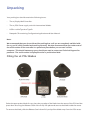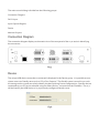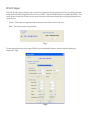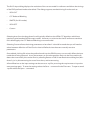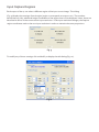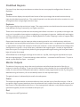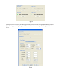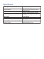
1
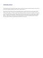
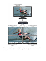
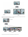
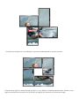
Safety Instructions
To prevent damage to your Datapath product or injury to personnel operating the equipment, please
read the following safety precautions prior to operation. These instructions should be made available to
all those who will use and operate Datapath products.
Power Supply
All Datapath products require a mains power supply. This power supply must be disconnected when
equipment is being upgraded or relocated.
Cables
Do not expose cables to any liquids; doing so may cause a short circuit which could damage the
equipment. Do not place heavy objects on top of any cables as this can cause damage and possibly lead
to exposed live wires.
Ventilation
All computer equipment should be located in a well ventilated area. All ventilation holes on the computer casing must be kept clear of any obstruction at all times. Failure to do so will result in the system over
heating and damaging your equipment.
Working Environment
The equipment should be located in an environment free from dust, moisture and extreme changes
in temperature and should be placed on a stable and solid work surface. Liquids (hot/cold drinks etc)
should not be placed near the equipment as spillage could cause serious damage.
Gas/Flammable Liquids
Electronic equipment should never be used in the presence of gas or any flammable liquid, doing so
could result in an explosion or serious fire.
Smoke/Unusual Smells
Should you notice smoke or unusual smells being emitted from your computer, turn off and unplug the
system from the mains supply. The system should then be passed to a qualified technician for
inspection. Continued operation could result in personal injury and damage to property.
Maintenance
Maintenance should only be carried out by competent technicians, any Datapath plug-in cards that are
physically damaged should be returned to Datapath for repair using Datapath RMA procedures.
Disposal
At the end of life all Datapath products should be disposed of as per local laws and regulations dictate.
In UK contact Datapath to arrange disposal. Our WEE registration number is WEEE/AA0005ZR.
Introduction
The Datapath x4 is a stand alone display wall controller that accepts a standard single or dual-link DVI
input and can flexibly display this across four output monitors.
Each output can be driven as DVI or analog RGB, and can represent an arbitrary crop region of the
original input image. The output resolution and frame rate does not need to be related to that of the
input as the Datapath x4 will optionally upscale and frame-rate convert each cropped region independently. However, if the Datapath x4 detects that frame rates identically match it will automatically
genlock. Additionally, each output can be independently mirrored or rotated through 90°, 180° or
270° to support creative mixes of landscape and portrait monitors.
Configuration Examples
Listed on the next few pages are just a few examples of what can be achieved with the Datapath x4. The
list of examples is not definative and users are encouraged to experiment with different display
orientations
Duplicate the input signal x 4 and displays each duplicate on separate screens
Divide the input signal into quadrants and display each quarter on separate displays with optional frame
rate conversion (in this case 30Hz to 60Hz). Crop regions can be adjusted to provide monitor bezel
compensation.
Duplicate the input signal x2 and display 1 on a single landscape display and divide the 2nd into thirds,
rotate to portrait, upscale and split between 3 displays.
Crop input signal, upscale specific areas and display on 4 separate screens.
Crop the input signal into x4 and display x2 quarters landscape and x2 quarters portrait.
Crop the input signal x4 rotate through 90º,180º or 270º, display in landscape and portrait. Arbitrary crop
regions can allow the monitors to be artistically arranged, but maintain an undistorted image.
Unpacking
Your packing box should contain the following items:
•
The x4 Display Wall Controller.
•
The x4-PSU Power supply unit with international blades.
•
USB 2.0 cable Type A to Type B.
•
Datapath CD containing Configuration Application and User Manual.
Note:
We recommend that you do not discard the packing box until you are completely satisfied with
the x4, and it is fully installed and working correctly. We also recommend that you make note of
the serial number of the controller in a prominent place before you connect it to the
computer. This should hasten any query should you need to contact our Technical Support Department. The serial number is displayed on the x4 and the box label.
Fitting the x4 PSU Blades
Select the appropriate blade for use, place the top edge of the blade into the recess of the PSU and the
press down ensuring the Release Catch clicks firmly into place and secures the blade inside the recess.
To remove the blade, slide the Release Catch down fully and pull the blade away from the PSU recess.
Description
Front panel
Fig.1
Operation Indicators
The front panel has three LED’s to indicate the operational status of the x4:
•
Power
•
Input
•
Status
Power
•
When illuminated, the Power LED indicates the x4 is connected to a mains supply using the
supplied PSU.
Input
•
When illuminated, the Input LED indicates a valid DVI source is connected.
Status
•
Continuous illumination – Indicates the x4 is operating normally.
•
Flashing – Unit is operating over the normal operating temperature. Ensure the input fan vent is not
blocked.
•
If the Status LED goes off and remains off this indicates that the settings configured in the x4
application no longer match the input, this is normally the result of a change of input. The x4 will
compensate for the settings and reconfigure itself to display as near to the settings as possible. The
output will still be displayed but not necessarily as expected.
When the x4 device is connected to a PC by a USB cable, and the x4 Control application is active, then all
three lights flash in turn to help to identify which unit is being controlled.
Rear Panel
Fig.2
Sync Sockets
The Sync sockets are provided for future genlock enhancements. They should be left unconnected.
USB Socket
The USB socket is used to connect the x4 to a PC via a USB connection using the supplied USB Type A to
Type B cable. Configuration of the x4 is programmable via an application utility allowing easy control of
cropping, scaling, rotation and gaps.
DVI-D Input Socket
The DVI-D Input socket is used to connect the DVI input source to the x4. The x4 supports Dual Link DVI,
Single Link DVI and also HDMI (not HDCP compliant) by using the optional DVI/HDMI Adapter.
DVI-I Output Sockets
The four DVI-I Out sockets are used to connect the x4 to the output monitors. The x4 supports both DVI
and analog RGB monitors.
Power
The Power socket is where the power source is connected to the x4. The x4-PSU supplied is plugged into
the Power socket. The power LED on the front of the x4 illuminates when a power supply is
connected.
Setting up the x4
•
Ensure the power supply for the DVI source is disconnected.
•
Connect the cable from the DVI source to the input socket on the rear of the x4.
•
Connect the four displays to the output sockets on the rear panel of the x4.
•
Connect the x4-PSU to the x4 and switch on the power supply at the mains socket using the correct
international blade (see page 9). •
Power up the DVI source.
The Power LED located on the front panel will illuminate to indicate that power has successfully been
applied to the unit. The x4 incorporates an internal processor that will continuously monitor the received DVI signal, and
whenever a valid and stable input is detected the Input LED is illuminated.
If the Input LED is not illuminated, the x4 cannot detect a valid DVI input source.
During operation, the x4 is able to adjust its internal operation to maintain the programmed output proportions even when the input resolution changes.
Fig.3
Configuring the x4
Factory Default Settings
The x4 stores a number of parameters to configure its operation. This allows it to operate stand alone
in a very flexible manner. The configurations affect the input and output display modes as well as the
required partitioning of the input image between monitors.
By default the x4 is configured as follows:
Input EDID Preferred Mode: 1920 x 1080 x 60Hz (SMPTE timings)
Output monitor mode:
Use Monitor Preferred Mode
Default : 1920 x 1080 x 60Hz (SMPTE)
Cropping Mode: 2x2 equal split (960x540)
No Rotation
The default settings are changed using the Windows® application provided, which can be run on any
Windows® platform and connected to the x4 via the supplied USB cable. A description of the use of
the application is provided in the x4 Control Application section.
The sections below describe the settings that are possible and why they may be needed. For details
on how to program the x4 hardware with your desired configurations, please see the x4 Control
Application section.
Configuring DVI Input resolution
Because the timings and resolution of the DVI input are set by the DVI source machine, the x4 can only
configure this indirectly by presenting a programmable “Preferred Mode” as part of its EDID
(Extended Display Identification Data).
Most graphics cards and HDMI appliances automatically select the “Preferred Mode” resolution and
timings presented by the x4 EDID, but they may need to be forced to re-detect if the EDID contents
are changed by the x4 application. This would typically be via a hot-plug event caused by
disconnecting and reconnecting the DVI input cable.
The configuration application will allow readback of the resolution that is currently being detected, as
well as the ability to read and write the internal EDID rom.
Monitor Outputs
The x4 can be configured to read the corresponding EDID of each monitor that is connected and to
drive out a signal that corresponds to the resolution, timings and mode (RGB or DVI) of the Preferred
Mode. This is the factory default configuration.
Please note that when different monitors are attached to the four outputs, each may advertise a
different Preferred Mode, therefore each output will be driven at a different mode.
Whenever the monitor EDID is used, the x4 will calculate the internal scale factors to ensure that the
monitor (at whatever resolution it is being driven) will still display the correct proportion of the input image.
If an EDID cannot be read (for example if the monitor cable does not support the DDC signals required),
there is a default mode that can be programmed into the x4’s memory. This is factory configured to
1080p.
In some cases it may be that the user requires a very specific output timing (for example when
genlocking to the input) irrespective of the monitor EDIDs. In this case the x4 can be configured to always output the mode that has been programmed as the default mode.
Selecting the Regions to Be Displayed
Each output of the x4 can take its display data from any arbitrary rectangular region of the captured
input image. The factory default for these cropping rectangles configures the four monitors to display a
quarter of the input as a 2x2 array, and these proportions are maintained across different input
resolutions.
For a 1080p input, this means that 960x540 pixels from the input image would be upscaled by a factor of
2 in each direction if the selected output resolution was 1080p.
However if the input resolution were to change to 1600x1200, then for the same output monitor the x4
would upscale from an 800x600 region and would reprogram its scale factors to 2.4 horizontally and 1.8
vertically to support the same 1080p monitor.
The cropping regions can be assigned aribitrarily and can overlap, the only restriction being that the
resulting scale factor must be greater than 1.0 (ie 1:1 or upscaled) in either direction. As an example it is
possible to use the x4 to output four identical copies of the input signal (providing the resulting output
timings remain within the capabilities of the single-link DVI outputs).
The regions of the input image to be displayed on a given output monitor can be programmed via USB
by using the Datapath configuration application.
In order to support portrait orientation of monitors, the source data can be rotated by 90º, 180º or 270º
as it is output to the monitor.
Operating Instructions
DVI Input
When the X4 is powered up successfully and the Power, Input and Status LED indicators are
illuminated, this indicates that a DVI input mode has been detected and is working normally.
If the Input LED indicator is not on, check to ensure a single or dual link DVI cable is correctly fitted to
the appropriate sockets.
Once the LED indicators are illuminated, the X4 will display the source across all four screens according
to the configuration that is stored in its non-volatile memory. The x4 is factory configured to display the
input image as a 2x2 split as shown in Fig.3.
Output
To connect to an analog output, a DVI-I-VGA cables are required. To connect to a DVI output, a DVI-D
cable is required.
At high resolution, DVI signals cannot normally be guaranteed beyond 5m cables due to the nature of
the signal losses inherent in the DVI cables and connectors. Datapath have added active equalization
hardware on the x4 which is able to compensate for these losses and support cable lengths of up to 20m
even at full dual-link resolutions (330Mhz pixel clocks). Lower resolutions will allow even longer cable
lengths.
This allows more flexible positioning of the x4 relative to the source and the displays.
Configuring the x4
The x4 has a USB port to allow a host PC to connect to the x4 box and for the user to program its
configuration. Once configured the x4 will run stand-alone without the need for the USB connection and
will auto detect input resolutions and adjust internal scaling to drive the output monitors
consistently.
Genlock
The Firmware running on the x4 will detect when input and/or output timings are set to identical frame
rates and will automatically genlock the syncs in these cases. In all genlock modes, the timings are
configured to share a common reference clock, so there will be no drift in synchronisation, and
x4 Control Application
Application Installation
Note: Do not plug the x4 into a USB port until the driver installation is complete.
Locate the Install folder on the Datapath CD supplied with the x4, run install.exe. and follow the
installation wizard. During installation a warning message is displayed stating that the driver does not
have Windows® Logo accreditation.
Select Continue Anyway to complete the installation.
The Datapath x4 can now be connected to a suitable USB 1.0 or 2.0 port using the cable supplied. At
this point the hardware will be detected by Windows® as an x4 splitter, and a New Hardware wizard is
displayed. Allow the wizard to search, and click on the recommended option to enable the previously
installed driver to be associated with the new hardware.
Press Continue Anyway to accept the driver.
Running the x4 Control Application
To open the x4 Control application select Start/All Programs/x4 Control.
The application will search for an x4 connected to your computer and display the status of the first x4
detected. Should there be more than one x4 in use, a list of all available x4’s can be found in the File
menu.
Once the application has detected an x4 the main status screen is displayed Fig.4.
Fig.4
The main control dialog is divided into the following groups:
Connection Diagram
DVI-D Input
Input Capture Regions
Device
Monitor Outputs
Connection Diagram
The connection diagram displays a schematic view of the rear panel of the x4 to assist in identifying
the connectors.
Fig.5
Device
The unique USB device name that is connected is displayed in the Device group. It is possible to associate a more user friendly name such as “First Four Outputs”. The friendly name is stored in non-volatile storage on the x4 and can to help identify the device during future configurations. Specific devices
connected to your PC can be selected using the Select Device.. command on the File Menu. The x4’s
will be listed by the USB Device or by a previously configured friendly name.
Fig.6
DVI-D Input
The DVI-D Input group displays the current DVI mode that is being captured (if any) and the prefered
mode that has been programmed into the x4’s EDID. Use the Modify button to update the EDID. The
small square to the left of the current input resolution indicates whether the x4 has genlocked to the
input source.
•
Green – The outputs are genlocked to the input dot clock and vertical sync
•
Red – The outputs are not genlocked
Fig.7
To change the timings of the input EDID click on the Modify button and the following dialog is
displayed. Fig 8.
Fig.8
The DVI-D Input dialog displays the resolution of the current mode for reference and allows the timings
of the EDID prefered mode to be edited. The dialog supports standard timing formulae such as:
•
VESA CVT
•
CVT Reduced Blanking
•
SMPTE (for HD modes)
•
VESA GTF
•
Custom
Selecting Auto from the drop down list will typically default to the VESA CVT algorithm which best
matches typical standard VESA output modes. However, to minimise dot clocks and hence maximise
DVI cable lengths, the CVT Reduced Blanking is recommended.
Selecting Custom allows the timing parameters to be edited. It should be noted that you will need to
select between definition of Pixel Clock or Vertical Refresh since these are mutually excusive
parameters.
Once edited, clicking OK writes the prefered mode into the EDID but may not normally affect the input
mode that is being captured. It may be necessary to force the graphics device in the host machine to
detect the new modes, this can be done by selecting Detect on the Screen Resolutions dialog box (Windows® 7) or by disconnecting the souce from the x4 and reconnecting.
All modifications to the input settings can be save as a .vqs file, removing the requirement to input the
same settings again. To save the settings select the Save… command in the File menu. To open a saved
.vqs file select the Open… command.
Input Capture Regions
Each output of the x4 can select a different region of the input source image. This dialog
(Fig. 9) displays the settings of each region (region 1 corresponds to output 1 etc). The numbers
denote the top, left, width and height coordinates of the region that is to be displayed. Note, these are
described in terms of the current active input resolution. If the input resolution changes, the capture
region coordinates scale to the new input resolution in order to maintain the same proportions.
Fig. 9
To modify any of these settings click on Modify to display the edit dialog (Fig. 10).
Fig.10
Predifined Regions
For ease of use, there are preset buttons to select the two most popular configurations: Quarter or
Replicate.
Quarter
The first monitor displays the top left hand corner of the input image, the second monitor the top
right, the third the bottom left etc. This mode of operation can be used to drive four monitors in a 2x2
arrangement from a single high resolution input.
Replicate
Each output displays the entire input image. The output monitors can be driven at the same resolution
(with different timings if necessary) or a higher resolution.
There are no restrictions (other than the resulting scale factor must be 1:1 or upscale) in the region settings, so it is possible to have regions overlapping, or to program in gaps etc. Additionally each region
can have a transform such as rotation or flipping applied to it (after cropping) in order to support different output monitor orientations.
Please note that there may be instances where a setting stored in non-volatile memory which was
valid when it was stored (ie the scale factors from input to output were 1:1 or greater) may subsequently require down-scaling if the resolution of the input increases. In this case the firmware will adjust the
scaling factors to give a 1:1 crop of the input, centred on the original region. In order to signal that at
least one output is no longer exactly honouring the programmed region setting, the front panel status
light will not be illuminated.
All modifications to the Region settings can be save as a .vqs file, removing the requirement to input
the same settings again. To save the settings select the Save… command in the File menu. To open a
saved .vqs file select the Open… command.
Monitor Outputs
The Monitor Outputs group shows the actual resolution and refresh rate that each of the four x4
outputs is currently providing. To see more information such as whether this is an analog RGB or DVI
mode, if it is the monitor EDID preferred mode or a default mode programmed into the x4, along with
detailed timing information, click on the Modify button for the required output.
The genlock status is indicated by the small coloured squares:
Green
The outputs are genlocked to a common reference clock, and the Vsync of the first monitor. If the Input genlock light is green (see above), then the reference clock is taken from the input DVI source, and
the system is fully genlocked to this source. If the input genlock indicator is red, then the outputs are
genlocked together, but are not related to the input sync.
Red
The outputs are NOT genlocked
Fig.11
Individual monitor outputs can be configured by clicking on the corresponding Modify button.
This will bring up a timing dialog similar to that of the input timings. This dialog is shown in
Fig.12.
Fig.12
The source of mode selection controls whether the x4 output should take its timing values and
resolution from the preferred mode of the monitor that is connected, or use its internally programmed
‘default’ mode. Please note that only the internal default timings can be edited in this dialog.
If Use the Monitors Preferred Mode is selected, but no valid EDID can be read from the attached
monitor, then the x4 firmware will program the output to use the default mode timings.
The rest of the dialog is identical to that for setting the Input timings, with the exception that for the
output monitors it is possible to select Analog RGB (“VGA”) output as well as DVI.
All modifications to the Output… settings can be save as a .vqs file, removing the requirement to input
the same settings again. To save the settings select the Save… command in the File menu. To open a
saved .vqs file select the Open… command.
Finally there is a Test button which should be used when defining a default mode that you are not sure
the attached monitor can support. In test mode, the output timings are programmed, but they are not
saved to non-volatile memory on the x4 until the OK button is pressed to accept the mode.
Specification
x4 Physical Dimensions
235 x 175 x 44mm/9.25” x 6.9” x 1.75”
Operating Temperature Range
Power Requirements
0 - 35 DegC/32 - 96 DegF
5V DC, 11W. Universal mains power adapter
supplied (100-240V)
The unit contains a cooling fan. The input
and output vents should not be restricted
Full speed (12Mbits/s) operation supported
To 330 Mpixels/s
4k x 4k maximum
To 165Mpixels/s
Up to 2.5Mpixel (maximum 2048 pixels in
either direction)
64 x original surface area
Updates supported via USB
Cooling
USB 2.0
1 x Dual link DVI capture
Input Surface
4 x Single link DVI or analog RGB outputs
Output Screens Resolutions
Arbitary Up Scaling
Firmware Support
Datapath Limited
Datapath has a long and very successful history in the computer graphics industry. Datapath has been
designing and supplying high performance, high quality graphics display systems to the world’s largest and most demanding companies and institutions since 1982. Datapath was one of the founding
companies of multi-screen Windows acceleration using single and multi board solutions. Now using
the very latest display technology Datapath offers some of the world’s leading multi screen graphics
accelerators for the most demanding applications.
As new technology advances, so we at Datapath improve the performance and functionality of both
our hardware and software to give our customers more. Following a continuous development program, we pride ourselves on our support and responsive nature towards all our customers and their
changing needs. As more sophisticated equipment and techniques become readily available, so we
are there to exploit the power and potential that this technology presents.
Technical Support
Registered Users can access our technical support line using, email, and the Support page on the Datapath Web Site, usually with a response within 24 hours (excluding weekends).
Via Email
Send an email to [email protected] with as much information about your system as possible.
To enable a swift response we need to know the following details:
•
Specification of the PC - including processor speed
•
Operating System
•
Application Software
•
Datapath Hardware / Software
•
The exact nature of the problem - and please be as specific as possible.
Please quote version and revision numbers of hardware and software in use wherever possible.
Copyright Statement
© Datapath Ltd., England, 2011
Datapath Limited claims copyright on this documentation. No part of this documentation may be
reproduced, released, disclosed, stored in any electronic format, or used in whole or in part for any
purpose other than stated herein without the express permission of Datapath Limited.
Whilst every effort is made to ensure that the information contained in this User Manual is correct,
Datapath Limited make no representations or warranties with respect to the contents thereof, and
do not accept liability for any errors or omissions. Datapath reserves the right to change specification
without prior notice and cannot assume responsibility for the use made of the information supplied.
All registered trademarks used within this documentation are acknowledged by Datapath Limited
UK Headquarters and Main Sales Office
Datapath Ltd.,
Alfreton Road,
Derby, DE21 4AD, UK
Tel: +44 (0) 1332 294441
Fax: +44 (0) 1332 290667
Email: [email protected]
www.datapath.co.uk
Index
A
Application Installation 16
C
configuration 13
Configuring the x4 15
Cooling 24
Copyright Statement 25
Crop regions 6
D
Default Settings 13
device name 17
display orientations 5
DVI-D Input 18
I
Input socket 11
Input Surface 24
L
LED’s 10
M
mirrored 4
Modify button 22
Monitor Outputs 21
O
Out sockets 11
P
Power socket 11
PSU Blades 9
PSU Power supply 9
Q
Quarter 21
R
regions to be displayed 14
Replicate 21
rotate to portrait 7
S
safety precautions 3
T
Technical Support 25
U
UK Headquarters 26
Up Scaling 24
USB socket 11