1
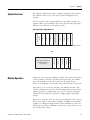
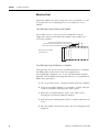
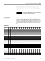
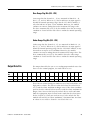
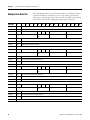
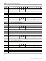
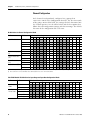
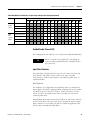
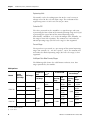
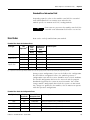
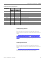
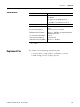
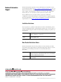
Module Data, Status, and Channel Configuration
Chapter 3
1769-IF16V Module: Bit Definitions for Input Range and Input Data Configuration Words
Define
To Choose
Make these bit settings
15
Input
Range
Select
Input
Data
Format
Select
14
13
12
11
10
09
08
03
02
01
00
-10…+10V
0
0
0
0
0…5V
0
0
0
1
0…10V
0
0
1
0
1…5V
0
0
1
1
Proportional Counts
0
0
0
Engineering Units
0
0
1
Scaled for PID
0
1
0
Percent Range
0
1
1
07
06
05
04
Enable/Disable Channel (EC)
This configuration selection lets each channel be enabled individually.
TIP
When a channel is not enabled (0), no voltage or
current reading is provided to the controller by the
A/D converter.
Input Filter Selection
The input filter selection field lets you select the filter frequency for
each channel. The filter frequency affects the noise rejection
characteristics, channel step response, and module update time, as
explained below.
Noise Rejection
The modules use a digital filter that provides noise rejection for the
input signals. The filter is programmable, allowing you to select from
five filter frequencies for each channel. A lower frequency (60 Hz
versus 315 Hz) can provide better noise rejection but it increases
channel update time.
Normal Mode Rejection is better than 50 dB at 50 and 60 Hz, with the
50 and 60 Hz filters selected, respectively. Transducer power supply
noise, transducer circuit noise, or process variable irregularities may
also be sources of normal mode noise.
Publication 1769-UM018A-EN-P - October 2008
39