1
Order this document
by AN2010/D
Motorola Semiconductor Application Note
AN2010
Using The Motorola msCAN Filter Configuration Tool
by
Steven McAslan
Body Electronics Software Systems
East Kilbride, Scotland.
1 Introduction
The Controller Area Network (CAN) communication standard is widely
used in automotive and industrial applications to signal between nodes
on a network. One of the reasons for its success in such areas is the
availability of CAN modules integrated onto microcontrollers intended for
embedded applications. The Motorola msCAN is one such module that
is available on both the 8-bit M68HC08 family of devices and the 16-bit
M68HC12 family. As well as providing a robust implementation of the
CAN standard, the msCAN is able to reduce the overhead on the
microcontroller CPU by filtering out unwanted CAN messages before
they reach its input buffers. This application note describes the use of a
software tool that provides automated configuration for the msCAN filter
based on the messages that are present on the CAN network. Used in
conjunction with the Filter Generator’s user’s manual it provides practical
examples and tips on how to best use the tool.
2 The benefits of filters
The CAN standard allows for a very large number of nodes on a single
network. However, each individual node will typically only require to
receive and transmit a subset of the messages on the network. If the
msCAN were to receive every message present on the network then the
microcontroller CPU would spend time analysing messages only to
discover that many were not of interest to that particular node. In
networks where the node was interested only in a small subset of the
© Motorola, Inc., 2000
AN2010
Application Note
total messages available then a significant amount of processing time
could be lost performing worthless evaluations. To allow the processor
to avoid doing this, Motorola provides filters on the msCAN module that
will prevent certain unwanted messages from reaching the input buffers
and thus requiring the CPU’s attention.
The user must configure these filters to best suit the message traffic on
the network to which the node belongs. Although this is not a trivial task,
it is performed at design time and the extra effort spent in the design
phase will translate to improved runtime CPU utilisation.
3 How filters work
In the simplest case, filters work by applying a logical comparison to
individual bits in the CAN message identifier. For each filtered bit, the
comparison can be either
Test if bit is logic ‘1’
or
Test if bit is logic ‘0’
or
Ignore value of bit
Consider the following example. Suppose that the filter examines the
eleven bits of a standard CAN message identifier. For each bit, the filter
will check if the Id contains a logic ‘1’ (represented by ‘1’), a logic ‘0’
(represented by ‘0’), or either logic ‘1’ or logic ‘0’ (represented by ‘x’). In
this simple example there are only three possible CAN messages. The
filter will accept two of the messages and reject one.
Filter value:
0001x1001x0
Message 1:
00011100110
Message 2:
00110100110
Message 3:
00010100100
In this case the filter will reject Message 2 since its third most significant
bit is not ‘0’ – 001... rather than 000….
In effect the filter is simply a convenient way of defining the set of
messages that the CPU must receive. In the above example there are
two bits whose value is ignored and 9 whose value is fixed. This gives a
set of four identifiers that the filter will pass – 00010100110,
00010110110, 00011100110, 00011110110.
AN2010
2
MOTOROLA
The msCAN filters
4 The msCAN filters
The msCAN provides the features described above and adds further
flexibility by allowing the user to configure the filter in a number of ways.
For the M68HC08 family the filter may act as a single 32-bit value that
operates across the full 29-bits of an extended CAN message identifier.
In this case the filter identifies two sets of messages: one set that it
receives and one set that it rejects. Alternatively, the filter may be split
into two. This allows the msCAN to examine only the first 16 bits of a
message identifier, but allows two separate filters to perform the
checking. In our simple example, this would allow Message 2 to be
accepted by the extra filter now available:
Filter value A:
0001x1001x0
Filter value B:
00x101x01x0
Message 1:
00011100110
Message 2:
00110100110
Message 3:
00010100100
Now the msCAN will accept all three messages. Filter A will accept
Messages 1 and 3 as before and filter B will accept Message 2.
For the configuration that uses two filters, there are four sets of
messages: accepted by Filter A, rejected by Filter A, accepted by Filter
B, rejected by Filter B. In practice, it is unimportant which filter accepts
the message – messages accepted by either will be placed in the input
buffer. This means that a message may be accepted by more than one
filter. In our example both Filter A and Filter B accept Message 3.
The filter may be further split into four 8-bit filters that examine only the
first 8 bits of a message identifier. In this case the filter can accept or
reject complex sets of message identifiers - only however, where the
variation is in the first eight bits of the identifier. For the M68HC08 family
the possible filter combinations are:
1 x 32-bit filters
2 x 16-bit filters
1 x 16-bit filter, 2 x 8-bit filters
4 x 8-bit filters
In the case of the M68HC12 msCAN module there is a second 32-bit
filter that can be configured in the same way as the first filter. In other
AN2010
MOTOROLA
3
Application Note
words, for the M68HC12 family the msCAN has the following
combinations:
2 x 32-bit filters
1 x 32-bit filter, 2 x 16-bit filters
1 x 32-bit filter, 4 x 8-bit filters
2 x 16-bit filter, 4 x 8-bit filters
4 x 16-bit filters
8 x 8-bit filters
In practice the msCAN filter uses three sets of registers to provide the
filter configuration. Firstly, the CIDAC register determines the
configuration of the banks into filter sizes and number of filters.
Secondly, registers CIDMR0/1/2/3 determine those bits on which the
filter will operate by placing a ‘0’ at the appropriate bit position in the filter
register. Finally, registers CIDAR0/1/2/3 determine the value of those
bits determined by CIDMR0/1/2/3.
For instance in the case of our simple example with the filter value of:
0001x1001x0
The CIDMR0/1/2/3 register would be configured as:
00001000010
and so all message identifier bits except bit 1 and bit 6 would be
compared against the CIDAR0/1/2/3 registers. These would be
configured as:
00010100100
In this case bits 1 and 6 are set to ‘0’, but since they are ignored it is
equally valid to set them to ‘1’.
AN2010
4
MOTOROLA
The Configuration Problem
5 The Configuration Problem
This powerful flexibility brings with it a problem of its own. Namely, how
to select the best configuration of filter size/number AND filter values to
most efficiently reject those messages that the node wishes to ignore.
Note that for any configuration, it is essential that a required message is
never rejected, and in many cases this may mean that the filter has to
accept messages that are not used by the node. In this situation, the
microcontroller CPU must still perform acceptance testing on each
message accepted by the filter, although it would have to examine fewer
messages than would be the case without a filter. Even in systems with
only moderate complexity, this filter configuration may be extremely
complex and time consuming for a node programmer to select. In
addition, it may not be apparent (without much further work) to confirm
whether a selected combination is the most efficient at reducing CPU
overhead in message acceptance.
For the above reasons Motorola has developed an msCAN Filter
Generator software tool. The objective of the tool is to automate the
selection of filter values for the msCAN module. The tool can search
through many combinations of filter values, select the most efficient that
it can detect, and provide the values to the user in a form that can be
readily used.
The rest of this application note provides examples to illustrate typical
uses of the tool. Note that some less significant details of using this tool
are not discussed here but are fully described in the software user’s
manual.
AN2010
MOTOROLA
5
Application Note
6 Using the Filter Generator
The user can configure the filter generator software to operate in a
variety of different modes, however, Software Example 1 begins by
examining the basic operation.
The filter generator software creates the filter configuration by examining
message identifiers contained in two lists. The first list contains all of the
message identifiers that the node wishes to accept; the second list
contains all of the message identifiers used in the network. The software
will examine the accepted message list and propose a filter configuration
that will accept all of these messages. Next the software will compare
the network list against the filter and determine which messages will be
accepted and which will be rejected. Finally, the software will produce a
listing of its results either to the screen or to a text file. Particularly in the
case where there are a large number of messages, it may not be
possible to select the best filter configuration on the first pass. For this
reason, the software can automatically repeat the process up to 10,000
times and select the best configuration that it detected.
For many cases this simple mode will be sufficient to produce an
effective filter configuration, so before examining further options for the
software, consider the preparation of the message lists for use by the
filter generator. The software always reads the message lists from two
text files. The exact format of these files, again, is configurable, but in the
simplest case they consist of lists of hexadecimal numbers. Consider the
following example:
AN2010
6
MOTOROLA
Software Example 1
7 Software Example 1
In this case the message list files are contained in a folder named
“messages” on the C: drive. The wanted message list is “wanted.txt” and
the network list is “network.txt”. Each file contains standard CAN (11 bit)
message identifiers. The content of each file is shown below:
File c:\messages\wanted.txt
0x245
0x256
0x392
0x376
File c:\messages\network.txt (This must contain all the messages
in wanted.txt too)
0x067
0x068
0x069
0x123
0x245
0x256
0x257
0x376
0x392
0x393
Execute the filter generator software by typing the following command in
a DOS window (on a single line):
mscanfg -nf 1 -w c:\messages\wanted.txt -m
c:\messages\network.txt -iw 1 -im 1 -t 100 -d
The filter generator will configure a single 32-bit filter to best match the
data 100 times and then produce a detailed output description in the
DOS window. Note that some warning messages will also be created
when using the above operating mode – these can be ignored at this
stage. The filter generator will display the calculated filter values in the
DOS window.
For this example the filter generator produces the following output:
AN2010
MOTOROLA
7
Application Note
It took 100 loops to find the optimal filter
### MSCAN Filter List, generated by the MSCAN Filter Generator
###
Number of filters: 2
Filter size:
16
Number of wanted messages: 4
Number of unwanted messages: 6
Number of unwanted but accepted messages:
Rejection ratio:
83
# Filter values:
Filter 0: value 0x4ae0
mask 0x0260
Filter 1: value 0x7ec0
mask 0x1c80
1
(0100101011100000)
(0000001001100000)
(0111111011000000)
(0001110010000000)
# List of unwanted messages that will be accepted by the current
filter pattern:
Message CAN ID:
0x257
Accepted by filter:
1
# List of wanted messages accepted by different filters
Message CAN ID: Accepted by filter:
0x392
0
0x245
2
0x256
1
0x376
3
NOTE:
You MUST place a space between the option switch and its value e.g.
-im 1 NOT -im1. You can increase the number of iterations by changing
the –t 100 parameter.
AN2010
8
MOTOROLA
Software Example 2
8 Software Example 2
The information for a network may not be stored in a convenient textual
format as shown above. In particular, the wanted and the network
messages may be stored in a single list in some other “standard”
application. This example explains how to extract the information
required from these lists and configure the Filter Generator to read the
new lists correctly.
Suppose the information is stored in Microsoft Word format as a table:
Message Name
Message Id
Source node
Receiving nodes
Temperature1
1553458A
Sensor1
Dashboard, HVAC
Temperature1
1553558A
Sensor2
Dashboard
Temperature1
1555658A
Sensor3
HVAC
DriverTemp
12694002
ControlPanel
HVAC
PassengerTemp
12694003
ControlPanel
HVAC
WindowPosition
17334467
Door1
HVAC
DoorOpen
17334465
Door1
Dashboard
WindowPosition
17334477
Door2
HVAC
DoorOpen
17334475
Door2
Dashboard
The table contains all of the information for messages in a very simple
network. This example examines the configuration of the filter generator
for the HVAC node. The CAN message Ids are in extended format and
these require an additional piece of information to be read correctly.
There are 9 steps to follow:
1. Copy the table to another document
2. Insert an additional column in the table (after the Id column) to
indicate extended Ids used, place ‘1’ in each row.
3. Delete the header row (or comment it by placing a ‘/’ character in
front of it)
4. Add the hexadecimal delimiter in front of each Message Id.
5. Convert the table to text format separated by commas ‘,’.
AN2010
MOTOROLA
9
Application Note
6. Save the file in text format as “network2.txt”
Temperature1, 0x1553458A, 1, Sensor1, Dashboard, HVAC
Temperature1, 0x1553558A, 1, Sensor2, Dashboard
Temperature1, 0x1555658A, 1, Sensor3, HVAC
DriverTemp, 0x12694002, 1, ControlPanel, HVAC
PassengerTemp, 0x12694003, 1, ControlPanel, HVAC
WindowPosition, 0x17334467, 1, Door1, HVAC
DoorOpen, 0x7334465, 1, Door1, Dashboard
WindowPosition, 0x17334477, 1, Door2, HVAC
DoorOpen, 0x17334475, 1, Door2, Dashboard
7. Delete lines in the table that do not have the HVAC as a receiver
8. Save the file in text format as “wanted2.txt”
Temperature1, 0x1553458A, 1, Sensor1, Dashboard, HVAC
Temperature1, 0x1555658A, 1, Sensor3, HVAC
DriverTemp, 0x12694002, 1, ControlPanel, HVAC
PassengerTemp, 0x12694003, 1, ControlPanel, HVAC
WindowPosition, 0x17334467, 1, Door1, HVAC
WindowPosition, 0x17334477, 1, Door2, HVAC
9. Run the filter generator using the following command:
mscanfg -nf 2 -w c:\messages\wanted2.txt -m
c:\messages\network2.txt -iw 2 -im 2 -t 1000 -d -p ”,” -e
For this example the filter generator produces the following output:
It took 1000 loops to find the optimal filter
### MSCAN Filter List, generated by the MSCAN Filter Generator
###
Number of filters: 2
Filter size:
32
Number of wanted messages: 6
Number of unwanted messages: 3
Number of unwanted but accepted messages:
Rejection ratio:
100
0
# Filter values:
Filter 0: value
mask
Filter 1: value
mask
0xbbde88ee
0x2ac408ea
0xaabecb14
0x00244000
(10111011110111101000100011101110)
(00101010110001000000100011101010)
(10101010101111101100101100010100)
(00000000001001000100000000000000)
# List of unwanted messages that will be accepted by the current
filter pattern:
Message CAN ID:
Accepted by filter:
AN2010
10
MOTOROLA
Software Example 3
# List of wanted messages accepted by different filters
Message CAN ID:
0x17334467
0x17334477
0x12694003
0x1555658a
NOTE:
Accepted by filter:
0
0
2
1
The -e option tells the Filter Generator that the file contains message Ids
that are in extended format. To tell the Filter Generator which Ids are in
extended format the data field immediately following the Id must be a ‘1’.
If the data is a standard Id the data field must contain ‘0’. Extended and
standard messages Ids can both be used in the same file.
If the information is stored in Microsoft Excel format then follow the
above sequence except that steps 5 and 6 can be executed as a single
step using the save as comma delimited text (CSV).
9 Software Example 3
In the examples so far the filter configuration has been left to the Filter
Generator tool. In these cases the tool itself will decide on the optimum
configuration of filter size. However, the user can define the exact filter
configuration to use by specifying the number of filters and their size.
This may be a useful feature to take advantage of where there is a visible
pattern obvious to the user or perhaps where a minor change is made to
the network and the filter configuration should remain as before.
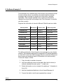
The -nf and -s options are used to define the configurations. From the
earlier description of the filter options on the 68HC08 and 68HC12
families the possibilities available to configure the tool are:
Family
Option
Configuration
68HC08
-nf4 -s8
4 x 8 bit filters
68HC08
-nf2 -s16
2 x 16 bit filters
68HC08
-nf1 -s32
1 x 32 bit filters
68HC12
-nf8 -s8
8 x 8 bit filters
68HC12
-nf4 -s16
4 x 16 bit filters
68HC12
-nf2 -s32
2 x 32 bit filters
AN2010
MOTOROLA
11
Application Note
To demonstrate the effect of forcing filters to certain sizes, Software
Example 2 can be re-run with the filter size forced to 16:
mscanfg -nf 4 –s 16 -w c:\messages\wanted2.txt -m
c:\messages\network2.txt -iw 2 -im 2 -t 1000 -d -p ”,” –e
This produces a result that is not so efficient:
It took 1000 loops to find the optimal filter
### MSCAN Filter List, generated by the MSCAN Filter Generator
###
Number of filters: 4
Filter size:
16
Number of wanted messages: 6
Number of unwanted messages: 3
Number of unwanted but accepted messages:
Rejection ratio:
33
# Filter values:
Filter 0: value 0xb99e
mask 0x0000
Filter 1: value 0xaaba
mask 0x0000
Filter 2: value 0xaa9e
mask 0x0000
Filter 3: value 0x935a
mask 0x0000
2
(1011100110011110)
(0000000000000000)
(1010101010111010)
(0000000000000000)
(1010101010011110)
(0000000000000000)
(1001001101011010)
(0000000000000000)
# List of unwanted messages that will be accepted by the current
filter pattern:
Message CAN ID:
0x1553558a
0x17334475
Accepted by filter:
2
0
# List of wanted messages accepted by different filters
Message CAN ID:
0x17334467
0x1555658a
0x17334477
0x12694003
0x12694002
0x1553458a
Accepted by filter:
0
1
0
3
3
2
AN2010
12
MOTOROLA
Software Example 4
10 Software Example 4
This example examines more advanced features of the Filter Generator.
In particular it looks at the options for generating a C language
configuration file, using an alternative algorithm, and other minor details.
The filter generator can produce a C language function that will configure
the filter registers of the msCAN module – use the -f option. The C file
produced contains an ANSI C function with the following prototype:
void msCANFiltersInit(void)
The Filter Generator includes an alternative algorithm for selecting a
suitable filter configuration. This second option is faster than the main
choice but may require more iterations to achieve the same result as the
main choice – use the -da option. A typical use may be as a first pass on
a new network configuration to determine the complexity of the filter
selection task.
The CAN message Id includes an RTR bit that indicates a Remote
Transmission Request. Like the Extended CAN Id field this data is
determined for each individual Message Id and is placed as a separate
field after the extended field in the input files. If RTR is present then the
filter will operate on this bit also.
In the examples so far the Filter Generator tool has displayed its results
in the DOS window. This is helpful when examining different options and
making judgements on the use of the tool. However, where the output
will be used to configure an msCAN module a text file is a much more
useful outcome. Use the -o option to specify the name of the output file.
Finally, the Filter Generator can produce a detailed "map" of the
operation of the selected filter configuration for the wanted messages –
use -d option. This allows the user to see which filters are accept most
messages and this in turn may be used to optimise the specification of
Message Ids used within the CAN network. All of our examples shown
here use the –d option.
For the Software Example 2 a C language output file called filter.c can
be specified. In addition, a detailed description of the performance of the
selected configuration can be produced by executing the following
command:
mscanfg –nf 2 –w c:\messages\wanted2.txt –m
c:\messages\network2.txt –iw 2 –im 2 –t
500 –d –p ”,” -e –o c:\messages\filter.c
AN2010
MOTOROLA
13
Application Note
This produces the following output message:
It took 500 loops to find the optimal filter
Filter information written to c:\messages\filter.c
and detailed output and C function:
###
###
MSCAN Filter List, generated by the MSCAN Filter Generator
Number of filters: 2
Filter size:
32
Number of wanted messages: 6
Number of unwanted messages: 3
Number of unwanted but accepted messages:
Rejection ratio:
100
0
# Filter values:
Filter 0: value
mask
Filter 1: value
mask
0xbbde88ee
0x2ac408ea
0xaabecb14
0x00244000
(10111011110111101000100011101110)
(00101010110001000000100011101010)
(10101010101111101100101100010100)
(00000000001001000100000000000000)
# List of unwanted messages that will be accepted by the current
filter pattern:
Message CAN ID:
Accepted by filter:
# List of wanted messages accepted by different filters
Message CAN ID:
0x1553458a
0x12694002
0x17334477
0x17334467
Accepted by filter:
0
2
1
1
# C function to initialize MSCAN filters:
void msCANFiltersInit( void )
{
/* Be sure that SFTRES bit is set! */
CIDAC = 0x0;
(unsigned long *)CIDAR0 = 0xbbde88ee;
(unsigned long *)CIDMR0 = 0x2ac408ea;
(unsigned long *)CIDAR4 = 0xaabecb14;
(unsigned long *)CIDMR4 = 0x00244000;
return;
}
AN2010
14
MOTOROLA
Other Considerations
11 Other Considerations
Although the Filter Generator tool has a wide range of options to
examine message data, it does so in a static sense. In other words, it
takes no account of the number of times each message is broadcast on
the network. This means that although a filter may appear to be highly
successful by accepting only a single message out of many rejected, if
this accepted message is the most common on the network, the CPU
overhead in dealing with it may still be large. In this case it may be more
effective to modify the filter generator configuration options to force this
regular message to be rejected and to accept others that are less often
transmitted.
Due to the hardware implementation of the msCAN filter itself, some
standard Ids may be inadvertently rejected because the filter does a
pattern match on more than the message Id itself. This can occur when
a standard Id is used with a 16-bit filter size. The 11-bit Id itself, the
extended Id indicator (IDE bit) and the RTR bit are all handled as
required, leaving three bits in the 16-bit filter undefined. If these lower 3
mask bits are set to ‘0’ then the filter comparison will continue beyond
the Id section of the message into the next sections of the message that
may be DLC, data etc. To avoid this problem, the least significant three
bits of the 16 bit mask register (CIDMR1/3) must be set to ‘1’ to force the
filter to ignore message bits that are not part of the Id.
12 Conclusion
The Motorola msCAN Filter Generator provides a powerful and flexible
way of optimising the filter configuration on an msCAN module. This in
turn can greatly reduce the CPU overhead for handling CAN messages
not intended for a particular node.
13 Software Availability
To receive further information about the msCAN Filter Generator tool
and to obtain the software itself send an email to
[email protected] with msCAN Filter Generator
in the subject line.
AN2010
MOTOROLA
15
Motorola reserves the right to make changes without further notice to any products herein. Motorola makes no warranty, representation or guarantee regarding the suitability of its
products for any particular purpose, nor does Motorola assume any liability arising out of the application or use of any product or circuit, and specifically disclaims any and all liability,
including without limitation consequential or incidental damages. "Typical" parameters which may be provided in Motorola data sheets and/or specifications can and do vary in different
applications and actual performance may vary over time. All operating parameters, including "Typicals" must be validated for each customer application by customer's technical experts.
Motorola does not convey any license under its patent rights nor the rights of others. Motorola products are not designed, intended, or authorized for use as components in systems
intended for surgical implant into the body, or other applications intended to support or sustain life, or for any other application in which the failure of the Motorola product could create a
situation where personal injury or death may occur. Should Buyer purchase or use Motorola products for any such unintended or unauthorized application, Buyer shall indemnify and hold
Motorola and its officers, employees, subsidiaries, affiliates, and distributors harmless against all claims, costs, damages, and expenses, and reasonable attorney fees arising out of,
directly or indirectly, any claim of personal injury or death associated with such unintended or unauthorized use, even if such claim alleges that Motorola was negligent regarding the
design or manufacture of the part. Motorola and
are registered trademarks of Motorola, Inc. Motorola, Inc. is an Equal Opportunity/Affirmative Action Employer.
How to reach us:
USA/EUROPE: Motorola Literature Distribution; P.O. Box 5405, Denver, Colorado 80217. 1-303-675-2140
Mfax: [email protected] – TOUCHTONE 1- 602-244-6609, http://sps.motorola.com/mfax
US & CANADA ONLY: http://sps.motorola.com/mfax
HOME PAGE: http://motorola.com/sps/
JAPAN: Motorola Japan Ltd.; SPS, Technial Information Center, 3-20-1, Minami-Azabu, Minato-ku, Tokyo 106-8573 Japan.
81-3-3440-3569
ASIA/PACIFIC: Motorola Semiconductors H.K. Ltd.; Silicon Harbour Centre, 2 Dai King Street, Tai Po Industrial Estate,
Tai Po, N.T., Hong Kong. 852-266668334
CUSTOMER FOCUS CENTER: 1-800-521-6274
Mfax is a trademark of Motorola, Inc.
© Motorola, Inc., 2000
AN2010/D