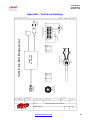
1
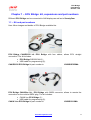
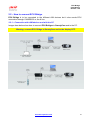
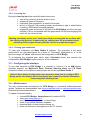
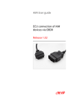
ECU Bridge User Manual ECU Bridge User Manual Release 1.08 Introduction ECU Bridge belongs to the last generation of AIM loggers for car/bike installations. There are two available versions of ECU Bridge: K line/CAN version – with OBDII connector – for an easy and quick Plug&Play connection to the vehicle OBDII plug (suggested for stock ECUs). RS232/CAN version – with free cables – for a straight ECU connection through the serial/CAN communication protocol (suggested for both stock and after market ECUs). Supported ECUs database is constantly updated. Refer to www.aim-sportline.com “Download Area/ECU connections” for further information. ECU Bridge samples but does not record data out coming from the vehicle ECU; it can show them if connected to an high technology AIM display like MyChron3 Dash, TGDash and Formula Steering Wheel or to SmartyCam, the AIM on board camera the only one with data overlay. ECU Bridge manages 3 different communication protocols: K Line; CAN Line; Serial RS232 line. Technical Characteristics: ECU interface; CAN protocol for external expansion modules; USB port for programming 8/18 V external power. www.aim-sportline.com 1 ECU Bridge User Manual Release 1.08 Index Chapter 1 – ECU Bridge: kit, expansions and part numbers ......................................... 3 1.1 – Kit and part numbers ......................................................................................................................... 3 1.2 – ECU Bridge available expansions and related part numbers ........................................................ 4 Chapter 2 – Installation, power and connections ........................................................... 5 2.1 – How to power ECU Bridge ................................................................................................................. 5 2.1.1 – Cable labelled GND ...................................................................................................................... 5 2.2 – How to connect ECU Bridge. ............................................................................................................ 6 2.2.1 – Connection with AIM devices and with the PC ............................................................................. 6 2.2.2 – Connection of CAN/K Line ECU Bridge to the OBDII plug ........................................................... 8 2.2.3 – Connection of RS232/CAN ECU Bridge to the ECU .................................................................... 9 Chapter 3 – Driver, configuration, sampled data visualisation, engaged gear computation and maintenance ....................................................................................... 10 3.1 – Visualising data sampled by ECU Bridge on SmartyCam video ................................................. 11 3.2 – Gear computation procedure .......................................................................................................... 11 3.2.1 – Preliminary Information ............................................................................................................... 12 3.2.2 – Activating the procedure ............................................................................................................. 12 3.2.3 – Learning lap ................................................................................................................................ 13 3.2.4 – Erasing gear calibration .............................................................................................................. 13 3.3 – Configuring the displays ................................................................................................................. 13 3.4 – Maintenance...................................................................................................................................... 13 Appendix – Technical drawings ..................................................................................... 14 www.aim-sportline.com 2 ECU Bridge User Manual Release 1.08 Chapter 1 – ECU Bridge: kit, expansions and part numbers Different ECU Bridge can be connected to AIM displays as well as to SmartyCam. 1.1 – Kit and part numbers Here follow images and details of ECU Bridge available kits. ECU Bridge CAN/RS232 kit: ECU Bridge with free cables, allows ECU straight connection. The kit includes: ECU Bridge RS232/CAN (1); USB cable for programming (2); CAN/RS232 ECU Bridge kit part number is: X90BGGPI2RMA. ECU Bridge CAN/Kline kit : ECU Bridge with OBDII connector, allows to remote the connection on the vehicle OBDII plug. The kit includes: CAN/K line ECU Bridge (1); USB cable for programming (2); CAN/K Line ECU Bridge kit part number is: www.aim-sportline.com X90BGCK12MA 3 ECU Bridge User Manual Release 1.08 1.2 – ECU Bridge available expansions and related part numbers ECU Bridge sampled – not recorded – data can be visualised through AIM displays or through SmartyCam, the only on board camera with data overlay. To see data sampled and recorded by SmartyCam an AIM Data Hub is needed to connect the three devices (ECU Bridge, SmartyCam and an AIM display). ECU Bridge expansions part number are: 2 ways Data Hub with 40 cm cable: 4 ways Data Hub with 150 cm cable: MyChron3 Dash: TGDash: Formula Steering Wheel: www.aim-sportline.com X08HUB010; X08HUB150; X30VDAM01; X45VDAM01; X07VOLFORM. 4 ECU Bridge User Manual Release 1.08 Chapter 2 – Installation, power and connections To install ECU Bridge, its expansions, loggers and display choose a place where the devices are not in contact with heat electromagnetic interference sources like spark plug or coil. 2.1 – How to power ECU Bridge ECU Bridge needs a not stabilized 8-18 VDC power sources. It is suggested to power ECU Bridge through the vehicle master switch to save the vehicle battery charge. Use an external power source to power ECU Bridge CAN/RS232 and connect ECU Bridge free cable directly to it. Use the vehicle lighter plug to power ECU bridge CAN/K Line: insert the Bridge lighter plug in the vehicle one. 2.1.1 – Cable labelled GND To correctly power ECU Bridge and for the signal to be stable it is recommended to connect cable labelled GND coming out from ECU Bridge powering harness to thevehicle chassis ground, as highlighted here below. www.aim-sportline.com 5 ECU Bridge User Manual Release 1.08 2.2 – How to connect ECU Bridge. ECU Bridge is to be connected to the different AIM devices but it also needs ECU connection through CAN/RS232 or the K line. 2.2.1 – Connection with AIM devices and with the PC Images here below show how to connect ECU Bridges to SmartyCam and to the PC. Warning: connect ECU Bridge to SmartyCam and to the display OFF. www.aim-sportline.com 6 ECU Bridge User Manual Release 1.08 In case a display is wished a un 4 ways Data Hub is needed, as shown here below. www.aim-sportline.com 7 ECU Bridge User Manual Release 1.08 2.2.2 – Connection of CAN/K Line ECU Bridge to the OBDII plug With CAN/K Line ECU Bridge it is possible to receive data out coming from the ECU using the vehicle CAN or K line. It is just sufficient to plug ECU Bridge OBDII connector in the vehicle diagnostic (OBDII) plug and power ECU Bridge using the vehicle lighter plug. Powering the vehicle on, SmartyCam and ECU Bridge will automatically power on. Images here below show the place where OBDII plus is generally placed on the vehicles (top image), a OBDII plug (bottom left) and an example of connection. It is possible that all parameters managed by the ECU are sent on the OBDII plug. Refer to paragraph 3.1 for further information concerning the channels that can be shown on SmartyCam videos. www.aim-sportline.com 8 ECU Bridge User Manual Release 1.08 2.2.3 – Connection of RS232/CAN ECU Bridge to the ECU With RS232/CAN ECU Bridge it is possible to sample data out coming from the vehicle ECU or OBDII plug. To know if the vehicle ECU is supported by ECU Bridge and to know how to connect the vehicle directly to the vehicle OBDII plug refer to the document downloadable from AIM corporate website “Download area”, “ECU connections”. Always refer to the ECU user manual for any information concerning pins and cable connections. For straight connection of RS232/CAN ECU Bridge to the ECU, connect the free cables to the ECU pins. Usin the CAN bus connect: ECU Bridge white cable labelled CAN+ to the pin corresponding to ECU CAN+. ECU Bridge blue cable labelled CAN– to the pin corresponding to ECU CAN–. Using RS232 line connect: ECU Bridge white cable labelled RS232RX to pin RS232TX of the ECU. ECU Bridge blue cable labelled RS232TX to pin RS232RX of the ECU. Refer to the documentation downloadable from AIM corporate website, “Download area”, “ECU Connections” for further information concerning the connection of ECU Bridge to the ECU. www.aim-sportline.com 9 ECU Bridge User Manual Release 1.08 Chapter 3 – Driver, configuration, sampled data visualisation, engaged gear computation and maintenance Once ECU Bridge installation and connection is over it is necessary to configure it using Race Studio Configuration software freely downloadable from www.aim-sportline.com, “Download area /Software”. Once software and driver installed connect ECU Bridge to the PC using the USB cable included in the kit. Plug the cable three pins connector in ECU Bridge USB connector shown below, run the software and follow the procedure here explained. Press “AIM system manager”>>“SMC bridge”>>”New” and fill in “New configuration” panel; “Data Logger type”: is already set on ECU Bridge; “ECU Manufacturer”: select the correct vehicle or OBD_II “ECU Model” select ECU model or OBDII protocol; select the desired measure units and press “OK”. The system comes back to “System Manager” window: press “SmartyCam Functions setting” button top right in the window and select the channels to show. www.aim-sportline.com 10 ECU Bridge User Manual Release 1.08 3.1 – Visualising data sampled by ECU Bridge on SmartyCam video To view data sampled by ECU Bridge on SmartyCam videos it is necessary to set them in the bridge configuration. Pressing “SmartyCam functions setting”, “Set functions to Channels” window shows up. It associates each function to the corresponding ECU channels. Available channels changes according to the connection used and to the communication protocol the vehicle can manage. Here below are listed the functions managed and the related channels. Each channel is indicated with 1 or more acronyms. FUNCTIONs Acronyms RPM RPM Speed Reference speed Gears Water temperature Oil temperature Oil pressure Brake pressure Throttle opening Brake position Steering wheel position WH_SPD_FL WH_SPD_FR WH_SPD_RL WH_SPD_RR Vel. GPS GEAR ECT o ENGINET OIL_TEMP OIL_PR_.... BRAKE_PRES S TPS PPS BRAKE_SW Steer_angle NOTES Configured by default Average speed computed through the 4 wheel speeds Front left wheel speed Front right wheel speed Rear left wheel speed Rear right wheel speed GPS speed If missing refer to paragraph 3.2 Both acronyms are used Other acronyms are also possible Other acronyms are also possible Other acronyms are also possible Throttle opening Acceleration pedal position Other acronyms are also possible Other acronyms are also possible Once the channels set transmit the configuration to the logger. In case the information concerning the engaged gear is not supplied by the ECU it is possible to compute it as explained in the following paragraph. For any further information concerning ECU Bridge refer to Race Studio Configuration user manual – ECU Bridge chapter. Please note: it is suggested to periodically check on www.aim-sportline.com, “Download/software area” if new releases of Race Studio 2 software and/or ECU Bridge firmware have been released. 3.2 – Gear computation procedure If the vehicle ECU does not provide the information concerning the engaged gear follow this procedure to compute it. For the procedure to be successful carefully follow these instructions. The procedure is to be set via software and starts automatically at ECU Bridge first start up: this is why software configuration is to be made before vehicle power on. Gear calibration is to be correctly performed once.Afterwards it is no more necessary. www.aim-sportline.com 11 ECU Bridge User Manual Release 1.08 3.2.1 – Preliminary Information Gear channel calibration is made through rpm and speed channels. These channels are to be both correctly working and configured. In case of protocols with more speed channels configured the system will use the reference speed. AIM suggests to use as reference speed the one of a driving wheel. The computation works also in case of a non driving wheel or a GPS speed but in this case more attention is required to the wheels that should not slip or block during the learning lap. 3.2.2 – Activating the procedure Gear computation is to be set via software with Race Studio 2. With reference to the image here below: run software; press “AIM system manager” on the left vertical keyboard (1); select SMC Bridge (2); create a new configuration or select an existing one; activate “System Configuration” (3) layer; enable Calculated gear function and fill in the number of available gears on the vehicle (4); set the reference speed: select GPS speed in case OBDII protocol is being used, as highlighted in the note (5). Once the configuration transmitted to ECU Bridge the system is ready for the learning lap that samples speed and RPM signals needed to perform the gear computation. www.aim-sportline.com 12 ECU Bridge User Manual Release 1.08 3.2.3 – Learning lap During the learning lap follow carefully these instructions: start driving ensuring that the street is clear; engage all gears in sequence; keep each gear engaged for at least 5/6 seconds; drive in a “smooth” way avoiding sudden accelerations, slips or wheel blocks in braking; RPM should increase gradually; engage all gears and switch of the vehicle or ECU Bridge once the last gear reached; if this is not possible shift the gears each 5/6 seconds engaging the clutch for the minimum time. Warning: absolutely avoid “revs” while the vehicle is moving and do not drive with the clutch pedal pressed. If required by the vehicle press the accelerator before switching off the engine but only with the vehicle is completely stopped. 3.2.4 – Erasing gear calibration To clear gear calibration use Race Studio 2 software. The procedure is the same performed to set calculated gears but in spite of “Calculated” highlighted by “4” in the previous image, set “None” and transmit the configuration to ECU Bridge. To re-compute the engaged gear select again Calculated option and transmit the configuration: ECU Bridge is again ready for a new calibration. 3.3 – Configuring the displays To see data sampled by ECU Bridge it is possible to connect it to an AIM display. Available displays are MyChron3 Dash, Formula Steering wheel and TG Dash. Information shown on the different display pages are set through Race Studio 2. Refer to Race Studio Configuration user manual to know how to configure ECU Bridge and/or the displays and to the display user manual for further information concerning their working mode. 3.4 – Maintenance The only recommended maintenance for ECU Bridge is a periodical software/firmware update. Updates are downloadable from www.smartycam.com or www.aim-sportline.com Download area firmware/software. To update firmware/software: connect ECU Bridge, SmartyCam and its external GPS; enter www.smartycam.com; click “Firmware” or “Software” in Home Page; check if any update has been released; download and run them double clicking on; follow the instruction that appears on the PC monitor. www.aim-sportline.com 13 ECU Bridge User Manual Release 1.08 Appendix – Technical drawings N.rev. / Rev. N. Descrizione / Description 1000 Ohm resistor 120 Ohm resistor 16 9 8 12V plug Red cable Black cable Collegamento spina 12V Materiale / Material Contr. da / Ckd. by 5 pins Binder 712 female connector Solder termination view 3 4 2 Function CAN+ GND +Vb CAN+Vbatt 1 2 3 4 5 5 1 Pin Q.tà / Q.ty Progettato da / Designed by Contr. da / Ckd. by K line GND L line CAN+ CAN- Function Pin CAN K line ECU Bridge 5 pins Binder 712 female connector Rif. / Ref. Firma / Sign 7 5 15 6 14 CAN K line ECU Bridge pinout 1 "OBDII" 16 pins connector pinout Solder termination view OBDII connector 12V plug (2A - 6.3x32mm fuse) Data / date N. articolo / Item N. Approvato da / Approved by Titolo / Title Nome file / File name Data / Date Scala / Scale Pinout ECU Bridge CAN e Linea K N. disegno / Drawing N. Rev. / Rev. Foglio / Sheet 1 of 1 Racing Data Power www.aim-sportline.com 14 ECU Bridge User Manual Release 1.08 N.rev. / Rev. N. Descrizione / Description Contr. da / Ckd. by Red +Vbext Black GND White CAN+ Blue CAN- Blue RS232TX Firma / Sign Function CAN+ GND +Vb CAN+Vbatt Pin 1 2 3 4 5 5 pins Binder 712 female connector pinout solder termination view 4 5 pins Binder 712 female connector 3 5 1 2 CAN+RS232 ECU Bridge 120 Ohm resistor between CAN+ and CAN- CAN + RS232 ECU Bridge pinout White RS232RX Black GND Data / date Rif. / Ref. Q.tà / Q.ty Progettato da / Designed by Materiale / Material Contr. da / Ckd. by N. articolo / Item N. Approvato da / Approved by Titolo / Title Nome file / File name Data / Date Scala / Scale Pinout ECU Bridge - CAN+RS232 N. disegno / Drawing N. Racing Data Power Rev. / Rev. Foglio / Sheet 1 of 1 www.aim-sportline.com 15