1
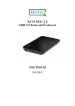
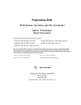
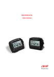
MXL2 Dash Logger
USER GUIDE
AiM Srl.
Via Cavalcanti, 8
20063 Cernusco S/N (MI)
Italia
Tel. (+39) 02.9290571
Made in Italy
www.aim-sportline.com
MXL2 Dash Logger
02
04
1. INTRODUCTION
06
2. WHAT IS IN THE KIT
08
3. LAYOUT AND PUSHBUTTONS
10
4. GEAR FLASHES AND ALARM LEDS
11
5. ECU CONNECTION
12
6. RPM
12
6.1 RPM FROM ECU
12
6.2 RPM VIA A 5-50 V SQUARE WAVE SIGNAL OR COIL (150-400 V)
14
7. SPEED
14
7.1 SPEED READ FROM ECU
14
7.2 SPEED READ FROM GPS RECEIVER
14
7.3 SPEED READ FROM WHEEL SENSOR
16
8. ANALOG INPUTS
17
9. DIGITAL OUTPUTS
18
10. RACE STUDIO 3 SOFTWARE
19
10.1 CONFIGURATION
21
10.1.1 DISPLAY CONFIGURATION
22
10.1.2 CHANNELS CONFIGURATION
23
10.1.3 ECU STREAM CONFIGURATION
23
10.1.4 ALARM LEDS, DIGITAL OUTPUT AND SHIFT LIGHTS
26
10.1.5 MODIFY OR DELETE AN EXISTING CONFIGURATION
27
10.2 CONNECT YOUR MXL2 TO A PC
27
10.2.1 CONFIGURING TRANSMISSION
28
10.2.2 ONLINE VIEW AND CALIBRATION
29
10.2.3 DATA DOWNLOAD
30
11. GPS AND TRACK MANAGEMENT
30
11.1 TRACK FEATURE
32
11.2 FILTERS IN TRACK DATABASE MANAGEMENT
34
11.3 HOW TO ADD A NEW TRACK TO THE PC DATABASE
36
11.4 HOW TO MODIFY TRACK DATA IN THE PC DATABASE
37
11.5 HOW TO READ, WRITE AND DELETE TRACK INFORMATION
39
EXPANSION
40
MXL2 PINOUT
42
TECHNICAL DRAWINGS
Thanks.
Dear Customer,
First, we would like to thank you for choosing
the MXL2 dash logger as the tool for
improving your racing craft setup and
on-track performance.
The MXL2, with its high contrast display,
advanced expansions and sampling
capabilities, gives you the flexibility for
reviewing your data in your preferred way
and recording them from a variety of
sensors and sources.
Please, before digging into your new data
system, keep in mind that we are constantly
working on bettering our software and
firmware.
So, be sure to check our website
periodically for any updates.
www.aim-sportline.com
03
CHAPTER 1
What is MXL2?
How do alarm LEDs
work?
MXL2 is a color, high-contrast brilliant
traditional LCD dash logger developed
for race car installations.
It is fully customer configurable.
You can configure alarm LEDs
choosing color, blinking frequency and
defining the logic for turning them on
or off.
Which data does it
manage?
What is it possible with
WiFi?
Data come from a wide range of sources,
including your vehicle ECU, the internal
accelerometers and gyro, the GPS
module included in the kit, the
analog/digital inputs, the external
expansions as well as predefined math
channels.
You can use a WiFi connection for
transmitting the data of your test,
sending data online and for
configuring the system.
How many pages does
it show?
You can define up to eight different
fully customizable pages.
Is it possible to configure
the pages?
You can choose among a wide library
of page styles, defining the data to be
shown. End of scales and units of
measure can be easily configured,
using the RaceStudio3 software
included in the kit.
04
Are the data recorded
by MXL2 compatible
with the old MXL and
EVO4 data?
Yes, MXL used to produce data in DRK
format. MXL2 offers an improved data
management and produces XRK
format that only RaceStudio3 can read.
Nevertheless, the last releases of
RaceStudio2 can detect XRK files and
transform them into old DRK format
files that are compatible with MXL1
and EVO4 files.
INTRODUCTION
What is the difference
between the old DRK
format and new XRK?
MXL2
We are going to upgrade it very often,
so, please, don’t forget to check our
web site at www.aim-sportline.com.
XRK, taking advantage of GPS
technology, associates absolute time
and GPS position to each data with the
precision of 1 millisecond.
In this way, it is possible to better
compare different laps and tests.
What about
RaceStudio3?
What are the
differences between
the old DRK format
and new XRK?
RaceStudio3 is the new software for
managing configuration, data
download and data analysis for all the
future AiM systems.
It is going to substitute RaceStudio2,
which has accompanied us for almost
15 years.
Based on a totally new and much more
flexible architecture, it is a work in
progress; some features still have to be
developed, so they are actually shared
with RaceStudio2.
05
CHAPTER 2
2. What is in the kit
The MXL2 kit includes:
06
MXL2 dash logger
Harness
GPS05 module
Software
WHAT IS IN THE KIT
MXL2
LAYOUT AND PUSHBUTTONS
CHAPTER 3
MXL2
MXL2 Dash Logger
Configurable Alarm LEDs 1-3
Shift Lights
Multifunctional Pushbuttons
08
Configurable Alarm LEDs 4-6
Motorsport Connectors
Aluminum Body
09
CHAPTER 4
GEAR FLASHES AND ALARM LEDS
CHAPTER 5
4. Gear Flashes and Alarm LEDs
ECU CONNECTION
MXL2
5. ECU connection
1
value at which to turn it on and the colour.
You can also define different RPM values of
each gear number.
MXL2 features 10 RGB gear flash LEDs that
can be freely configured in a very flexible
way. For each LED, you can define the RPM
1
2
2
MXL2 can acquire data from the ECU of
your vehicle.
The list of the ECU protocols available is
published on our site:
www.aim-sportline.com/download area,
ecus connections.
This list includes approximately 500
different protocols and is constantly
updated with new protocols and upgrades
published every week.
When possible, documents explaining how
to configure your ECU to ensure
compatibility between the data flow
transmitted are available, too.
The steps to manage the data coming from
the ECU are the following:
1. Determine which hardware connection
is available for your ECU.
2. Read the documentation about your ECU
at www.aim-sportline.com and identify the
name of the proper software driver to be
specified.
3. Using Race Studio 3, configure MXL2
setting your ECU driver with the menu
shown here below, that appears when you
create a new configuration.
From an hardware point of view, MXL2 is
compatible with all currently available
connections: CAN, RS232 or K line.
2
MXL2 also has 6 different alarm LEDs that
you can configure in order to turn them on
or off depending on the value of the analog
or digital inputs, ECU values, expansion
values, GPS information or math channels.
You can configure them in order to turn them
off when the condition disappears, when you
push a pushbutton, when the test is finished
or when the data are downloaded after the
test.
You can associate an alarm LED, a message
and a digital output with each event.
Please, read section 10.1.4 in order to see how
to manage gear flashes and alarm LEDs.
10
The ECU has to be set when configuring
your MXL2 with RS3 configuration
software.
The steps are explained in section 10.1.
11
CHAPTER 6
MXL2
RPM
6. RPM
MXL2 can receive the RPM signal from three different sources:
n From ECU
n Through a square wave signal (8 to 50 V)
n From the low voltage (from 150 to 400 V)
of the coil
6.1 RPM from ECU
The image shows an example of wiring for
the ignition system.
The output, labelled “GREY TACH” gives a
5-50V output that can be directly acquired
from MXL2 If the output is not available
from the ignition system, the system has to
be connected to the low voltage of the coil,
as shown in the following schematic.
To get RPM from the ECU please configure your MXL2 and enable RPM channel as explained
in section 10.1. RPM is one of the many data flowing from your ECU to MXL2.
6.2 RPM via a 5-50 V Square Wave Signal or coil (150-400 V)
2
In case your engine is not managed by any ECU, MXL2 can read the signal from the low voltage
of the coil (whose peak can be from 150 to 400 V) or from a possible square wave (the peak
can be from 5 to 50V). The pin labelled "RPM" reported in appendix “Pinout” receives the
signal:
1
2
1
3
3
Point 1: Low voltage of the coil
Point 2: Connected to the spark plug
Point 3: Connected to the +12V of the
battery
After connecting the RPM signal, please use
the software RaceStudio3 for enabling the
RPM channel, as explained in section 10.1.2
12
13
CHAPTER 7
SPEED
MXL2
7. Speed
MXL2 can receive the speed signal from
three different sources:
n From the ECU
n From the GPS receiver included in the kit
n From the wheel sensors
(digital channels)
It is therefore possible for MXL2 to receive
and store different values of speed at the
same time; the more powerful ECUs
transmit up to four wheel speed values.
7.3 Speed read from wheel sensors
MXL2 has four wheel speed inputs, one in
the 37 pins connector and the other three
in the 22 pins connector:
The digital sensor X05SNBS00 detects the
presence of a metallic tooth placed at a
distance between 0.5 and 2 mm.
7.1 Speed read from the ECU
If your ECU sends the value of speed in its
data stream, it is obviously possible to read,
record and show that value.
Simply enable its using in the software
RaceStudio3, as explained in section 10.1.
7.2 Speed read from the GPS receiver
The GPS receiver integrated in the MXL2 kit
is configured in order to obtain the best
performance in terms of reactivity and
accuracy.
For getting GPS speed, you don’t need any
configuration. Simply connect the GPS05
Module to your MXL2 and after a setup
period of some seconds, the data will be
received and automatically recorded.
14
Please use the software RaceStudio3 for
configuring the system.
Just enter the program configuration panel
and, after enabling the desired speed
channels, set the wheel circumference and
the number of pulses per revolution.
15
CHAPTER 8
ANALOG INPUTS
8. Analog Inputs
MXL2 has 8 analog inputs, recorded up to
1000 times per second each.
You can connect:
n 0-5 Volt signals
n Ratiometric potentiometers
n Pressure sensors
n Thermo-resistances
n K-type thermocouples
Please use the following steps, using the
software RaceStudio3 as explained in
section 10.1:
n Connect the sensor to the desired input
n Enable the channel in the Channels table
n Select the proper sensor type; sensors of
many different types are properly
handled
n Set the sampling frequency
n Set the unit of measure.
16
CHAPTER 9
n Temperature sensors
DIGITAL OUTPUT
9. Digital Output
K thermocouples
Thermo-PT100 resistors
Temperature sensors VDO
MXL2 features two digital outputs in the 22
pins connector.
n Pressure sensors
Each of them can give an output of 1 amp
at 12 volts.
You can configure them in order to turn
them on or off depending on the value of
the analog or digital inputs, ECU values,
expansion values, GPS information or math
channels.
VDO 40-120 ° C
VDO 50-150 ° C
VDO 60-200 ° C
MSI 0-2 bar
MSI 0-5 bar
MSI 0-10 bar
MSI 0-2000 psi
n Potentiometers
Distance
Zero-based
Zero Central
n Generic sensors
0-50 mV
0-500
0-5 V
MXL2
To each event you can associate an alarm
LED, a message and a digital output.
You can configure them in order to turn
them off when the condition disappears,
when you push a pushbutton, when the
test is finished or when the data are
downloaded after the test.
Please refer to section 10.1.4 in order to see
how to manage the digital outputs.
17
CHAPTER 10
RACESTUDIO3 SOFTWARE
MXL2
10. RaceStudio3 Software
RaceStudio3 is the powerful software that
you are going to use for all the activities regarding your MXL2. It offers the following
features:
MXL2 configuration:
Create, modify, delete, export and import
configurations with all Channels, ECU
drivers, Math channels, Display pages ,
Alarm, Digital outputs, Shift lights and all
the expansions.
When you start RaceStudio3 with your
MXL2 connected and switched on, you can
see a pushbutton in the upper left position
of the screen; this lets you swap between
different features:
n Configurations
n Tracks
n Analysis
n Movies
n Preferences
n Web Updates
Configurations
Creates, imports, exports and
modifies existing configurations.
Tracks
Creates, imports, exports and
modifies the map of your racing tracks.
Data analysis
For looking at and comparing your data.
Movies
For watching and comparing up to two
track laps.
Preferences
For setting software language and measure
units (pressures, speed, temperature, brake
and oil pressure).
Web updates
Downloads new firmware and software
releases from our site
www.aim-sportline.com to automatically
upgrade your MXL2.
RaceStudio3 software is provided on a CD
included in the MXL2 kit or can be
downloaded from Download area
of www.AiM-Sportline.com
18
10.1 Configuration
The configuration page is divided into two
sections.
The left side is dedicated to the folders that
you can create and manage in order to
better organize your configurations.
Simply push the [+] pushbutton in order to
create a new one.
When you connect an AiM logger, like your
MXG, its serial number appears in the left
side of your screen. In the right side of the
screen you can see all the configurations of
the selected folder. Please click on the
desired one for editing it or push the
“NEW” pushbutton for creating a new one.
19
CHAPTER 10
RACESTUDIO3 SOFTWARE
MXL2
10.1.1 Display Configuration
After selecting the DISPLAY configuration
feature, the following page appears:
Please don't forget to select the proper ECU
Manufacturer and model to which connect
your MXL2.
After having entered the MXL2
configuration page you can see different
tabs, which are useful for selecting one of
the following configuration features:
n Channels
n Ecu stream
n Shiftlights and Actions
n Display
20
It is divided into two different sections.
You can define:
On the right, you can select one of several
different layouts, while on the left you will
manage the different fields, selecting the
proper information to be shown, the
parameters, labels and the units of
measure.
n The channel,
n The label,
n The unit of measurement
n The end of scale for each channel shown
on the page (scale)
You can add up to eight pages.
Please use the lower left part of the display
for configuring each channel.
When the panel shows the desired
configuration, push “SAVE” or “CLOSE” for
saving the configuration.
In case you have connected your MXL2 to
the PC, the “TRANSMIT” pushbutton is
available for transmitting the new
configuration to your device.
21
CHAPTER 10
RACESTUDIO3 SOFTWARE
10.1.2 Channels Configuration
10.1.3 ECU Stream Configuration
Push the tab CHANNELS:
With this feature, you can enable or
disable the data coming from your ECU,
and you can define.
MXL2
n The name
n The sampling frequency
n The measure unit
n The measure precision
The channel configuration page will appear
With this page you can define all the parameters for your analog inputs, speed inputs and
digital RPM input.
10.1.4 Alarm LEDs, Digital Output and
Shift Lights
Click “Shift Lights and Actions” for
managing the Shift Light LEDs, Alarm LEDs
and Digital Outputs.
By clicking on each line, a menu appears:
You can define:
n The name of the channel
n The function
n The sensor connected
n The sampling frequency
n The measure unit
n The measure precision
n The measure filter level
22
23
RACESTUDIO3 SOFTWARE
MXL2
Alarms Configuration
When you click “Add new trigger” the
window shown in the above picture
appears. There you can define the event
the system has to check and the effect of
that event.
There are some options:
n Until when the condition is no longer met
n Until when the device is turned OFF
n Until when a button is pushed
n Until when data is downloaded
1) Fill the DESCRIPTION field, in order to
easily identify the event in the future.
2) Describe the Alarm: it can be a simple
event, like, for example:
“Water temperature is higher than 100 C”
or a combination of multiple events, like,
for example:
Shift Lights Configuration
Using the configuration bar you can
manage, for each LED the color and RPM
threshold value that will turn it on.
Pushing the pushbutton “Option” you can
decide:
Once the configuration is set, a summary
will appear: any time you need to change
settings, just click on the icon and proceed.
The icon at the left recalls the condition you
chose to turn the LED off.
“Water temperature is higher than 100 C”
and “Engine RPM is higher than 6000”
You can add different check lines and
define the alarm as a combination of ALL
the events or just ONE of them.
3) Describe what to do when an alarm
arises: MXL2 can:
4) Turn a LED ON: You have to select the
color and the behaviour (fast/slow blinking
or continuous).
To keep the LED ON if its threshold is
exceeded or to keep the LED ON only until
another LED is turned ON.
5) Show a TEXT MESSAGE that you have to
create and define.
And if the LEDs are managed according to
the engaged gear number.
6) Finally, you have to configure till when
the alarm has to remain in evidence.
In this case, for each gear number you have
to define the levels at which to turn them
on.
24
25
CHAPTER 10
RACESTUDIO3 SOFTWARE
10.1.5 Modify or Delete an Existing
Configuration
10.2 Connect Your MXL2 to a PC
For modifying an existing
configuration, select the desired configuration
to be modified and double click on it.
When you connect your MXL2 to the PC, it
is automatically recognized, and on the left
side of the PC display the name of your
device appears, as shown in the picture.
At this point, you can execute the following
functions:
To delete an existing configuration, click on
it and select delete.
MXL2
n Transmit the configuration
n On Line view
n Calibration
n Data download
Then, proceed like in the creation of the
configuration.
This is explained in the next paragraphs.
10.2.1 Configuration Transmission
When you connect an MXL2 to your PC, the
“TRANSMIT” pushbutton appears at the
top of the configuration page.
Simply push it and the configuration will be
transmitted.
26
27
CHAPTER 10
10.2.2 On Line View and Calibration
Push “LIVE MEASURE” for looking at the
data coming from your MXL2.
You can change the measure of unit by
double-clicking on the measure.
From the Online View, you can calibrate
the channels that require calibration.
28
RACESTUDIO3 SOFTWARE
MXL2
10.2.3. DataDownload
Push “DOWNLOAD” for downloading the
data recorded in your MXL2.
You will see the information about the files
recorded in the system: dimension and
date/time of the file creation.
Please select a file and push
“DOWNLOAD” for transferring it to your
PC.
29
CHAPTER 11
MXL2
GPS
11. GPS and Track Management
The GPS Module, included in the MXL2 kit,
provides the following information,
updated ten times per second:
n Position (latitude, longitude, altitude)
n Speed
n Longitudinal acceleration
n Lateral acceleration
If MXL2 knows the finish line of the track
and the split coordinates, it can
calculate and show:
n Lap Times
n Split times
To transmit track information to MXL2, use
the Track Manager feature, as explained in
the following section.
30
11.1 Tracks Feature
1
With Tracks you can update, modify,
transmit and receive to and from MXL2 the
coordinates of the finish line and split
points of all the tracks you are going to run.
When opening the software, if there is no
system connected to your PC via USB cable,
you will see the screen shown here on the
right.
2
3
4
5
8
7
As you can see, the screen is divided into
two parts.
On the left you see the track list.
If available, you will see the track layout and
the type of vehicle that usually races on the
track: car, motorcycle or kart.
On the right side of the screen, you will find
a big picture of the track.
1
Static filter button
2
Selection window for dynamic filters
3
Track type: car, bike, karts
4
Track setting
5
Track shape, with starting line
and split points position
6
Small track shape
7
Track selection check box
8
View/hide country tracks
6
31
CHAPTER 11
11.2 Filters in Track Data Base
Management
You can filter the list of tracks you need in
different ways.
The filters can be static (1) recorded and
used every time you use Track Manager, or
dynamic (2) not saved when quitting the
program.
1
GPS
MXL2
Static Filters
A static filter is activated by the button
“filter” [1].
The window shown here on the right
appears.
2
It allows you to select nations, type of
vehicle and type of circuit.
The lists shows only countries, vehicles and
types of circuits present at least once in the
database.
For example, if the database does not
include any track in Germany, this country
will not appear in the list.
By default, all countries, types of vehicles
and tracks are enabled.
If you are interested in only the car tracks,
for example, you must disable karts and
motorcycles.
Dynamic Filters
The dynamic filters are activated by the top
left box of the screen [2]:
The dynamic filters allow you to further
filter the tracks by merging different
characteristics.
For example, when writing "Spain kart,"
you will see only kart circuits in Spain.
32
33
CHAPTER 11
MXL2
GPS
11.3 How to Add a New Track to the PC
Database
The official AiM track Database is
continuously growing. To update your PC
database, you can import the new tracks:
You can now select the “.GPK” file
containing the GPS map of your track
session.
Please select the proper file, carefully
checking the name, date and time of the
files.
Press “Options” then“Import Tracks from
AiM Website”.
To add a new track:
1) Press the button “New.”
1
Map of Your Track Session
2) Enter the name of the track.
2
After having selected the desired lap, push
“OK” to save the image of that lap.
That image will be used as a reference
shape.
3) Enter the required information:
Track name, Nation, type of circuit (closed,
oval or point to point) and surface
(asphalt, dirt, ice, mixed or water).
Finally, using the icon buttons, set the type
of vehicle that usually runs on the circuit:
cars, motorcycles or karts.
If you have already run a test on the track
and have downloaded data, you can
associate the shape of the track by pressing
“Load Shape” button.
34
The shape of the track appears, split in
different laps of the test. Using the
keyboard highlighted here on the right it is
possible to scroll through the different laps,
zoom and rotate the drawing (4).
Finish line coordinates are automatically
calculated but can be modified as desired
in one of the following ways:
4
3
Filling in latitude and longitude (5).
Placing the cursor on the desired point of
the track and clicking the “Cursor Pos”
button. (6).
In case of a point-to-point track, it is
necessary to define the coordinates of the
starting and finish line. Push “OK” to save
the configuration.
5
6
35
CHAPTER 11
GPS
11.4 How to Modify Track Data in the PC
Database
11.5 How to Read, Write and Delete
Tracks Information in MXL2
Click the setting icon show here on the right.
Connect your system to your PC using the
USB cable.
The window containing the track data will
open.
36
MXL2
The Track Manager screen will display two
lists. On the left are the tracks in your PC
and on the right are the tracks in MXL2.
37
CHAPTER 11
GPS
MXL2
CHAPTER 12 EXPANSION
12. Expansion
To transmit track information to MXL2
To receive track information from MXL2
Select tracks to be submitted by clicking on
the square check box or on the name of the
track.
Select tracks to be submitted by clicking on
the square check box or on the name of the
track.
Drag in the right panel or press button
Drag in the left panel or press button
8 Analog Inputs
The tracks’ information is updated in the
SmartyCam panel.
Tracks’ information is updated in the PC list.
4 Speed Inputs
Memory Module
SmartyCam HD GP
Channel Expansion
GPS05 Module
Lambda Controller
ECU
Modular Data Acquisition System
Using our built in CAN bus, add expansion modules like GPS, external memory modules, channel
expansions, lambda controllers. These are only some of the items that can be added to our
MXL2 range for incrementing the performance and the data acquired.
38
39
CHAPTER 13
MXL2
MXL2 PINOUT
13. MXL2 Pinout
PIN
01
02
03
04
05
06
07
08
09
10
11
12
13
14
15
16
17
18
19
20
21
22
23
24
25
26
27
28
29
30
31
32
33
34
35
36
37
Deutsch 37pin.
9-15V power in
gnd batt
can+ Exp
gnd
+Vbatt can
can- Exp
+Vbext
Can1+ Ecu
Can1- Ecu
gnd
k line Ecu
USB D+
USB Dgnd
rpm
gnd
+Vbatt
Optical lap
speed1
gnd
+Vbatt
Ain1
gnd analog
+Vbatt
+Vref
Ain2
gnd analog
+Vbatt
+Vref
Ain3
gnd analog
+Vbatt
+Vref
Ain4
gnd analog
+Vbatt
+Vref
PIN
01
02
03
04
05
06
07
08
09
10
11
12
13
14
15
16
17
18
19
20
21
22
Motorsport Connectors
Deutsch 37pin.
40
Deutsch 22pin.
Ain5
gnd analog
+Vbatt
+Vref
Ain6
Ain7
gnd analog
+Vbatt
+Vref
Ain8
speed2
gnd
+Vbatt
speed 3
speed4
gnd
Can2+ Ecu
Can2- Ecu
Dout1
Dout2
rs232 TX Ecu
rs232 RX Ecu
Deutsch 22pin.
41
CHAPTER 14
1.2
187.8
MXL2 TECHNICAL DRAWINGS
1.2
16
103
MXL2
15.9
21
66.4
149.9
2.5
4xM4
- Display
- Backlight
- Ambient Light sensor
- Alarm LEDs
- Shift Lights
- CAN connections
62.7
- ECU connections
- ECU compatibility
- External modules connection50.3
- Expansion CAN connection
- Connectors
- Analog inputs
- Digital inputs
- Digital outputs
- Accelerometer
- Internal memory
- Body
- Pushbuttons
- Dimensions
- Weight
- Power consumption
- Waterproof
42
21.6
LCD display + graphical portion
White or red
Yes
48.4
6 RGB freely configurable
10 RGB LEDs freely configurable
35
3
CAN, RS232 or OBDII
+500
20.6 industry leading ECUs
38.5
30
62
Yes
DIMENSIONS IN mm
GPS, Channel expansion, Lambda Controller, SmartyCam
2 Motorsport connectors
8 fully configurable, max 1.000 Hz each
4 speed inputs , lap signal, coil RPM input
2
Internal Three-axial ± 5G+Gyroscope
4Gb
Anodize Aluminum
Metallic
187,8x103x21mm
530g
400mA
IP65
Our web site aim-sportline.com is constantly
updated.
Please, check it frequently and download
the latest versions of the firmware of your
products.
43