1
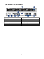
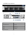
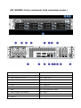
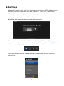
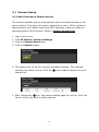
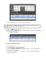
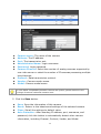
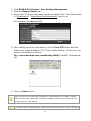
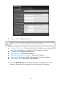
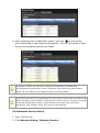
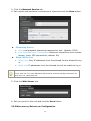
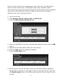
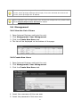
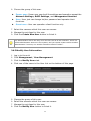
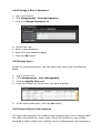
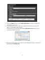
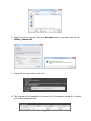
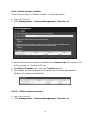
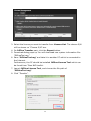
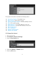
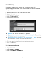
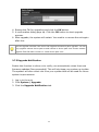
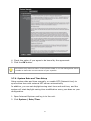
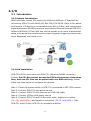
The Intelligent Surveillance Solution Titan NVR Server User Manual Ver. 1.5.0.121029.00 Table of Contents 1. Installation ...................................................................4 1.1 Installation Process .....................................................4 1.2 LED Status Definitions ............................................... 15 2. Settings ..................................................................... 17 2.1 Camera Setup ........................................................... 18 2.1.1 2.1.2 2.1.3 2.1.4 Add Cameras by Camera Search........................ 18 Add Cameras Manually ..................................... 19 Modify Camera Information .............................. 21 Modify Camera Parameters ............................... 21 2.1.5 Set up Lens Settings ........................................ 21 2.1.6 Set up 2nd Stream .......................................... 22 2.1.7 View Camera Status ........................................ 24 2.2 Recording & Event Setup ............................................ 25 2.2.1 Recording Mode Setup ..................................... 25 2.2.2 2.2.3 2.2.4 2.2.5 2.2.6 2.2.7 2.3 RAID 2.3.1 2.3.2 2.3.3 2.3.4 2.3.5 2.3.6 Recording Schedule / Event Setup ..................... 26 Camera Events and Responding Actions Setup .... 30 I/O Box Input and Responding Action Setup........ 32 System Events and Responding Actions Setup ..... 32 SMTP Server Setup .......................................... 34 Add Event Contacts ......................................... 35 & File Settings .................................................. 35 Create a RAID Volume ..................................... 35 View RAID Volume Status ................................. 37 View Disk Drive Information ............................. 38 Modify RAID Volume ........................................ 39 Delete a RAID Volume ...................................... 41 Format ........................................................... 42 2.4 Auto Backup ............................................................. 42 2.4.1 Set up Backup Schedule ................................... 43 2.4.2 Set up Backup Server ...................................... 43 2.5 Network Setup .......................................................... 45 2.5.1 View Network Status ........................................ 45 2.5.2 2.5.3 2.5.4 2.5.5 Network Settings ............................................. 45 Auto Port-Forwarding ....................................... 47 Network Service Setup ..................................... 48 Main server/Sub server Configuration ................ 49 1 2.6 Management............................................................. 51 2.6.1 View the List of Users ...................................... 51 2.6.2 2.6.3 2.6.4 2.6.5 2.6.6 Create New Users ............................................ 51 Modify User Information ................................... 52 Change a User’s Password ................................ 53 Delete Users ................................................... 53 Import/Export User Account ............................. 53 2.6.7 Online License Activation .................................. 54 2.6.8 Offline License Activation .................................. 55 2.6.9 Online License transfer ..................................... 58 2.6.10 Offline license transfer .................................. 58 2.6.11 View the Event Log ....................................... 60 2.6.12 Save Unit Configuration ................................ 62 2.6.13 Load Unit Configuration / Default Settings ....... 62 2.7 System .................................................................... 63 2.7.1 View System Information ................................. 63 2.7.2 2.7.3 2.7.4 2.7.5 Smart Fan Control ........................................... 64 UPS Setup ...................................................... 65 Upgrade the System ........................................ 65 Upgrade Notification ........................................ 66 2.7.6 System Date and Time Setup ............................ 67 2.7.7 Local Display................................................... 68 2.7.8 Restart the Unit ............................................... 70 2.7.9 Shut Down the Unit ......................................... 70 I/O ............................................................................ 72 3. 3.1 Introduction ............................................................. 72 3.1.1 System Introduction ........................................ 72 3.1.2 HW Installation ............................................... 72 3.1.3 Software Installation – SCB-C31........................ 73 3.1.4 Software Installation – SCB-C24/26/28 .............. 74 3.2 Software Setup ......................................................... 76 3.2.1 Add I/O Box .................................................... 76 3.2.2 Modify I/O Box Information .............................. 77 3.2.3 I/O Pin Setting ................................................ 77 3.3 Relative Configuration and Application ......................... 78 3.3.1 Record on Input Trigger.................................... 78 3.3.2 Input and Responding Actions ........................... 78 3.3.3 I/O Control Panel in Live View ........................... 78 2 4. External Storage ......................................................... 79 4.1 Create a Volume on DAS ............................................ 79 4.2 4.3 Create an External Storage ......................................... 79 Create an External Storage on iSCSI............................ 80 Log out ...................................................................... 82 Remote PC System Requirements .................................. 83 Troubleshooting .......................................................... 84 7.1 7.2 7.3 7.4 Replace a Failed Disk Drive ......................................... 84 Respond to a Critical RAID Volume .............................. 84 Respond to a File System Error RAID Volume ................ 84 Install ActiveX........................................................... 84 5. 6. 7. 7.5 Cannot Log in to the Unit with Internet Explorer ............ 85 Appendix – RAID System......................................................... 86 Introduction to RAID ......................................................... 86 RAID 0 – Stripe ................................................................ 86 RAID 1 – Mirror ................................................................ 87 RAID 5 – Block Striping with Distributed Parity ..................... 88 RAID 10 – Mirror / Stripe ................................................... 88 Choosing a RAID Level ...................................................... 89 Appendix – Camera Integration ................................................ 91 Camera Support List ......................................................... 91 3 1. Installation 1.1 Installation Process Step 1: Unpack the Unit This package contains the following items: The unit Quick Start Guide Screws for disk drives Key Power cord Warranty card CD with Install Wizard, NuClient and Offline License Tool application, user manual, and quick start guide The electronic components within the unit can be damaged by Electrostatic Discharge (ESD). Please take precautions at all times when handling the unit or its sub-assemblies. To configure the unit, you must install the software onto a desktop/ laptop running Windows XP-SP3 32bit, Windows 7 32/64bit, Mac OS X v10.6/10.7 Unit front/rear view (NT-4040:Tower) 4 (NT-4040R: 4 bay rackmount) 1. Key Lock 7. VGA 2. LED Indicators: Power, LAN1-2, HDD1–4 8. eSATA Connector 3. USB x2 9. USB x 4 4. Power Button 10. Gigabit LAN x 2 5. PSU Cooling Fan 11. Main Cooling Fan 6. Power Connector 5 (NT-8040R: 8 bay rackmount) 1. LED Indicators: LAN2 10. Power bottom 2. LED Indicators: LAN1 11. Line-in 3. LED Indicators: Power 12. Line-out 4. Key lock 13. Microphone in 5. eSATA Connector 14. USB 3.0 x2 6. Lan 2 15. USB 2.0 x2 7. Lan 1 16. DVI 8. VGA 17. COM port 9. Power supply switch 6 (NT-8040RP: 8 bay rackmount with redundant power) 1. LED Indicators: LAN2 12. Line-out 2. LED Indicators: LAN1 13. Microphone in 3. LED Indicators: Power 14. USB 3.0 x2 4. Key lock 15. USB 2.0 x2 5. eSATA Connector 16. DVI 6. Lan 2 17. COM port 7. Lan 1 18. LED Indicators: PSU1 8. VGA 19. LED Indicators: PSU2 9. Power supply mute bottom 20. PSU1 10. Power bottom 21. PSU2 11. Line-in 7 Step 2: Install Hard Drives Refer to compatibility list and install HDDs. For optimal performance consideration, install disks with the same model and storage capacity. The available RAID level depends on the amount of disks installed. 1. Open the lid on the front of the unit enclosure. 2. Pull a HDD tray from the enclosure. See the front view figure. 3. Carefully lock the disks into the HDD tray with screws. 3 screws for each disk. We recommend locking the screws on the bottom of the disk, instead of the side of tray. Put the HDD tray back once you finished. Step 3: Connect to the Network 1. Attach one end of the network cable to the RJ45 network connection. See the rear view figure. 2. Attach the other end of the network cable to your Ethernet hub or switch. If there are multiple networks at your facility, note the network to which you connect the unit. You will need this information during the setup process. Please also enable the DHCP function within the network, as the unit will retrieve an IP address through DHCP by default. Step 4: Connect the Power 1. Attach the power cord to the power source. 2. Connect the power cord to the back of the unit enclosure. See the rear view figure. 3. On the front of the unit, press the power button. See the front view figure. It takes about a minute for the unit to fully power up. Once it is powered up, the Power Status LED turns blue. See the front view figure. Step 5: Install the Software 1. Insert the CD into your CDROM. 2. Double-click Setup.exe to begin installation. 3. Follow the instruction of Setup.exe, and click the Finish button to close 8 the installer. Step 6: Set up the Unit The software Installation Wizard performs the setup procedures on the unit. After the procedure, you can begin using it. 1. Go to Start > NUUO Titan Series > NUUO Install Wizard. 2. This program will show the default language setting and initiation mode. 3. Choose your preferred language and initiation mode, and then click the button. Express Mode: you don’t need to set up the network settings and RAID level. Advanced Mode: configure all settings manually: network, license, camera, Date/Time, upgrade notification, and RAID level 4. The Installation Wizard program starts searching for all the units on the internet currently. Choose one of them, and then click the 9 button. 5. Type in the password, and then click the OK button. The default Administrator password is “admin”. 6. Name this server and select the network type, and then click the button. 10 Obtain network settings automatically from external DHCP server: apply all settings which are automatically generated by the DHCP server, such as IP, subnet mask, gateway, and DNS. Configure network settings manually: configure the preferred settings one by one. 7. Activate camera license to have more channel capacity, and click the button. 8. Add cameras for this server. There are two ways of adding cameras, 11 selecting the searched cameras and manually configuring the cameras. Click the button after completing camera list. Click the Search button. Select camera and type the camera name, username and password. 12 Add cameras manually. 9. Set up the time zone, date, and time, and adjust daylight saving changes if needed. Once daylight saving function is enabled, the time change will activate automatically every year based on the recurrence you set. Click the button. 10.Check “Enable Upgrade Notification” box if you want to receive notification when there is a newer FW version. Click the 13 button. 11.Follow the following instruction and select the RAID type you want to create. Click the button. 12. Review your settings. If the settings are correct, click the Finish button to exit the settings procedure and activate the system. 14 Once the “FINISH” button is clicked, the unit will start working. In order to ensure the stability of the unit, never pull any disks out when the system is running. 1.2 LED Status Definitions NT-4040R Function LED Status Power Status Power-on: blue Power-off: dark HDD Status (top) Power-on: blue Power-off: dark HDD Activity Status Healthy: blue with blinking (bottom) No disk: dark Ethernet Status Linking: blue Accessing: blue with blinking No linking: dark NT-8040R Function LED Status Power Status Power-on: blue (front) Power-off: dark Remark Power standby(power-on, but Titan not operate): blink slowly 15 HDD Status Power-on: blue Two LEDs on HDD tray (front; HDD Power-off: Dark LED1: power and access Tray) Access: blink (Blue) indicator LED2: reserved, no status Ethernet Status Connected: blue Two LED, one for LAN1 x2 Accessing: blue with blinking status and the other one (front) Ethernet Activity for LAN2 status Link Rate indicator (Left side) x2 1) Green =1000M (rear) 2) Orange=100M 3) Dark=10M or no link Link status indicator(Right side) 1) Accessing: Green with blinking 16 2 LEDs for each Ethernet port 2. Settings After setting up the unit, log in to the system by entering its IP address in the browser (Internet Explorer 8 and later, Safari 5.1 7534.48.3, and Firefox 7.0.1). When connecting, choose your language, enter the user name and password, and then begin using this system. Take IE as the demonstration browser of this manual. There are four main functions of this unit: Settings, NuClient, Help Page, and Logout button. They will be shown on the top of the page. Currently, NuClient is supported on IE and Firefox only. Current firmware version and free storage capacity are shown above the function list. 17 2.1 Camera Setup 2.1.1 Add Cameras by Camera Search The function enables user to automatically search and add cameras in the same network. There are two search mechanisms, one is UPnP, another is camera search tool. Before searching UPnP cameras, make sure that the cameras possess UPnP function. Refer to camera support list. 1. Log in to the unit. 2. Click IP Camera/ Camera Settings. 3. Click the Camera Search tab. 4. Click the Search button. 5. The system will list all the currently available cameras. The inserted cameras are shown in blue. Click the camera list. icon to add a camera into your 6. After clicking the icon, the camera setting page will pop up. Click the item to which you want to add a camera. 18 7. Insert the camera name, user name, and password. To have better compatibility between camera and system, please make sure the privilege of camera credential is admin-level. 8. Click the Add button to add it. 9. After clicking the Add button, the updated camera list will be displayed in the Camera Setting tab. 2.1.2 Add Cameras Manually 1. Log in to the unit. 2. Click IP Camera / Camera Settings. 3. Click the Camera Settings tab, and the camera list will be displayed on the bottom of the page. 4. Click on the camera list for the channel you want to add and enter the camera’s information. 19 Camera name: The name of the camera. Address: The IP address. Port: The transmission port. Administrator Name: Login username. Password: Login password. Camera Channel: Select the number of analog cameras supported by one video server or select the number of IP cameras possessing multiple lens/channels. Protocol: Data transmission protocol. Vendor: Camera vendor name. Model: Camera model name. To have better compatibility between camera and system, please make sure the privilege of camera credential is admin-level. 5. Click the Save button. Save: Save the information of this camera. Reset: Return to the latest saved settings of the selected camera. Clear: Set all the settings to default value. Auto Detection: After inserting IP address, port, username, and password, click this button to automatically detect other camera information, including Channel, Protocol, Vendor, and Model. 20 2.1.3 Modify Camera Information 1. Log in to the unit. 2. 3. 4. 5. 6. Click IP Camera / Camera Settings. Click the Camera Settings tab. Click the camera which you want to modify. Modify the information of this camera. Click the Save button. 7. Use the same method to replace a camera if needed. 2.1.4 Modify Camera Parameters 1. 2. 3. 4. 5. Log in to the unit. Click IP Camera / Camera Parameters. Click the Camera Parameter tab. Click the camera which you want to modify on the camera list. Modify the information of this camera. 6. Click the Save button. Camera Name: The name of the camera. Video Format: Choose the type of format which this camera supports. Frame rate: Select the frame rate of the camera. Resolution: Select the resolution of the camera. Quality: Select the image quality of the camera. Audio: Check the Enable Audio option to view and enable audio recording. 2.1.5 Set up Lens Settings 1. Log in to the unit. 2. Click IP Camera / Camera Parameters. 21 3. Click the Lens Settings tab. 4. Click the camera which you want to modify in the camera list. 5. Modify the information of this camera. 6. Click the Save button. Camera Name: The name of the camera. Lens type: There are two types of lens currently, ImmerVision and Vivotek (FE8171V). You are not allowed to select type so far, type depends on camera model. ImmerVision Lens: Enable the option if ImmerVision lens is installed. VIVOTEK Fisheye camera: If you choose VIVOTEK fisheye camera, the lens type will be VIVOTEK and the status is enabled. Camera Position: Select the position of the camera. If users enable the lens while lens is not installed correctly or not even installed, a warning message will pop up as a notification if users are trying to operate lens on liveview page. 2.1.6 Set up 2nd Stream Stream profile is designed for mobile client and lower fps live stream display. Without stream profile integration, users cannot watch live video on mobile client nor select lower fps stream on liveview. Further, for performance consideration, we fix the resolution and framerate for each brand/series. Refer to camera support list. 1. Log in to the unit. 22 2. Click IP Camera / Camera Parameters. 3. Click the 2nd Stream Settings tab. Stream Profile: The default status is Disable. If you want mobile client user to access to this camera, you can select Enable, and click Save button in the middle of the page. Low Profile: The stream profile, under 300kbps, is designed for mobile client single-view. Minimum Profile: The stream profile, under 100 kbps, is designed for mobile client multi-view. Once you enable stream profile for the camera, you can choose video profile on client tool bar. 23 2.1.7 View Camera Status 1. Log in to the unit. 2. Click IP Camera / Camera Status. Conn. Status: The status of the connection. Click the Connect or Disconnect button to change the connection status. Status Icon Connection Status Connected Connection Status Disconnected Connection Status Connecting Connection Button Connected: Normal Connected: Over Connection Button Disconnected: Normal Disconnected: Over Rec. Status: The set recording schedule of this camera in this time. Status Recording Status Icon No Recording 24 Recording Status Recording Status Always Recording – Stopped Recording Status Schedule Recording – Recording Recording Status Schedule Recording – Stopped Recording Status Manual Recording – Recording Recording Status Always Recording – Recording Manual Recording –Stopped Framerate: The frame rate of this camera. Bitrate: The transmission bit rate of this camera. If your total bitrate becomes red, it means that the loading of the system is too heavy. 2.2 Recording & Event Setup 2.2.1 Recording Mode Setup 1. 2. 3. 4. Log in to the unit. Click Recording & Event / Recording settings. Click the Recording Mode tab. If selecting Always Recording, the chosen cameras will begin to record immediately. No Recording: Turn off the recording. Recording by Schedule: Recording by schedule. Always Recording: Permanently turn on the chosen cameras. 25 System will do recycling automatically when disks are full. 2.2.2 Recording Schedule / Event Setup Instead of Always Recording, you can begin the recording by setting the Recording Schedule. 1. 2. 3. 4. Log in to the unit. Click Recording & Event / Recording Settings. Click the Recording Schedule tab. Check the Day or Week mode. Day: Schedule the recording to turn the recorder on and off at the same time every day according to your setting. Week: Schedule the recording for each day of the week differently. 5. Click the schedule of the camera which needs to be modified. 6. Click the column at the bottom of the page. Insert: Insert new schedules. Delete: Delete the selected schedule. Configure: Modify the schedule and recording mode settings. Copy: Copy current Day Schedule to other channel(s); copy current 26 Week Schedule to other day(s) of a week or to other channel(s). 7. The default setting of the camera’s recording schedule is from 00:00 to 24:00. If you want to modify the time slot, click the Configure button to modify the default settings first. 8. Choose the recording mode. 27 Always Record: Always record. Record on Event: Record when events triggered. The event can be triggered by Motion or Digital input. When setting the event Motion, please first ensure that the motion detection function of the camera has been enabled. 9. If you want to add another new schedule, click the Insert button to add a new one. 10. Click the Save button. When changing the motion detection settings of a camera, make sure to disconnect your unit and that camera first. Once you have finished, re-connecting them will 28 update the settings in your unit. When setting an event, Motion or Digital input can be triggered from other cameras. This means that if the system detects motion or digital input from other cameras or I/O Box, the camera will begin recording. There is another way to set the schedule. If you want to change the recording time length, drag the end of the time bar from 24:00 back to the length you wish, and then drag the beginning of the time bar to the point at which you would like it to commence recording. (You may also click the Insert button to add new schedules.) 29 2.2.3 Camera Events and Responding Actions Setup 1. Log in to the unit. 2. Click Recording & Event / Event & Action Management. 3. Choose the camera, and then select one of the events. The event list depends on camera its own ability. Connect lost: When a connection between the camera and this unit is lost, the system will trigger an action. Motion from Camera: When video motion is detected, the camera triggers an action. Input: Any external input can trigger an action. 30 When setting the event Motion from Camera, make sure to set up the camera’s motion detection function first. Besides, event log will be recorded only if event is selected on this page. 4. Click the Configure button to enable the event and select the active period. Always Active: The selected event is always active. Active only in the following period: The selected event is only active in the designated time, which able to cover two days e.g. from 18:00 to 09:00. I/O Type: Check one of the options of I/O type. N/O means normal open, while N/C means normal close. 5. Click the Add button to set up the responding actions of this event. Output: When an event occurs, the system will send an output signal to other connected devices. E-Mail: When an event occurs, the system will send e-mail notifications. Make sure to add an e-mail address first. 31 6. Click the action, and then click the Configure button to modify the details of that action if necessary. 7. Click the Save button. After selecting camera events, the event information will display on the screen when it’s triggered. 2.2.4 I/O Box Input and Responding Action Setup 1. Log in to the unit. 2. Click Recording & Event / Event & Action Management. 3. Select an input of I/O Box from list. 4. Click the Add button to set up the responding actions of this event. 5. Click the action, and then click the Configure button to modify the details of that action if necessary. Output: When an input is triggered, the system will send an output signal to other connected devices. E-Mail: When an input is triggered, the system will send e-mail notifications. Make sure to add an e-mail address first. 6. Click the Save button. 2.2.5 System Events and Responding Actions Setup 1. Log in to the unit. 2. Click Recording & Event / Event & Action Management. 3. Click the Event & Action tab. 4. Click System to unfold the list of system events, and then select one of the 32 five events. Abnormal disk status: When there is no enough disk space for recording or when disk is abnormal for accessing, the system will trigger an action. Daily system report: Enable users to know the system information, HDD usage, and Disk status everyday through E-mail without accessing to the unit to check. Unable to access FTP: The action will be triggered when the connection between the unit and FTP server is lost. Backup unfinished: If there is any file which the system didn’t complete the backup process, the file(s) name will be listed and send out through E-mail after finishing the last file of this backup schedule. Power-on notification: Record the time as power was turning on. Auto power-off notification (overheat): Turn off the system power automatically to protect the unit from damage when it’s overheated. 5. Click the Add button to set up the responding actions of this event. Follow the steps in the previous section. 6. Click the Save button. E-Mail is the only one action to the event Daily system report, Unable to access FTP, Backup unfinished, Power-on notification and Auto power-off notification (overheat). In addition to select a contact, remember to insert the time of sending daily system report. 33 2.2.6 SMTP Server Setup 1. Log in to the unit. 2. Click Recording & Event / E-Mail. 3. Click the SMTP Server tab. Server Address: SMTP (Simple Mail Transport Protocol) server IP address. Port: SMTP port. Sender: Sender information. Subject: The subject of the mail. Body: E-Mail content. SMTP Authentication: Before sending out an E-Mail, enter the user name and password for SMTP authentication. Username Password 4. Click the Send Test Mail button and the system will send a test mail to the sender. Check it after testing. 5. Click the Save button. 34 2.2.7 Add Event Contacts 1. Log in to the unit. 2. Click Recording & Event / E-Mail. 3. Click the Contactors tab. Add Contactor: Add this new contact into the contact list. Reset: Return to the latest saved settings of the contact list. Save: Save this time modification of the contact list. 4. Insert the name of a new contact. 5. Insert the e-mail address of this new contact. 6. Click the Add Contactor button. 7. Click the Save button to save this modification of the contact list. 2.3 RAID & File Settings 2.3.1 Create a RAID Volume In this system, the term RAID volume refers to one or more disk drives working together as a RAID logical drive. You must create a RAID volume before starting to record. The maximum volume size to create RAID on Titan NVR is 16TB. Please make sure every volume you are going to add as a external storage is under 16TB. NT-8040R and NT-8040RP are 8 bay models. If your internal storage is over 16TB (for example, you use 3TB hard disk for all 8 bays, it will be 24 TB for internal storage), please create 2 volume for internal storage. 35 1. Log in to the unit. 2. Click RAID & File System / RAID Management. 3. Click the Create tab. 4. Choose the RAID level you prefer for your disk array. 5. Check boxes of disks and click the >> button to assign disk drives for this volume. 6. Click the Create button. 7. A confirmation dialog pops up. Check the Yes, I want to create volume with those disk(s) box, and click the Yes, create it button. 8. Creating RAID volume takes a while, depending on the size of disks and the RAID level you choose. You can start recording during RAID creation. 36 The RAID Volume will be functional on another unit if all disks of this volume are moved to the unit. After setting RAID level, you are not allowed to change neither the RAID level nor the number of disks containing in this volume. If you choose Express Mode when using the Installation Wizard, the disk(s) will be set to RAID 1 (2 bay) or RAID 5 (4 bay) automatically unless the number of disks is not enough for this RAID level. 2.3.2 View RAID Volume Status RAID status refers to the disk drives on your unit and how they are arranged into a RAID volume. 1. Log in to the unit. 2. Click RAID & File System / RAID Management. 3. Click the RAID Status tab to view the status of your RAID Volume. 37 RAID Name: Name of your RAID, automatically assigned when it was created. RAID Level: RAID 0, 1, 5, or 10, specified when it was created. RAID Status: Functional is normal. Critical means there are some problems on RAID volume, but the recording status is normal. Offline means that no volume is found, so recording is stopped and you cannot access your data either. File system error means that RAID volume is existed but not mounted, so recording is stopped and you cannot access your data either. Capacity: Total, free, used data capacity of the RAID volume. Update Time: The time of volume created/updated. Devices: Total number of disks and the number of active, failed, spare disks. Format Progress: The status of RAID format Recovery Progress: The status of RAID recovery 2.3.3 View Disk Drive Information 1. Log in to the unit. 2. Click RAID & File System / RAID Management. 3. Click the RAID Status tab. 4. Click on a disk directly to view the information. 38 2.3.4 Modify RAID Volume This function is designed for replacing a broken hard drive with a new one, instead of modifying RAID level. In the condition of critical RAID status, it’s a warning to show that one of disks of this RAID volume may be damaged. Even though it’s no impact on the recording function, you’d better to replace a new disk to make sure the volume with data protection mechanism. This function is not applied to RAID 0, since there is no data protection mechanism by its nature. In case of any unexpected damage, we recommend users to unplug running HDD by this method, which can be viewed as security hard drive remove. 1. Log in to the unit. 2. Click RAID & File System / RAID Management. 3. Click the Modify tab. 4. Click on the volume you want to modify. The information of this volume will be displayed under the Modify Volume section. 39 5. After removing the damaged disk. Add a free disk to replace the damaged, and click the Modify button. 6. A confirmation dialog pops up. Check the Yes, I want to modify this volume box, and click the Yes, modify it button. 7. Modifying RAID volume takes a while, depending on the size of disks you choose. Recording won’t be stopped during the modification, and the data of this RAID volume is fully accessible. 40 2.3.5 Delete a RAID Volume 1. Log in to the unit. 2. Click RAID & File System / RAID Management. 3. Click the Delete tab. 4. Click the option button beside the RAID Volume you want to delete. 5. Click the Delete button. 6. A confirmation dialog pops up. Check the Yes, I want to delete this volume box, and click the Yes, delete it button. 7. System will restart automatically after RAID volume is deleted 41 When you delete a RAID Volume, all the folders in the RAID volume and all the data saved in the folders will be deleted. Backup any important data before deleting a RAID Volume. 2.3.6 Format Neither pressing reset button nor loading default setting, the data of RAID volume won’t be deleted, which implies that format is the only way to clean the RAID information from disks. 1. Log in to the unit. 2. Click RAID & File System / RAID Management. 3. Click the Format tab. 4. Click the option button beside the RAID Volume you want to format. 5. Click the Format button. 6. A confirmation dialog pops up. Check the Yes, I want to format this volume box, and click the Yes, format it button. 7. System will restart automatically after volume format is complete. 2.4 Auto Backup This feature enables you to automatically backup the recorded video of the previous date to FTP site. There are two steps to enable the function, one is 42 Set up Backup Schedule, another is Set up Backup Server. 2.4.1 Set up Backup Schedule 1. 2. 3. 4. Log in to the unit. Click RAID & File System / Auto Backup Management. Click the Backup Schedule tab. Set up backup schedule, select the backup channels, and check the Enable option to enable Auto Backup. Auto Backup: Check the Enable option to enable this function. Daily Backup Time: The daily scheduled time to start backup process. Start Time: The start time of recorded video of the previous date. End Time: The end time of recorded video of the previous date. Camera: Select the channel(s) to backup. 5. Current Event Settings shows the condition of the events of auto backup – enable or disable. Follow the steps of System Events and Responding Actions Setup to configure the event & action. The system backups recorded video files one by one. If the connection between the unit and FTP server is normal, but some problems of FTP causes the system unable to write files on FTP, the system would try each file three times before starting to backup the next file. If the connection is lost, the system would wait for the connection, so no file would be skipped. 2.4.2 Set up Backup Server 1. Log in to the unit. 43 2. Click RAID & File System / Auto Backup Management. 3. Click the Backup Server tab. 4. Set up the FTP server and create a folder for backup files. The folder format is “FolderName”, “FolderName/SubFolderName”, and so on. For example: AutoBackup/NVR 5. After setting up all the information, click the Test FTP button and the system will create a folder to FTP. Check it after testing. In this case, the route of the tested file will be: ftp://nuuo.dnsalias.com/AutoBackup/NVR/TitanNVR_ComputerNa me 6. Click the Save button. Make sure the FTP account with privileges of administrator who is able to upload, rewrite, delete files, and create new folder. Besides, make sure the FTP server has enough space for auto backup. To avoid the failure of auto backup, please check the normality of FTP server regularly 44 (e.g., enough space for video, system conditions.) 2.5 Network Setup 2.5.1 View Network Status 1. Log in to the unit. 2. Click Network Setup / Network Setup. 3. Click the Information tab to view the unit’s network information. 2.5.2 Network Settings 1. Log in to the unit. 2. Click Network Setup / Network Setup. 3. Click the Setup tab to set up the network settings of your unit. 45 Server Name: Name your unit. Because of the internal data modifications required, it takes a few seconds to change the name of your unit. Log in again after configuration activated. Internet Protocol: Choose to obtain an IP address from external DHCP server automatically, or configure the IP address manually. IP Address: IP address of this unit. Subnet Mask: Subnet mask address. Default Gateway IP Address: Gateway IP address. Primary DNS: Primary DNS (Domain Name System) address. Secondary DNS: Secondary DNS address. 4. Click the DDNS Setup tab to enable Dynamic Domain Name Server function, allowing you to connect unit with dynamic IP address. 46 2.5.3 Auto Port-Forwarding This function is designed for saving time in port configuration on router if users want to access the unit (in LAN) from WAN. Once enabling UPnP Service on router, users can do port-forwarding for web server (default: 80) and streaming server (default: 5250) automatically. 1. 2. 3. 4. Log in to the unit. Click Network Setup / Network Setup. Click the UPnP Port-Forwarding tab. Click the Search button, and the searched routers will be listed. Also, the list may indicate which LAN of the unit searches this router. 5. Select the searched router, and all UPnP ports configured on this router will show under the UPnP Port Forwarding List. 47 6. After selecting one of searched routers, click the icon to set up port-forwarding to this router automatically. You will find ports of web server and streaming server are listed. For security reason, the privilege of UPnP port-forwarding is LOWER than port-forwarding configured on router. Therefore, if the ports have been used on router, we are unable to know before finding out access failure. UPnP port-forwarding is for temporarily use only. Most of UPnP router will clean up all UPnP ports after router reboots. Furthermore, for some routers, if the port you want to add has already been used for other devices in the same way (UPnP port forwarding), this “enable” action will cover over the settings. 2.5.4 Network Service Setup 1. Log in to the unit. 2. Click Network Setup / Network Service. 48 3. Click the Network Service tab. 4. Set up port and maximum connections of client and click the Save button. Streaming Server Port: Live/playback streaming transmission port. (default: 5250) Live View Maximum Connections: Maximum connections from remote access. (max: 256 connections; default: 64) Black/White List White List: Only IP addresses from the allowed list are allowed to log in. Black List: IP addresses from the blocked list will be unable to log in. One connection means that one user connects to one camera. 4 users connect to a server with “16” Live View Maximum Connections, and the average connection for each user is 4, rather than 16. 5. Click the Web Server tab. 6. Set up a port for this unit and click the Save button 2.5.5 Main server/Sub server Configuration 49 This is a basic structure of management server and client. By adding Sub servers in one main server, and configure same user account to main server/sub server, user can get the camera list of sub servers when accessing main server with NuClient. Follow the steps to build up the connection between main server and sub servers. 1. Log in to the unit. 2. Click Network Setup / Main server / Sub server. 3. Click the Main server/Sub server tab. 4. Type the LAN/WAN IP and port, administrator password and click the Add button. 5. Repeat the previous step to add more sub servers. 6. Click the Save button to apply the settings. 7. Click the User Sync. tab. 8. Select the sub servers with their web port and administrator password being filled in correctly on the page of main server/sub servers, and click the Synchronize button to sync the user accounts of main server to sub servers. 50 The action is synchronizing user “accounts”. If the user accounts are existed on sub servers, which privilege settings will be kept; if the user accounts are new to sub servers, which privileges are as default. There is another way to create same user account on multiple servers, please check section Import/Export User Account for details. 2.6 Management 2.6.1 View the List of Users 1. Open Internet Explorer and login the unit. 2. Click Management/ User Management. 3. Click the Create New Users tab. 4. The list will be displayed on the bottom of the page. 2.6.2 Create New Users 1. Open Internet Explorer and login the unit. 2. Click Management/ User Management. 3. Click the Create New Users tab. 4. Insert the username of this new user. 5. Insert the password of this new user. 51 6. Choose the group of this user. Power user: Power user can do all the settings and operation except the Network Settings, RAID Settings, and Management function. User: User just can change his/her password and operate client functions. Guest user: User can operation client function only. 7. Select the cameras which this user can access. 8. Manage the privilege for this user. 9. Click the Create New User button to finish it. The Administrator will be the only user who can use all of the functions. There is a default administrator account in the system, and you cannot create neither another “Administrator” account, nor another username named “admin”. 2.6.3 Modify User Information 1. Log in to the unit. 2. Click Management / User Management. 3. Click the Modify Users tab. 4. Click one of the users in the User List on the bottom of this page. 5. 6. 7. 8. Change the group of this user. Select the cameras which this user can access. Manage the privilege for this user. Click the Modify User button to finish it. 52 2.6.4 Change a User’s Password 1. Log in to the unit. 2. Click Management / User Management. 3. Click the Change Password tab. 4. 5. 6. 7. Choose the user. Enter a new password. Enter this new password again. Click the OK button. 2.6.5 Delete Users Except for the administrator, you can delete any users with the following steps. 1. Log in to the unit. 2. Click Management / User Management. 3. Click the Modify Users tab. 4. Click the Delete icon of the user you want to delete. 5. In the confirmation box, click the OK button. 2.6.6 Import/Export User Account For large-scale projects, the locations are equipped with a lot of cameras and are under surveillance by many users. Since it’s possible for users being assigned to check videos from multiple servers, adding same user accounts in 53 multiple servers is unavoidable, which takes time definitely. In this case, we design an easier way to manage user accounts. Please refer to Main server/Sub server Configuration, or follow the steps below. 1. Log in to the unit. 2. Click Management / User Management. 3. Click the Import / Export tab. 4. For exporting user account, click the Export button to export current user account and privilege. 5. For importing user account, browse an user.cfg file and click the Import button to load user account and privilege. If the user Carlton (username) is existed in this server, the user privilege WON’T be covered when importing an user.cfg with same user account Carlton. When importing an user.cfg exported from a “less-channel” server to a “more-channel” server, 16ch and 32ch for example, which total numbers of channel access are different, in this case, only 16ch will be checked after importing .cfg. However, if the user account belongs to “power user”, all privileges are defaulted checked even the number of channel access of original server is less than this server. 2.6.7 Online License Activation Activate a camera license to have more camera capacity. There are two ways to activate license, online and offline. 1. Log in to the unit. 2. Click Management / License Management. 54 3. Input serial number on Online Activation column, and click the Activate button. 4. The license will be updated in License List if activated successfully. System will reboot automatically. 2.6.8 Offline License Activation If the device is set up in Intranet (Local LAN) without Internet connection, there is another way to activate license. 1. Log in to the unit. 2. Click Management / License Management. 55 3. Click the Export button under Offline Activation column to export the information of this unit. 4. Download dialog pops up. Save the request file and take it to other PC which is connected to the Internet. Furthermore, the PC should be installed OffLineTool.exe which can be found from Titan NVR toolkit. 5. Execute the OffLineTool.exe in that PC with Internet connection, and select the request file offline.req. 56 6. Input the serial number, click the Activate button, and save the .dll file offline_license.dll. 7. Import the license file to the unit. 8. The license will be updated in License List if activated successfully. System will reboot automatically. 57 2.6.9 Online License transfer There are two ways to Transfer license-- online and offline. 1. Log in to the unit. 2. Click Management / License Management/ Transfer tab. 3. Select the license you want to transfer from License List. The chosen S/N will be shown on “Choose S/N” box. 4. On Online Transfer part, click the Transfer button. 5. The license will be transferred in License List if transfer successfully. System will reboot automatically. 2.6.10 Offline license transfer 1. Log in to the unit. 2. Click Management / License Management/ Transfer tab. 58 3. Select the license you want to transfer from License List. The chosen S/N will be shown on “Choose S/N” box. 4. On Offline Transfer part, click the Export button. 5. Download dialog pops up. You will download one system information file: “OffLineTool.reg ” 6. Save “OffLineTool.reg” and take it to another PC which is connected to the Internet. Furthermore, the PC should be installed Offline License Tool which can be found from Titan NVR toolkit. 7. Launch Offline License Tool, and choose the file path of “OffLineTool.reg”. 8. Click “Transfer”. 59 9. Confirmation message will popup and the offline transfer is finished. If user only finish step 1 to 4 (only click “Export” on license manage page, but not take the “OffLineTool.reg” to another computer, then transfer online), this license will still be transferred from the original Titan, but can’t be used by anther Titan. 2.6.11 View the Event Log 1. Log in to the unit. 2. Click Management / Log System to find the event list of your unit. 60 There are two kinds of event which will be listed on this page. Hardware Log: The log information of the operations to your unit, such as reboot or shutdown. NVR Event Log: The log information of event, recording, backup, export, I/O, etc. Refer to the figure below for details. The camera Log will be recorded only if event is selected on Event & Action 61 Management page. 2.6.12 Save Unit Configuration Save configuration can let you save the settings of this unit. These settings can be applied to other units, which will let you set other units more easily. 1. Log in to the unit. 2. Click Management / Save / Load Configuration. 3. Click the Save Configuration tab. 4. Check the box of Client Settings if you want to keep the configuration. 5. Click the OK button. 6. The configuration file will be generated into the chosen folder. 2.6.13 Load Unit Configuration / Default Settings Load configuration can let you apply another unit’s settings to the current unit; Load Default Settings will revert all of the unit’s settings back to the default factory settings. 1. Click Management / Save / Load Configuration. 2. Click the Load Configuration tab. 62 3. Follow the direction to Load Default Settings or Load Configuration. For the former, uncheck the box of Network Settings to keep the current IP address; for the latter, check the box of Client Settings if you want to restore the configuration. 4. Click the Load button. 5. A confirmation dialog pops up. Click the OK button to begin to load the settings into your unit. If the saved configuration is without client settings, selecting loading configuration with client settings will lead you get the default. The original client settings (if any) are covered and untraceable. User account and privilege will be kept even if loading default settings, while camera settings, recording schedule, event & action settings, E-mail setting and server settings won’t be. RAID information will always be kept whether loading default settings or loading configuration. If you select to load default IP, system may guide you to the defaulted IP. However, if the guiding mechanism is failed, please try Installation Wizard. 2.7 System 2.7.1 View System Information 1. Log in to the unit. 2. Click System / System Information. 63 The system information includes the following items. Operating System: Embedded Linux NVR Version: NVR system version Camera package version: Camera package version CPU: CPU model number MAC Address 1: First MAC address of this unit MAC Address 2: Second MAC address of this unit CPU Temperature CPU Fan Speed System Temperature System Fan Speed 2.7.2 Smart Fan Control 1. Log in to the unit. 2. Click System / System Settings. 3. Click the Fan Control tab. 4. Check the Enable or Disable option. 5. Click the OK button. 64 2.7.3 UPS Setup This feature enables you to tell your unit how long to run on APC Uninterruptable Power Supply (UPS) battery power and when to shutdown, after power failure. 1. Attach the APC UPS to one of the unit’s USB ports. 2. Log in to the unit. 3. Click System / Settings. 4. Click the APU UPS tab. 5. Check one of the options: Disable: Run until the UPS battery is depleted System shutdown as power of the UPS remains __ %: Run until the UPS battery remains this percentage. System shutdown as power of the UPS remains __ min.: Run until the UPS battery remains the certain period of time. 6. Fill in the specific value if you choose the last two options. 7. Click the OK button. 2.7.4 Upgrade the System 1. Log in to the unit. 2. Click System / Upgrade. 3. Click the Firmware Upgrade tab. 65 4. Browse the FW for upgrading and click the OK button. 5. A confirmation dialog pops up. Click the OK button to start upgrade process. 6. After upgrade, the system will restart. You need to re-access the unit again after this. The FW upgrade includes Titan server FW upgrade and device pack upgrade. You can only upgrade camera device pack to add camera in device pack new version without upgrade Titan FW after version v1.3 and device pack v2.0. 2.7.5 Upgrade Notification Enable this function to allow us to notify you automatically when there are firmware updates (Recommended). This will help keep your system up to date. The updater will also collect info from your system that will be used for future system improvements. 1. Log in to the unit. 2. Click System / Upgrade. 3. Click the Upgrade Notification tab. 66 4. Check the option if you agree to be bound by the agreement. 5. Click the OK button. The function only works as LAN 1 is connected to WAN, or our FW management server is unable to detect the current version of your systems. 2.7.6 System Date and Time Setup Setup system date and time manually, or enable NTP (Network time) to synchronize time with external NTP server automatically. In addition, you can set daylight saving start time and end time, and the system will start daylight saving time modification every year base on your configuration. 1. Open Internet Explorer and log in to the unit. 2. Click System / Date/Time. 67 3. Choose the time zone. 4. Configure the year, month, day and time manually, or enable Network Time to synchronize time automatically. When Network Time enabled, the date/time settings will be grayed out. 5. Assign time server and update interval if choosing Network Time. You can also click “Update Now” to update date/ time right away. 6. Check the Adjust clock for daylight saving changes option and select the time change of daylight saving time in your location. Choose the start time and end time of recurrence. 7. Click the OK button, restarting system to activate the changes. System will restart after date time modification, including date/ time setting, daylight saving time, and NTP time update. 2.7.7 Local Display Titan NVR supports VGA out by connecting the D-SUB of the unit with a screen to watch live videos. You can do some operations on the monitor, such as switching grid layout and enabling auto scan, but you have to configure the settings on web. Please follow the steps to set up local display. 68 1. Log in to the unit. 2. Click System / Local Display. Local Display: Check the box to enable local display. (default: checked) Local Display Channel (max: 16): Select the channel you want to display. (default: 4 ch) Screen Resolution: Choose the resolution of screen display; the selections of resolutions will be shown when connecting with a screen. (default: auto; “auto” implies the best resolution system detects) Default Grid Layout: Choose the defaulted layout. (default: 2x2) OSD: Check the box to enable OSD of camera name. (default: checked) Toolbar Display: Choose to hide the toolbar or always show it on the screen. If you choose “Hide”, toolbar can still be shown when moving the cursor. (default: hide) Display Date/Time on Toolbar: Check the boxes to display date/time on toolbar and change the formats if necessary. (default: checked) Fix Aspect Ratio: Check the box to make all videos fix the aspect ratio. (default: unchecked) Default Start Auto Scan: Check the box to enable auto scan when liveviewing. (default: unchecked) Auto Scan Interval: The time interval of auto scan. (default: 5 sec.) 3. Click the OK button. 69 2.7.8 Restart the Unit 1. Log in to the unit. 2. Click System / Reboot/Shutdown. 3. Check the Reboot option. 4. Click the OK button. 5. A confirmation dialog pops up. Click the OK button to reboot the unit. During system restart, none of your files will be accessible from your desktops/laptops. 2.7.9 Shut Down the Unit The only time you need to shut down the unit is to replace the disk drive cooling fan or the power supply. During and after the shutdown, none of your files will be accessible from your desktops/laptops. There are two ways to shutdown the unit. Shutdown by Software 1. Log in to the unit. 2. Click System / Reboot / Shutdown. 3. Check the Shutdown option. 4. Click the OK button. 5. A confirmation dialog pops up. Click the OK button to shutdown the unit. 1. Direct Shutdown Press the power button and hold it for 5 seconds to force to cut off the 70 power directly. 71 3. I/O 3.1 Introduction 3.1.1 System Introduction NUUO provides remote I/O solution for NVRmini/NVRmini 2/Titan NVR by connecting SCB-C31 with NUUO I/O Box SCB-C24/26/28. Refer to the below architecture, I/O device is connected directly with I/O Box, and input/output signal delivered in RS485 format are converted to Ethernet through SCB-C31. NVRmini/NVRmini 2/Titan NVR can use the signals to do more sophisticated setup, such as starting recording when input triggered, triggering output as an event happened, and much more. 3.1.2 HW Installation SCB-C24/26/28 must work with SCB-C31 (Ethernet-RS485 converter). Further, the C31 Box cannot be used for POS and converter at the same time, and one C31 Box can be paired with one NVR unit only. Please follow the steps below to configure the devices. Step 1: Check the system switch of SCB-C31 is switched to OFF-OFF position. Step 2: Connect SCB-C31 with power source. Step 3: Connect SCB-C31 with internet by RJ45 LAN cable. Step 4: Connect I/O Box with power source. Step 5: Connect SCB-C31 and I/O Box with cable, positive connection (TX+/D+ and DATA+) and negative connection (TX-/D- and DATA-). Take SCB-C31 with I/O Box SCB-C24 for example as below. 72 RS485 RJ-45 RS485 Reset Switch Power Multiple I/O Boxes can be connected to a single SCB-C31. However, series connection of I/O boxes is forbidden. Furthermore, the default ID for each I/O Box is the same. Please follow the direction to setup I/O Box one by one. 3.1.3 Software Installation – SCB-C31 Step 1: Open Internet Explorer to setup SCB-C31. The default IP address is 192.168.1.1. Step 2: Setup IP address and port. 1. Static IP Address 73 2. Server Listening Port: The default port is 4000, which is not the port for setting page, but for signal transmission. Step 3: Click the Apply button to activate configuration. Due to the stability of data transmission, one SCB-C31 can be paired with one NVR unit only. 3.1.4 Software Installation – SCB-C24/26/28 The default ID of I/O Box is identical. To avoid the conflict between Boxes, please connect only one Box with SCB-C31 and execute the setup application to change the ID from the default value (1). 1. Execute IOConfig.exe, type in the IP address and port of SCB-C31, and click the Scan button. 74 IOConfig.exe starts scanning the ID from 0 to 255, and it may take around a minute to finish scan. 2. When the I/O Box is discovered, click on the item and change the ID from the New Address field. Click the Update device button to activate the settings. 3. Scan again to make sure the configuration is validated. In this case, we changed the ID to 10, so we can modify the number of “Starting address” to 10 to save the searching time. 75 4. Refer to the HW Installation section to connect other I/O Box and repeat the steps 1 through 3 above to configure more I/O Boxes. 3.2 Software Setup 3.2.1 Add I/O Box 1. Log in to the unit. 2. Click POS & I/O / I/O Settings / I/O Box Settings. 3. Enter the information of I/O box. Device No: The unique ID system distributes in sequence automatically. Device Name: The name of the I/O box. Device Type: The types of I/O box, including SCB-C24, SCB-C26, and SCB-C28. IP Address: The IP Address of SCB-C31. Port: The transmission port of SCB-C31. 76 ID: The ID of the I/O box. 4. Click the Create button, and the information will be updated in I/O Box List. 5. Repeat steps 3 and 4 to add more I/O boxes in the list. 6. Click the Save button to activate the settings. Meanwhile, system will distribute an unique ID to each device. 3.2.2 Modify I/O Box Information 1. Log in to the unit. 2. Click POS & I/O / I/O Settings / I/O Box Settings. 3. Click the I/O box which you want to modify from the list. 4. Modify the information of this I/O box, and click the Modify button. 5. Click the Save button to activate the settings. 3.2.3 I/O Pin Setting 1. Log in to the unit. 2. Click POS & I/O / I/O Settings / I/O Pin Settings. 3. All input and output pins are shown in this page, including the ones from cameras and I/O boxes. Device Name: The name of the I/O box. I/O Pin: Check the box to enable a pin. (default: checked) Name: The name of the I/O pin. Associated Camera: You may assign one camera to each digital input 77 device. DI’s included with IP cameras will keep its own camera as default associated camera. 4. Click the Save button. If the box of I/O pin is unchecked, this pin won’t be shown on relative application pages. In other words, you cannot do any setting/operation with this pin. See details in next section. 3.3 Relative Configuration and Application 3.3.1 Record on Input Trigger Refer to Recording Schedule / Event Setup. 3.3.2 Input and Responding Actions Refer to I/O Box Input and Responding Action Setup. 3.3.3 I/O Control Panel in Live View Refer to NuClient user manual for details. 78 4. External Storage 4.1 Create a Volume on DAS The current compatible DAS is AXUS FiT Series. We don’t guarantee the quality of other DAS models. Please refer to the manual of AXUS FiT Series to create a single volume on DAS. We are unable to create a volume on external storage in Titan NVR setting page, so do NOT skip this step before connecting to Titan NVR. The maximum volume size to create RAID on Titan NVR is 16T. Please make sure every volume you are going to add as a external storage is under 16T. 4.2 Create an External Storage 1. Log in to the unit. 2. Click RAID & File System / RAID Management. 3. You will find External SATA Disk displayed in Disk List. 4. Click on the eSATA disk directly to check the disk drive information. 79 5. Refer to the section of Create a RAID Volume to create a volume for it. You can either create a volume with eSATA and embedded disk(s), or create an isolate volume with eSATA disk only. 4.3 Create an External Storage on iSCSI 1. Log in to the unit. 2. Click RAID & File System / iSCSI initiator 3. Fill in the IP address and port (default 3260) for iSCSI, and click “Discover” 4. You will see the iSCSI you discovered. 5. Log on each disk on Target. If you have set password on iSCSI, choose CHAP to log on. If not, choose “None”. 80 6. After log on the disk, choose RAID Management, you will see the iSCSI disk on Free disks. 7. Refer to the section of Create a RAID Volume to create a volume for it. You can only create a volume with purely iSCSI disk. We suggest user use more HD to create one volume. Not use one HD to divide to more than 2 volume. If you log off the disk which has been created as a RAID, it may destroy the current recording file. 81 5. Log out Click the Logout button on the top of the page to log out of the system. If there is no action in 10 minutes, the system will log out automatically to avoid unauthorized access. 82 6. Remote PC System Requirements Remote PC Minimum Requirements CPU Intel Core 2 Duo, 2.6GHz Display OpenGL 2.0 and later Card OS Windows XP 32 bit Windows 7 32/64 bit Supported Mac 10.6/10.7 RAM 1GB 2GB User 1. HTTP Web browser - Internet Explorer 8 and Interface later and Firefox 7.0.1 2. NUUO client application program 83 7. Troubleshooting 7.1 Replace a Failed Disk Drive If a disk drive fails, the Disk Status LED becomes orange. If the disk drive belongs to a RAID Volume, the Volume goes Critical or Offline, depending on RAID level. See Check RAID Volume Status for details. Replace the failed disk drive with a new disk drive of the same or slightly greater capacity. You do not have to power down the unit. Refer to Modify RAID Volume to remove the failed disk and replace it with a new one. 7.2 Respond to a Critical RAID Volume How the unit responding to a Critical RAID Volume depends on the RAID level of your Volume: For RAID 1, 5, and 10 volumes, you must replace the failed disk drive with a new one. The RAID Volume will begin rebuilding itself when you install the new disk drive. See Replace a Failed Disk Drive for details. RAID 0 volumes go offline after a disk drive failure. A RAID 0 Volume cannot be recovery. All data of the volume is lost. 7.3 Respond to a File System Error RAID Volume When encountering file system error, you are unable to keep the data anymore. It’s likely due to abnormal usage and disk damage. In this case, if you want to keep recording, we suggest replacing new disks, or try the following methods. 1. Format this volume, and check if the status becomes functional. If yes, you can start recording. If it doesn’t, try the second method. 2. Delete this volume, and create volume again to see if the status is functional. 7.4 Install ActiveX If you cannot see the complete page of the system when using Internet Explorer, it may be because the ActiveX installation process is not completed. 1. Log in to the unit. 84 2. Click the NuClient button on the top right. 3. The browser will ask whether to install ActiveX. 4. Click the Run button on popup dialog to begin the installation process. 7.5 Cannot Log in to the Unit with Internet Explorer 1. Check the settings of your antivirus software. 2. Change to appropriate settings or turn off this antivirus software. Please visit NUUO wiki for more information. http://support.nuuo.com/mediawiki/index.php/Main_Page 85 Appendix – RAID System Introduction to RAID RAID (Redundant Array of Independent Disks) allows multiple disk drives to be combined together into a RAID Volume. You will create a RAID Volume on your unit when you perform the setup procedure. The benefits of a RAID can include: Higher data transfer rates for increased server performance Increased overall storage capacity for a single Volume Data redundancy/fault tolerance for ensuring continuous system operation in the event of a disk drive failure Different RAID levels use different organizational models and have varying benefits. The following outline breaks down the properties for each RAID level supported on this unit: RAID 0 – Stripe When a RAID Volume is striped, the read and write blocks of data are interleaved between the sectors of multiple disk drives. Performance is increased, since the workload is balanced between drives or “members” that form the RAID Volume. Identical drives are recommended for performance as well as data storage efficiency. The RAID Volume’s data capacity equals the capacity of the smallest disk drive times the number of disk drives. For example, one 100 GB and three 120 GB drives will form a 400 GB (4 x 100 GB) RAID Volume instead of 460 GB. 86 If disk drives of different capacities are used, there will also be unused capacity on the larger drives. Because RAID 0 does not offer Fault Tolerance, meaning that you cannot recover your data after a disk drive failure, we do not recommend a RAID 0 Volume for your unit. RAID 0 Volumes on this unit consist of one or more disk drives. RAID 1 – Mirror When a RAID Volume is mirrored, identical data is written to a pair of disk drives, while reads are performed in parallel. The reads are performed using elevator seek and load balancing techniques where the workload is distributed in the most efficient manner. Whichever drive is not busy and is positioned closer to the data will be accessed first. With RAID 1, if one disk drive fails or has errors, the other mirrored disk drive continues to function. This is called Fault Tolerance. Moreover, if a spare disk drive is present, the spare drive will be used as the replacement drive and data will begin to be mirrored to it from the remaining good drive. The RAID Volume’s data capacity equals the smaller disk drive. For example, a 100 GB disk drive and a 120 GB disk drive have a combined capacity of 100 GB in a mirrored RAID Volume. If disk drives of different capacities are used, there will also be unused capacity on the larger drive. 87 RAID 1 Volumes on this unit consist of two disk drives. If you want a mirrored RAID Volume with more than two disk drives, see RAID 10 – Mirror / Stripe for details. RAID 5 – Block Striping with Distributed Parity RAID 5 organizes block data and parity data across the disk drives. Generally, RAID level 5 tends to exhibit lower random write performance due to the heavy workload of parity recalculation for each I/O. RAID 5 works well for file, database, application and web servers. The capacity of a RAID 5 Volume equals the smallest disk drive times the number of disk drives, minus one. Hence, a RAID 5 Volume with four 100 GB disk drives will have a capacity of 300 GB. A RAID Volume with two 120 GB disk drives and one 100 GB disk drive will have a capacity of 200 GB. RAID 5 is generally considered to be the most versatile RAID level. RAID 5 requires a minimum of three disk drives. RAID 10 – Mirror / Stripe Mirror/Stripe combines both of the RAID 0 and RAID 1 types. RAID 10 can increase performance by reading and writing data in parallel while protecting data with duplication. At least four disk drives are needed for RAID 10 to be installed. With a four-disk-drive RAID Volume, one drive pair is mirrored together then striped over a second drive pair. 88 The data capacity RAID 10 Volume equals the capacity of the smallest disk drive times the number of disk drives, divided by two. In some cases, RAID 10 offers double fault tolerance, depending on which disk drives fail. RAID 10 Volumes on this unit consist of four disk drives. Because all of the available disk drives are used for the RAID Volume, you cannot set up a spare drive with RAID 10. Choosing a RAID Level There are several issues to consider when choosing the RAID level. The following summarizes some advantages, disadvantages and applications for each choice. RAID 0 Advantage Implements a striped disk RAID Volume, the data is broken down into blocks and each block is written to a separate disk drive I/O performance is greatly Disadvantage Not a true RAID because it is not fault tolerant The failure of just one drive will result in all data in a RAID Volume 89 improved by spreading the I/O load across many channels and being lost drives Should not be used in mission critical environments No parity calculation overhead is involved RAID 1 Advantage Simplest RAID storage subsystem design Can increase read performance by Disadvantage Very high disk overhead - uses only 50% of total capacity Disk failure has a medium impact on throughput processing data requests in parallel since the same data resides on two different drives RAID 5 Advantage High Read data transaction rate Medium Write data transaction Disadvantage rate Good aggregate transfer rate Most versatile RAID level RAID 10 Advantage Implemented as a mirrored RAID Volume whose segments are RAID Disadvantage Very high disk overhead – uses only 50% of total capacity 0 RAID Volumes High I/O rates are achieved thanks to multiple stripe segments 90 Appendix – Camera Integration Camera Support List Any information about camera integration, including camera model and its spec, please refer to NUUO website: http://www.nuuo.com/product.php?id=12 91 Add: C Block, 18 Sihyuan St. Jhongjheng District, Taiwan (ROC) TEL: +886-2-2362-2260 E-mail: [email protected]