1
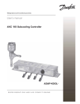
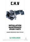
STAGEMAKER
CONTROLLERS
MOTOR1
MOTOR2
MOTOR3
MOTOR4
MOTOR2
MOTOR1
0
0
VERLINDE
MOTOR3
MOTOR4
0
0
START
MARCHE
M O TO R 1
ST A R T
0
M O TO R 1
0
MOTO R 1
0
MO T O R 1
0
MARCHE
VE R L IN D E
INSTALLATION
MAINTENANCE
CONTROLLERS SERIES B – SC -R & FL
FOR STAGEMAKER SM
Version “A” direct control
Version “B” low voltage control
ENGLISH
Version “D” low voltage control BGV-C1
VERLINDE se réserve le droit de modifier ou changer les informations ci-dessus sans préavis
07.2004 – VESEGBSMC1A1
STAGEMAKER CONTROLLERS
Herewith we,
VERLINDE S.A., 2 bd de l'Industrie, BP 59,
F-28501 VERNOUILLET Cedex, Frankrijk
Declare that the product
STAGEMAKER CONTROLLER
Configuration:
BGV-C1
B2 PRMLV-C1
Type:
Date:
12 - 2003
This equipment is to be used in corporation with other machines. It cannot be put into operation until the
systems of which it is a part, has been declared as conforming to the provisions of the directive:
Machines 89/392 EEG, 91/368 EEG, 93/44 EEG, 93/68 EEG
Electric machines 73/23 EEG,
Electromagnetic compatibility 89/336 EEG, 91/263 EEG, 92/31EEG, 93/68 EEG
As well as harmonised norms, in particular EN292, chapter 1 and 2 (safety of machines),
Applied technical standards and specifications, in particular:
IEC 34-1 "Rotating electrical machines”
IEC 34-5 ""Rotating electrical machines”
IEC 947-5-1 "Low voltage switchgear and control gear”
IEC 364 "Electrical installations of buildings”
EN 60204 “Safety of Machines”
Din 56925 (BGV-C1)
The party carrying out the integration will state these passages in declaration of conformity of the machines, the
party will add the regulations and standards to the final installation “machine” and has to comply with, the party
carrying out the integration will draw up the corresponding technical file.
VERLINDE S.A.,
VERNOUILLET, 10-14 -2003
2004.07GB
1
STAGEMAKER CONTROLLERS
CONTENT
chapter
description
page
1
Introduction
4
2
What to do - What not to do
6
3
Guarantee
8
4
Identification
9
5
Functional description
11
6
Cable selection table
17
7
Cable connection tables
18
8
Trouble shooting
19
9
Specifications
20
2004.07GB
2
STAGEMAKER CONTROLLERS
1
INTRODUCTION:
The STAGEMAKER® CONTROLLER has been developed specifically for the control of VERLINDE
STAGEMAKER® chain hoists (motors) series SM5 and SM10. The controllers are available with 4 – 8 or
12 channels and built into a compact suitcase, 19” rack casing, or vertical flightcase.
The STAGEMAKER® CONTROLLER allows you to control the chain hoists individually or simultaneously
with one single button. Pre-selection facilities for all units, PRM models with remote button box incorporate
red and green LED indicators, which indicate the selected hoisting direction. Even STAGEMAKER® hoists
equipped with optional features, such as low voltage circuitry, adjustable limit switches and thermal motor
protection can be controlled with this controller still using only the power cable.
For larger applications, STAGEMAKER® CONTROLLERS can be interconnected to serve a system of
more controlers. All pre-selected motors are activated simultaneously through one single RUN button, as a
standard. Other interconnections are available on request.
STAGEMAKER® CONTROLLERS fully meet the latest European electrical standards (IEC-EMC) and
have been approved by the official APAVE institute. They offer a maximum flexibility, durability and safety.
There are three series of controllers: version A: Economical units with direct selection with or without remote
version B: Contactor controlled units with or without remote. And version D for hoists that comply to BGVC1 (former VBG-70).
Controllers with remote (PRM models) have LED indicators next to the toggle switches on the handheld
box. The connection cable length is 10m.
Version A controllers for direct controlled hoist without remote:
• Combination of power switching and low voltage control in one housing
• Main contactor
• Mushroom emergency button with mechanical interlock
• Individual up/down selectors per motor
• Short circuit protection in main circuit by means of automatic fuses
• Phase reverse facility on incoming CE socket
• Facility to connect a second controller (master-slave function)
• LED indicators for incoming phases
• In- and outputs on CE on models SC and multi connectors on other models
• Single cable connections between controller and hoists
• Thermal protection per group of 4 hoists (except models SC)
Version A controllers for direct controlled hoist with remote have in addition:
• Remote control by means of toggle switches on a control box with flexible cable and multi connector
• All functions with LED indicators allows safe operation, even in the dark
• Manual On/Off & phase reverse switch
2004.07GB
3
STAGEMAKER CONTROLLERS
Version B controllers for low voltage controlled hoist without remote:
• Combination of power switching and contactor control in one housing
• Main contactor
• Mushroom emergency button with mechanical interlock
• Individual set of contactors per motor
• Short circuit protection in main- and control circuit by means of automatic fuses
• Phase reverse facility on incoming CE socket
• Output through CE connectors (one red and one yellow per channel)
• Twin cable connections between controller and hoists (multy connector on request)
• LED indicators for incoming phases
• Thermal protection per group of 4 hoists
• Individual up/down selectors per motor
• Facility to connect a second controller (master-slave function)
Version B controllers for low voltage controlled hoist with remote have in addition:
• Remote control by means of toggle switches on a control box with flexible cable and multi connector
• All functions with LED indicators allows safe operation, even in the dark
• Manual On/Off & phase reverse switch
Version D controllers for low voltage controlled BGV-C1 hoist with remote:
• Combination of power switching and contactor control in one housing
• Main contactor
• Mushroom emergency button with mechanical interlock
• Individual set of contactors per motor
• Short circuit protection in main- and control circuit by means of automatic fuses
• Phase reverse facility on incoming CE socket
• Output through Harting 16p one per channel
• Single multi cable connections between controller and hoists
• LED indicators for incoming phases
• Thermal protection per group of 4 hoists
• Individual up/down selectors per motor
• Remote control by means of toggle switches on a control box with flexible cable and multi connector
• All functions with LED indicators allows safe operation, even in the dark
• Overload indicator
2004.07GB
4
STAGEMAKER CONTROLLERS
2
WHAT TO DO
•
•
•
Mount the controller in a protective casing, (if standard casing is not supplied).
Handle the controller by its grips at the front or at side.
Store the controller in its normal operating position away from aggressive atmospheres (dust,
•
•
•
•
•
Make sure that the controller is always clean and protected from corrosion.
A technician should install the controller with the necessary competence.
Make sure that connecting cables are in good condition and connectors are fitted properly.
Make sure that connecting cables are always symmetrical fitted
If one hoist direction doesn’t match with the Up / Down indicators on the controller, check intermediary
cabling and change two phases.
If all hoists do not match with the indicators, change phases by means of phase reverse facility in the CE
plug or with the reverse switch.
Use only original parts in case of replacements.
Always be ready during the operation to press the emergency stop button. This makes all functions
inactive.
Before operation, check that the load is correctly fastened and installed on the hook. The hook safety
catches should be closed correctly.
Make sure that the load is correctly balanced before moving it.
Make sure that each hoist is vertical to the load and hanging free on its load chain, before starting a
simultaneous operation.
If used out door, use sufficient protection against bad weather conditions.
Use the material under normal working conditions (ambient temperature, atmosphere...).
Moving a single load or truss system, requires experienced operators.
All the necessary precautions should be taken to ensure a correct the distribution of the load and to
avoid overloading a single hoist in set of multiple use. The hoists should be carefully checked individually
before such an operation.
Notify the responsible and competent person after a dangerous operation or if the hoist seems
problematic
•
•
•
•
•
•
•
•
•
•
•
humidity...).
(Abnormal noise, abnormal behaviour...).
Material used outdoors should be protected as well
as possible against bad weather conditions.
2004.07GB
5
WHAT NOT TO DO
•
•
•
•
•
•
•
•
•
•
•
•
•
•
•
•
•
•
•
•
•
•
•
•
Never connect a STAGEMAKER controller to a power source other than specified on the unit.
Do not set down the controller without having an adapted support, to avoid damaging the components on
the rear
Never modify the controller unless the constructor has studied and authorised the modification.
Never modify the values and adjustments of the safety components, outside the limits provided for in the
manual, or without the approval of the constructor.
Never try to repair or intervene on the controller without the authorisation of the constructor or a qualified
electrician.
Do not let an unqualified person use the controller.
Never connect more hoists than the available number of outlets (channels) or number of selector switches
available.
Do not use additional splitters to connect more than one hoist per channel.
Avoid shocks or accidental collision with other objects.
Never open the controller as long as the system is under power.
Never block, or lock the RUN button in order to continue a movement without manual interference.
Do not operate the controller if your physical condition does not allow it.
Never use the controller if it is in bad condition.
Never use suspected spare parts or parts whose origin is not known.
Do not subject the controller to brutal shocks.
Never distract the operator’s attention while he is being operating the system.
Do not use the controller for a purpose or in an area for which it is not intended.
Do not expose the controller to an aggressive atmosphere (temperature, acidity... )
Do not use the safety components as operation components (emergency button, main fuse switch. etc..)
Do not use the controls needlessly (avoid inching - stop-start operation of the buttons). This can cause
overheating and even damage to the hoist.
Do not change the hoisting direction whilst the RUIN button is pressed (hoist under power)
If hoist direction doesn’t match with the indications on the controller, don’t change phases inside the
controller but exchange two phases on the hoist motor or the interconnecting cables.
Never use hoists who are running in the opposite direction of the selected motion.
Do not connect the controller to an unknown power supply, check if power source matches the specification
of the controller and the hoists. (under voltage or over voltage +/- 5%, absence of phase etc...).
2004.07 GB
STAGEMAKER CONTROLLERS
3
GUARANTEE
Our STAGEMAKER controllers are guaranteed for
one year from the date of delivery.
If for a reason outside the control of the vendor, the
delivery is delayed, the time lag cannot exceed three
months.
If the use (installation) of the controller is delayed, the
corresponding extension of the guarantee (a single
extension limited to three months) must be requested,
and written confirmation obtained.
The vendor undertakes to eliminate all operating errors
originating from the concept, the execution, the
components or the materials themselves.
The guarantee does not cover normal wear, or the
failures resulting from abnormal use. It does not cover
damage due to a lack of supervision, to false
operation or to a bad utilisation of the controller,
particularly due to overload, inching, under voltage or
over voltage or connecting errors.
The guarantee does not apply when there is
disassembly, modification or replacement of parts
(mechanical or electrical) by an unauthorised party or
without our prior agreement.
The guarantee only applies for original, factory-installed
spare parts.
For the duration of the guarantee, the vendor
undertakes to replace or repair, free of charge, the
parts, in his workshop, that are acknowledged to be
damaged following examination by a qualified and
authorised technical service.
The guarantee excludes any other services or
indemnities. The repairs covered by the guarantee are
carried out, as a rule, in the workshops of the vendor
or authorised agent. When servicing of the equipment
is done outside these workshops, the labour costs for
disassembly or assembly of these parts are borne by the
vendor when these are done exclusively by his staff or
by an authorised agent. The replaced parts become the
property of the vendor and must be returned to the
vendor at his expense.
For components of a relative particular importance that
are not manufactured by the vendor and which carry
the brand name of specialised manufacturers, the
manufacturer’s guarantee (which can vary according to
the manufacturer) is applicable.
* The guarantee does not apply for expendable parts
defined by the manufacturer:
Fuses
Contactor contacts
2004.07 GB
6
STAGEMAKER CONTROLLERS
4
IDENTIFICATION:
Type codes
Type
SC4P
SC8P
R4P
R8P
R12P
R4PRM
R8PRM
R12PRM
R4PRMR
R8PRMR
R12PRMR
R4PRMRS
R8PRMRS
R12PRMRS
FL4PLV
FL8PLV
FL12PLV
FL8PRMLV
FL12PRMLV
R8CPU-C1
R4PRMLV-C1
R8PRMLV-C1
R12PRMLV-C1
B2PRMLV-C1
B4PRMLV-C1
B8PRMLV-C1
B12PRMLV-C1
Number of
channels
4
8
4
8
12
4
8
12
4
8
12
4
8
12
4
8
12
8
12
8
4
8
12
2
4
8
12
Control
Direct
Direct
Direct
Direct
Direct
Direct
Direct
Direct
Solid state
Solid state
Solid state
Solid state
Solid state
Solid state
Low voltage (48Vac)
Low voltage (48Vac)
Low voltage (48Vac)
Low voltage (48Vac)
Low voltage (48Vac)
Low voltage (48Vac)
Low voltage (48Vac)
Low voltage (48Vac)
Low voltage (48Vac)
Low voltage (48Vac)
Low voltage (48Vac)
Low voltage (48Vac)
Low voltage (48Vac)
Remote
Yes/No
No
No
No
No
No
Yes
Yes
Yes
Option
Option
Option
Yes-radio
Yes-radio
Yes-radio
No
No
No
Yes
Yes
No
Yes
Yes
Yes
Yes
Yes
Yes
Yes
Housing
ABS Hand case
ABS Hand case
19" 3U rack in flight case
19" 3U rack in flight case
19" 6U rack in flight case
19" 3U rack in flight case
19" 3U rack in flight case
19" 6U rack in flight case
19" 3U rack in flight case
19" 3U rack in flight case
19" 6U rack in flight case
19" 3U rack in flight case
19" 3U rack in flight case
19" 6U rack in flight case
Vertical flight case
Vertical flight case
Vertical flight case
Vertical flight case
Vertical flight case
19" 6U rack
19" 6U rack in flight case
19" 6U rack in flight case
19" 9U rack in flight case
Wall mounted cubical
Wall mounted cubical
Wall mounted cubical
Wall mounted cubical
For hoist
configuration
A
A
A
A
A
A
A
A
A
A
A
A
A
A
B1 – B2
B1 – B2
B1 – B2
B1 – B2
B1 – B2
C&D
D
D
D
D
D
D
D
Hoist
connection
CEE plug 4p
CEE plug 4p
Harting 16p
Harting 16p
Harting 16p
Harting 16p
Harting 16p
Harting 16p
Harting 16p
Harting 16p
Harting 16p
Harting 16p
Harting 16p
Harting 16p
2 x CEE plug 4p
2 x CEE plug 4p
2 x CEE plug 4p
2 x CEE plug 4p
2 x CEE plug 4p
Harting 16p
Harting 16p
Harting 16p
Harting 16p
Harting 16p
Harting 16p
Harting 16p
Harting 16p
Note: on request the version B controllers (low voltage) could be supplied with a Harting 6 pole output
per channel for combined power and control, rather than separate CEE connectors for power and control.
2004.07 GB
7
STAGEMAKER CONTROLLERS
Location of controls and connections
Subscription
Main switch
Power indicators
Emergence stop with mechanical interlock
Up / Down selector switches
Plug for interconnection with second unit
Green RUN button
Main & secondary fuses
Thermal protection per group of four
Auxiliary output 16Amp CE-4 pole, not switched
Main power entry 16 amp CE-5p & 0.5 m cable
Main power entry 32 amp CE-5p & 0.5 m cable
Multi connectors for chain hoists output
CE plug for hoist output
Multi connector for remote button box PRM models
2004.07 GB
Position
SC models
R models
Front
n.a.
Front
rear
Front
front
Front
front
Front
rear
Front
front
Front
front
n.a.
front
n.a.
n.a.
Front; SC4P
rear; R4..
Front; SC8P rear; R8..R12..
n.a.
rear
Front
n.a.
n.a.
rear
FL models
Front
Front
Front
Front
Front
Front
Front
Front
Front
n.a.
Front
Front
Front
Front
8
STAGEMAKER CONTROLLERS
5
FUNCTIONAL DESCRIPTION
Cable connections:
• Connect an external power source with the main CE power plug. Be sure that the nature of this source
corresponds to the supplied equipment, such as mentioned aside of the plug.
• Connect the chain hoists through single cables, splitters and/or multi cables with the controller’s outlets.
Note: Controllers SC4P and SC8P, have individual CE outlets, each to support one chain hoist,
controllers FL..PLV have two CE connectors per channel (one for power and one for controls) or
optional a 6 pin multi connector for combined power and control. All other models have 16p multi
connector outlets, each to support 4 hoists. BGV-C1 controllers have a single 16p multi cable
connection per hoist.
Warning:
Use only cables and connectors who are in good condition, inferior connections might cause
severe damage of the equipment and electric motors.
Connecting more than one SM10 or two SM5 hoists per channel might cause severe
damage of the equipment.
Operation:
• Set the main switch to AV (on controllers with remote only)
• Use the selector switches to set the hoists in the upper or lower mode.
• Release the emergency switch by turning anti-clockwise.
• Push the RUN button to activate the pre-selected hoists.
• Check if the hoist direction matches the selected mode. If not reverse, phases on the incoming power or
by means of the main switch if setting to AR (on controllers with remote only).
Note: a) Phase sequence could also be reversed by means of changing two phase-pins fitted on a satellite
inside the 32Amp CE connector. Push and turn the satellite with a screwdriver 180 degrees.
b) There are three pre-selection modes; upper, lower or zero modes. Only pre-selected hoists in
upper or lower mode will come in to the corresponding operation.
c) Don’t change the hoist direction whilst motors are under power. Release first the RUN button,
make your changes and push the RUN button again.
•
•
If circumstances require doing so, push the RED button in order to stop all hoists immediately.
Release this button by turning it anti clockwise.
Note: a) Version D controllers (BGV-C1) do have an indicator for overload. If this signal is activated,
a reset needs to made by pushing and re-leasing the RED E-stop button.
b) BGV-C1 hoist do have emergency limit switches. If for some reason these are activated, the
main contactor will disconnect the power to the hoist and intervention on the hoist is required.
2004.07 GB
9
STAGEMAKER CONTROLLERS
Master slave function: (not available on version D controllers)
A set-up of 2x4 or 2x8 or more hoist could be controlled simultaneous from one position, using two or more
STAGEMAKER® controllers,
Warning: Master slave connections can be made between: SC models and R4P-R8P and R12P
controllers or R8PRM and R12PRM controllers. Controllers with and without remote may not
be mixed, this will cause internal damage. For the interconnection of the controllers are special
cables required. Contact us for information.
.
•
•
•
Interconnect the I/O START plugs of two controllers using a special cable (option)
Set the pre-selector switches of both controllers in the required mode
Push the RUN button of one of the two controllers. This one will be the master the second one the
slave. The emergency button on the master controller is effective on the slave as well.
G EN ER A L
C O N T R OMLO T O R 1 - 4
1. 6
1. 4
1. 2
1. 6
1. 4
1. 2
STOP
MO TO R 1
M O T O R 5-8
OFF
1
0
OF F
MO TO R 2
MO TO R 3
0
MO TO R 4
0
0
1
S TART
T est
STOP
ST ART
Tes t
Telem ecanique
Telem e canique
MO TO R 5
ST A R T
0
MO TO R 6
MO TO R 7
0
MO TO R 8
0
0
VERLINDE
type R8P
L1
Connection cable
L2
L3
FUSE
FUSE
MO TO R 1 - 4
MO TO R 1 - 8
I/O S T A R T
FUSE
3 X 4 0 0 V+ N + T 1 6 A
G EN ER A L
C O N T R OMLO T O R 1 - 4
1. 6
1. 4
1. 2
1. 2
0
OF F
1. 6
1. 4
STOP
MO TO R 1
M O T O R 5-8
OFF
1
MO TO R 2
0
MO TO R 3
0
MO TO R 4
0
1
S TART
STOP
T est
ST ART
Tes t
Telem ecanique
Telem e canique
MO TO R 5
ST A R T
0
MO TO R 6
0
MO TO R 7
0
MO TO R 8
0
VERLINDE
type R8P
2 x Model R8P
L1
L2
L3
FUSE
FUSE
MO TO R 1 - 4
MO TO R 1 - 8
I/O S T A R T
FUSE
3 X 4 0 0 V+ N + T 1 6 A
Special applications:
With the use of a special box (option) connected to the I/O START outlets of more controllers, it is
possible to run up to 40 motors at the same time under one button.
(5 x 4 channel or 8 channel controllers, any type without remote!)
MOTOR1
MOTOR2
MOTOR1
MOTOR2
MOTOR1
MOTOR2
MOTOR1
MOTOR2
MOTOR1
MOTOR2
MOTOR1
MOTOR2
MOTOR1
MOTOR2
MOTOR1
MOTOR2
MOTOR1
MOTOR2
0
0
0
0
0
0
0
0
0
0
VERLINDE
MOTOR3
0
MOTOR3
VERLINDE
MOTOR4
MOTOR4
MOTOR3
0
0
START
MARCHE
MOTOR3
VERLINDE
MOTOR4
MOTOR4
MOTOR3
0
0
START
MARCHE
MOTOR3
VERLINDE
MOTOR4
MOTOR4
MOTOR3
0
0
START
MARCHE
MOTOR3
VERLINDE
MOTOR4
MOTOR4
MOTOR3
0
0
MOTOR2
MOTOR3
MOTOR4
MOTOR4
0
START
MARCHE
MOTOR1
START
MARCHE
5 x Model SC4P
•
•
•
Interconnect the I/O START plugs of all controllers using the connection cable (option)
Set the pre-selector switches of all controllers in the required mode
Push the RUN button of one of the controllers. This one will be the master the others are the slaves.
The emergency button on the master controller is effective on the slaves as well.
2004.07 GB
10
STAGEMAKER CONTROLLERS
R model CONTROLLERS version A
1
HARTING
HARTING
2. Motor cables 10 or 20 M:
code No. 5229263 or 5229264
2
3. Splitter (fan-out) CE
52292667
3
M : code No.
4. Multy cables 10 or 20 M:
code No. 5229261 or 5229262
G EN E R A L
C O N T R OMLO T O R 1 - 4
1. 6
1. 4
1. 2
1. 6
1. 4
1. 2
ST OP
M O TO R 1
M O TO R 5 - 8
OF F
1
0
OF F
M O TO R 2
0
MO TO R 3
0
MO TO R 4
0
1
ST OP
ST ART
Test
ST ART
Tes t
Tele m ecanique
Telem ecanique
M O TO R 5
ST A R T
0
M O TO R 6
0
MO TO R 7
0
MO TO R 8
0
VERLINDE
type R8P
L1
L2
L3
FUSE
FUSE
MO TO R 1 - 4
M O TO R 1 - 8
I/O ST A R T
FUSE
HARTING
3 X4 0 0 V+N +T 1 6 A
R8P rear side
Power
input
Power
input
2004.07 GB
11
STAGEMAKER CONTROLLERS
FL model CONTROLLERS version B
1. Motor cables 10 or 20 M:
code No. 52292663 or 52292664
1
2. Control cables 10 or 20 M:
code No. 5229853 or 5229854
2
MOTOR 1
MOTOR 2
MOTOR 3
MOTOR 4
G EN ER AL
CEE
CEE
CEE
16-6h
3P+PE IP44
16-6h
3P+PE IP44
1 6-6h
3 P+ PE IP44
16-6h
3P+PE IP44
MOTOR 1
MOTOR 2
MOTOR 3
MOTOR 4
M O T OR
1 -4
C ON TR O L
CEE
1 .6
1.4
NORMAL
M O TO R
5 -8
OFF
1.6
1.4
1.6
1. 4
.3.1
1 .2
1
M O TO R
1 3 -1 6
OFF
.3.1
1.2
1
M OT O R
9 -1 2
OFF
.3.1
1 .2
1
PHASE
F AILURE
STOP
START
STOP
Test
INVERSE
Telemecanique
.4
.2
START
STOP
Test
Telemecanique
.4
.2
START
Test
Telemecanique
.4.2
R EM O TE
R EM O TE FE S T
I /O S T A R T
48VA C
I /O
CEE
CEE
CEE
CEE
16-6h
3P+PE IP44
16-6h
3P+PE IP44
1 6-6h
3 P+ PE IP44
16-6h
3P+PE IP44
L IG H T
S T A R TC O N T R O L
FUSE
A R
MOTOR 5
MOTOR 6
MOTOR 7
A V
M O T O R M1 O T O R M2 O T O R M3 O T O R 4
MOTOR 8
M O T O R M5 O T O R M6 O T O R M7 O T O R 8
CEE
CEE
CEE
16-6h
3P+PE IP44
16-6h
3P+PE IP44
1 6-6h
3 P+ PE IP44
16-6h
3P+PE IP44
P G21
CEE
M O T O RM9O T O R M1 0O T O R M1 1O T O R 1 2
VERLINDE
LIFTING EQUIPMENT
MOTOR 5
MOTOR 6
MOTOR 7
MOTOR 8
CEE
CEE
CEE
CEE
16-6h
3P+PE IP44
16-6h
3P+PE IP44
1 6-6h
3 P+ PE IP44
16-6h
3P+PE IP44
FL12PRM LV
M O T O R M1 3O T O R M1 4O T O R M1 5O T O R 1 6
STAR T
MOTOR 1 MOTOR 2 MOTOR 3 MOTOR 4
MOTOR 5 MOTOR 6 MOTOR 7 MOTOR 8
MOTOR 9 MOTOR 10 MOTOR 11 MOTOR 12
START
VERLINDE
LIFTING EQ UIPMENT
Controller FL8PRMLV
Rear side with CE connecotors
Optional Harting 6 pin available for
combined power and control.
(FL8PRMLVH)
PG21
Power input
2004.07 GB
12
STAGEMAKER CONTROLLERS
R model CONTROLLERS version D
HARTING
HARTING
HARTING
HARTING
1. Multy cables 10 or 20 M:
code No. 5229261 or 5229262
1
HARTING
HARTING
Power input
Controller R8PRMLV-C1
2004.07 GB
13
STAGEMAKER CONTROLLERS
B model CONTROLLERS version D
HARTING
HARTING
HARTING
1. Multy cables 10 or 20 M:
code No. 5229261 or 5229262
1
HARTING
HARTING
M O TO R 1
M O TO R 2
PO W ER
SU PPLY
I
3x400V
POWER ON
PHASEN
FAILURE
R EM O TE
O
Power input
PG21
M O T O R
1 /1 + 2 / 2
O N
Controller B2PRMLV-C1
P O W E R
HARTING
I
B2PRMLV-C1
2004.07 GB
14
STAGEMAKER CONTROLLERS
6
CABLE SELECTION TABLE
The table hereunder gives an indication of the maximum length of cables between controller and hoist
(motor). They are calculated in accordance to NE 60 204 and worse case consideration
c
1.5mm² or
400V/50Hz
L max (m)
SM1
SM5
SM10
SM25
230
100
65
40
115
50
d
230V/50Hz
L max (m)
In Max
(A)
1.4
3.2
1.75
7.75
75
40
25
35
20
In Max
(A)
2.5
4.5
7
14
2.5mm² sections
400V/50Hz
L max (m)
SM1
SM5
SM10
SM25
1.5²mm² + 2.5mm² sections
255
110
75
45
125
55
35
230V/50Hz
L max (m)
In Max
(A)
1.4
3.2
1.75
7.75
80
45
25
40
20
In Max
(A)
2.5
4.5
7
14
Limitations
Cable with different section, i.e. 1.5mm² and 2.5mm², can be connected together. But maximum length of
cable depends of the smallest section. That is why if a cable assembling contains both 1.5mm² and 2.5mm²
cable section you should refer to chart c. If the cable assembling contains only 2.5mm² section you should
refer to chart d.
Those chartS have been calculated according to EN-60-204 with a maximum voltage drop of 5%.
2004.07 GB
15
STAGEMAKER CONTROLLERS
7 CABLE CONNECTION DATA
Version A and B single motor cable with
CEE plugs for power
Version B2 single control cable with
CEE plug for control
Wires
L1 / U1
L2 / V1
L3 / W1
PE
Wires
1
2
3
PE
Color
brown
blue
black
yellow/green
Pin n°
1
2
3
PE
Color
Function
brown
48Vac
blue
up
Ï
black
down Ð
yellow/green
Version A and B splitter (fan-in and fanout)
Version A and B multi cable,
extension cable for 4 motors
Wires
L1
L2
L3
GND
L1
L2
L3
GND
L1
L2
L3
GND
L1
L2
L3
GND
Wires
L1
L2
L3
GND
L1
L2
L3
GND
L1
L2
L3
GND
L1
L2
L3
GND
Color
brown
blue
black
yellow/green
brown
blue
black
yellow/green
brown
blue
black
yellow/green
brown
blue
black
yellow/green
Pin n°
1
2
2
4
5
6
7
8
9
10
11
12
13
14
15
16+PE
2004.07 GB
Wire n°
1
2
3
4
5
6
7
8
9
10
11
12
13
14
15
16
Pin n°
1
2
3
PE
Pin n°
1
2
2
4
5
6
7
8
9
10
11
12
13
14
15
16+PE
16
STAGEMAKER CONTROLLERS
Control and motor cable for version D
(BGV-C1) controller B/RxPRMLV-C1
Plug
Hoist
Pin n° Color
Function
Terminal
1
brown
L1
L1
2
blue
L2
L2
3
black
L3
L3
4
white
48Vac
1
5
yellow
A/U
5
6
transparent
7
orange
signal Ï
8
8
pink
action Ï
2
9
purple
“by-pass”
4
10
red
signal Ð
8
11
grey
action Ð
3
12
grey/white
13
brown/white 0Volt
9
14
blue/white
15
red/white
16
black/white
PE
yellow / green Earth
PE
Controllers FL.. single cable with
Harting plugs for power & control
Wires
L1
L2
L3
Common
Motion Up
Motion Down
PE
yellow/green
Pin n°
1
2
3
4
5
6
PE
Note :
These tables should be respected at any
time to avoid damage to the hoists or
controllers !
2004.07 GB
17
STAGEMAKER CONTROLLERS
8
TROUBLE SHOOTING
If your controller doesn’t work,
• the power source
• the main switch (PRM series only)
• the fuses
• thermal protection
• if the emergency button is pressed
• pre-selection switch settings
• output cables
Warning:
9
:
:
:
:
:
:
:
check;
all three lamps should blink
in AV or AR mode
switchbar in upper mode
black button in down mode
turn anticlockwise and pull
up or down mode
connected
Before going in the panel it self, or removing the top plate, first disconnect the main power
entry plug.
SPECIFICATIONS
•
Power supply
:
•
•
•
Controls direct switching models
Controls remote switching models
Maximum switching capacity
:
:
:
2004.07 GB
3 x 400 V – 50 Hz
or 3 x230 V – 50Hz
230 Vac
24 Vac
1.75 kW per channel at 400 V
0.9 kW per channel at 230 V
18