1
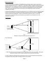
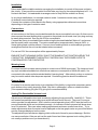
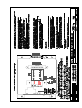
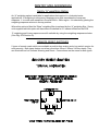
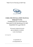
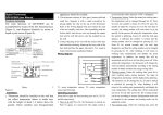
SENTRY
MK2
USERS MANUAL
Sentry MK 2
ENVIRONMENTAL NOISE CONTROL SYSTEM
INSTALLATION INFORMATION
MK2
The Sentry MK2 basically performs the same functions as the original Formula Sound Sentry but
with added features and options.
•
New case design provides easier connections via cable entry knock-outs and screw terminals
•
•
A choice of internal microphone (supplied factory fitted as standard) or external microphone
may be selected
Removable cover provides access to all connectors and settings. Anti-tamper seals are
provided.
Anti-tamper microphone circuitry is incorporated with a front panel indicator.
•
Dual mains voltage operation is standard (internally switchable)
•
General Detail
The Sentry was designed to help solve some of the environmental noise problems encountered at
entertainment venues and in working areas.
The unit was designed to be as versatile in use as possible and features a large bar graph
display. Although its main application is to control mains power outlets in entertainment venues it
is not restricted to this application. Basically any function that can be controlled by a relay or
switch can be controlled by the Sentry. These may include disconnecting loudspeakers, switching
passive attenuators to reduce system volume or acting as the trigger into an active attenuator
system.
The Sentry may also be used as a stand alone display unit indicating sound pressure levels or in
industrial applications to switch on warning lamps or illuminated signs advising the use of ear
defenders when the safe noise level is exceeded.
It is microphone driven and has its own built in microphone.
The Sentry incorporates the facility to operate at two different sound level thresholds which may
be selected manually by a remote key switch or similar, or automatically by a time switch.
(Switches not supplied)
The Sentry is provided with connectors to interface with a range of equipment, plus internally
selectable options to make the system as versatile as possible.
Our technical department is always on hand to advise when unusual applications are
encountered.
Page 1
Operation
The Sentry features a large bar-graph VU meter with 23dB range to give a visual indication of the
noise level in a venue. This has the advantage over other units in that anyone can see the volume
level and can see how their actions are contributing to this level. While the meter is operating in
the green section, with even an occasional peak into the red, there is no cause for concern.
The Sentry will operate within the range 80dB - 120dB and may be pre-set to anywhere in this
range. Provision is included to operate at 2 different levels, for instance at different times of day.
This selection can be performed manually or automatically by a time switch. A front panel
indicator shows when level 2 is selected.
If a mains warning lamp is connected it will operate at the same point as the two red sections of
the meter. These are labelled “WARNING”.
If the noise level is high enough to light the “OVER LIMIT” section of the meter (three red sections)
the noise has exceeded the allowable limit. If this is allowed to continue for more than the set time
period the unit will trip and remove the power to the contactor or relay. Visual indication of this is
provided above the reset button.
When the unit is first powered up the RESET indicator will be lit - wait for a few seconds and
press the re-set button. The Sentry will now be re-set and ready for normal operation.
The action of the timing circuit means that continually exceeding the limit even for short periods
may eventually trip the unit.
The unit has to be manually reset to restore power and this will only be possible after a short time.
The reset time is determined by the amount by which the unit is driven over limit. e.g. tripping the
unit by just exceeding the limit will result in a short period of a few seconds before reset is
possible. Tripping the unit by grossly exceeding the limit will require a longer period before reset
is possible.
NOTE. It is important that a check is made before the unit is re-set.
Check that it is safe to do so.
Audio systems generally need to be powered up in a specific order. In an audio system
comprising of different components amplifiers, mixers, etc. a general rule is to switch power
amplifiers off first and on last to avoid possible loudspeaker damage. Therefore a band or D.J.
may need to turn off amplification equipment to protect loudspeakers before the power is
restored.
Mic Tamper
An anti-tamper circuit is incorporated which if enabled will detect the presence of tape etc. placed
on the case above the internal microphone in an attempt to artificially raise the internally set
threshold. To enable this function adjust the T.S. preset (X) on Drg 879. (turn the pre-set to
approx the 11 o’clock position. External microphones being disconnected will also be detected
by a seperate circuit. A front panel indicator will show MIC TAMPER.
The Sentry will switch off if the Mic tamper or Security loop indicators are illuminated.
All connections and adjustments are located beneath the removable cover plate. None reusable
security labels are supplied with each unit to help ensure that unauthorised tampering is detected.
Timer
The period of time that noise “over limit” is tolerated before the unit trips out is variable over the
range of 10 - 70 seconds. A pre-set is provided to adjust this should it be necessary - the factory
setting is approx. 20 seconds.
Page 2
Mounting Position
The Sentry should be mounted on a flat solid surface preferably where it can be seen by the
persons affected by its use (D.J., band, etc.). It should be located in a position where it cannot be
tampered with, e.g. a minimum of 8 feet (2.5 meters) from the floor, ideally on a wall facing the
noise source. It is not necessary to have a microphone suspended above the band or dance
floor. If the Sentry can hear the noise source above the background noise the unit can be
calibrated accordingly.
Avoid positions that are too close to the noise source e.g. in a typical concert room with the stage
area at one end the Sentry should be positioned centrally away from the stage at a minimum
distance equal to the stage width. If there is more than one source of noise, e.g. several
instruments in a band the Sentry should ideally be at a position equal distance from each
instrument. (see Fig1)
Ideal Position
w
“A”
Sentry
x
1234
1234
1234
1234
1234
1234
1234
1234
1234
1234
1234
123
123
123
123
123
123
123
123
123
123
123
123
123
123
123
123
“W”
Stage
At least 2.5m
From Floor level
y
z
123
123
123
123
123
123
123
123
123
123
123
123
123
123
123
123
Fig 1
Distance “A” should never be less than distance “W”.
Poor Positioning
w
x
Position (B)
123
Sentry
123
123
123
123
123
123
123
Better position
Sentry
123
123
123
123
123
123
123
123
y
z
Poor position
123
123
123
123
123
123
123
123
123
123
123
123
123
123
123
123
123
123
123
123
123
123
123
123
Stage
123
123
123
123
123
123
123
123
Fig 2
In Fig 2 the instruments y&z will appear louder to the Sentry than instruments w&x. Moving the
Sentry back away from the stage to position (B) will minimise the problem
In order to help solve difficult location problems provision is now included to connect a remote
microphone to the Sentry MK2. See Drg No 879 for more details.
Page 3
Cable Entry And Fixing
Read this section fully before proceeding
Customising the box. Cable entry knock outs are provided on the rear and bottom faces of the
unit, using the rear cable entrys can result in a very neat installation. Select the cable entry
positions to be used and remove the appropriate knock outs. (A small flat blade screwdriver on
the perimeter of the hole will assist prizing out the blanking plugs.) Remove any sharp edges that
may damage cables or use protective grommets (not supplied)
NOTE:- Use a separate cable entry for mains connections. Always keep low voltage cables
away from mains cables and connections
Fastening the unit. The unit is secured to a wall by 3 screws (not supplied). The top centre
screw locates in a key hole slot on the back of the unit.
Use No. 10 or 12 screws with round heads 1.5" (38mm) minimum length. Brick or masonry walls
will require drilling and plugging in the usual manner.
First remove the cover to expose the bottom mounting screw holes, these are located in the
bottom corners of the case. Fit the top centre screw 30 mm down from the required top case
position, leave this screw approx. 1.5mm proud of the mounting face.
The unit may now be suspended on this screw while the two bottom mounting screw positions are
marked out (ensure that the unit is captive on the screw head so it cannot fall). Fit the bottom two
mounting screws.
Check that the unit is secure, cannot fall, and is not loose on the screws.
In high risk areas security screws should be utilised to prevent the unit from being removed.
Wiring For Applications Controlling The Mains Power.
All mains wiring must be installed in accordance with IEE Regulations. If after reading
these instructions you are not sure how to proceed you should seek help from a
qualified electrician.
Overview
The Sentry provides outputs to control a contactor or relay which in turn will control the mains
supply. This strategy allows the Sentry to be mounted in the most suitable position for noise
measuring whilst the mains switching equipment (the relay or contactor) can be mounted in the
most convenient position for switching the mains power (fuse cupboard, etc.)
(A 32amp fully fused boxed contactor with low voltage interface has been designed for use with
the Sentry and is available from Formula Sound Ltd)
The extra safety and possible lower installation costs stemming from the fact that only low voltage
cable is required between the Sentry and contactor at minimal current are added benefits.
The Sentry also provides connections to use a mains coil contactor with a maximum coil
consumption of 60VA.
Page 4
Installation
Select and install a suitable contactor, arranging the installation to control all the power outlets in
the vicinity. (If any are left uncontrolled it will not take very long for the enterprising band or D. J. to
find and use them. It is inadvisable to arrange control of only half the outlets in a venue).
In very large installations, it is a simple matter to make 1 contactor control many others
of whatever current rating is required.
Connect the contactor control back to the Sentry using appropriate cable and connections
depending on the type of contactor used.
Connections
All connections to the Sentry are located beneath the lower removable front cover. On this cover is
also mounted the reset button which connects to the printed circuit board via a 2 pin plug and may
be easily disconnected. See Drg No 879.for more details.
Connect the Sentry to a suitable mains outlet using the terminals labelled “Mains In” and ensure
that the earth is also connected. The mains consumption is approximately 1amp at 240V - a
5amp lighting feed could be utilised. Connect via an isolating switch or removable plug socket
arrangement so that the unit can be isolated when necessary.
For use on 120V the consumption will be approximately 2amps
ENSURE THAT THE MAINS SUPPLY IS NOT THE SAME AS THAT CONTROLLED BY THE
CONTACTOR. REMEMBER THIS SUPPLY CONTROLS ALL THE POWER OUTLETS
CONTROLLED BY THE CONTACTOR.
Warning Lamp
Provision to switch a mains warning lamp to a maximum of 60VA is provided. The lamp can be of
any style considered suitable but must have a maximum consumption of 60VA (60 watts). It is
connected to the mains outlet terminals labelled “warning lamp”. Alternatively a relay or contactor
may be used to switch other lamps as required. Good wiring practice should be observed.
Remote Reset
Provision for a remote reset button is provided and if this facility is required a momentary action
push button or key switch should be fitted. Site this in a Manager’s office or suitable location.
(See separate drawing (Drg No 879) giving full connection details).
Setting The Permissible Volume Level
Adjustment of allowable noise level is made by adjusting the pre-sets ADJ 1 and ADJ 2. These
are located beneath the removable cover at the left hand end of the unit. They are 10-turn presets to provide fine adjustment. ADJ1 sets the normal operating level, ADJ 2 sets the level for a
second threshold which can be initiated remotely. An indicator on the front panel will show when
level 2 is selected. Take care when making adjustments and use a small screw driver . Try to
make adjustments when the noise level is displayed on the bar graph meter as you will be able to
see the changes displayed on the meter.
The adjustment pre-sets have a slipping clutch at the end of travel to prevent damage. But this
can cause confusion if the pre-set is at the end of travel as it then appears to do nothing (this is
not usually a problem once you know about it).
Page 5
Setting The Permissible Volume Level continued
The actual sound pressure level (SPL) at which the unit operates can only be determined by
measuring the noise level using a calibrated sound pressure level meter and adjusting the unit
accordingly.
Alternatively the unit may be adjusted using trial and error but this should be used only as a
temporary measure or last resort. Measuring the sound level and setting to a limit agreed with the
local area official is the only recommended method.
An internal measuring microphone is fitted which will be suitable for most applications but should
the need arise an external microphone can be connected. The external microphone may be a
moving coil type, capacitor or electret. Microphone phantom power is provided and may be
selected as required. Select a microphone with the required frequency response and polar
response. (Please telephone our technical department if help is required).
NOTES:- If the unit is to be used in an entertainment venue to control a band or disco use a meter
with either a linear scale or ‘C’ weighting response.
The frequency response of the measuring circuit of the Sentry may be selected to be, Linear (Flat
response), ‘C’ (Conventional “C” scale) or Bass (LP filter @300Hz 12dB per octave slope.)
See Drg No 879
‘A’ weighting is a frequency response curve that resembles the human ear response. It is much
more sensitive in the mid 500Hz - 5kHz region. It is not recommended for entertainment venues
as it is less sensitive to the bass regions where most problems lie. An “A” weighting filter may be
fitted as a factory option if required.
SECURITY LABELS ARE PROVIDED. THESE SHOULD BE FITTED TO
COVER THE SCREW HEADS HOLDING THE REMOVABLE COVER IN
PLACE AND WILL REVEAL ANY UNAUTHORISED ATTEMPT TO CHANGE
THE THRESHOLDS
ALWAYS FIT SECURITY LABELS AFTER ADJUSTMENTS HAVE BEEN MADE.
EXTRA LABELS ARE AVAILABLE FROM FORMULA SOUND IF REQUIRED.
Remember that the acoustic characteristics of a venue will change depending on the number of
people in it. Our experience has shown that it is always advisable to take readings when the
venue is in use. It would be a wise precaution to allow in your costings for a site visit during
opening hours to take measurements and make final adjustments.
Security Loop
Provision to connect a security loop is provided. This may be required to detect open doors or
windows that would impair the sound proofing of a building, etc. Magnetically operated reed
switches of the type used in intruder alarms are most convenient for this application. If this facility
is not required a wire link must be connected to allow the Sentry to work normally. (see Drg No
879)
A front panel indicator shows if the security loop is opened.
Tampering
Correctly locating the unit out of reach is the best form of security.
If you find that you have problems with unauthorised persons tampering with the settings, security
screws are available to replace the cover screws, a special key is also supplied for the fitting
and removal of these screws. Contact FORMULA SOUND sales office for more details
Page 6
Internal Settings
Several optional settings are available internally. These are all shown on a separate drawing
Drg No 879
Internal External Microphone Selection
This is accomplished by the position of two jumper plugs on pin headers. Take care to move both
jumpers and ensure that they connect correctly. The positions are shown on the P.C.B.
External Microphone Phantom power
Phantom power is available for capacitor and electret microphones, two jumper plugs select in a
similar manner to microphone selection. Ensure both jumpers are moved and connected
correctly.
Weighting Selection
The position of one jumper plug selects the response on the measuring microphone. The
positions are shown on the P.C.B. Ensure that the jumper is seated correctly.
Special weighting options are possible - contact Formula Sound for further details.
External Microphone connection
A 3 way terminal strip is provided for the connection of a remote microphone. The microphone
should be low impedance and balanced and good quality twin screened cable should be used for
the connections. Select a microphone with the desired frequency response and directional
characteristics.
Led Indicators
Outputs are provided for remote led indicators:- MIC TAMPER, LEVEL 2, WARNING, RESET
REQUIRED. If more than two leds are to be connected they share a common terminal. Led
current limiting resistors are not required. Leds may be connected directly. These outputs are
also sufficient to drive a contactor with low voltage interface if required.
Timer Adjustment
The period of time that noise “over limit” is tolerated before the unit trips out is variable over the
range of 10 - 70 seconds. If adjustment is required locate the timer pre-set from Drg No 879 and
adjust with a small terminal screwdriver as required. Due to the action of the circuit you may have
to wait up to 70 seconds for the timing capacitor to discharge before new timer settings will take
place.
FORMULA SOUND LTD.
STUART ROAD
ASHTON ROAD
BREDBURY
STOCKPORT
CHESHIRE
SK6 2SR
TEL: 44 (0)161 494 5650
FAX: 44 (0)161 494 5651
Email [email protected]
www.formula-sound.com
Page 7
SENTRY MK2 ADDENDUM
Sentry “A” weighting Option
An “A” weighting option is available for applications that require it i.e. Industrial noise
applications. ‘A’ weighting is a frequency response curve that resembles the human ear
response. It is much more sensitive in the mid 500Hz - 5kHz region. It is selected by placing the
weighting response selector in the top position.
Where this option is fitted the “Bass” weighting filter is replaced by the “A” weighting filter. Sentry
units supplied with this option will have been re-labelled as “A” instead of Bass on the PCB.
‘C’ weighting and Linear response are still available by using the weighting response selector.
(See Drg. 879 Section D).
REMOTE RESET SWITCHES
2 types of remote reset switch are available a push button version and a key switch version for
extra security. Both types feature a surface mount box 65mm X 65mm X 45mm depth. They
are fitted with led’s to indicate Warning and Reset. Connections are the same for both types.