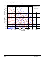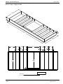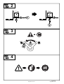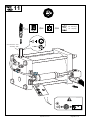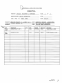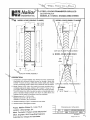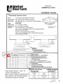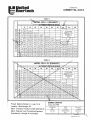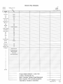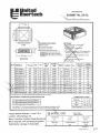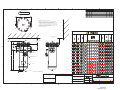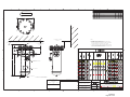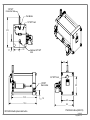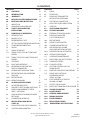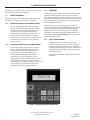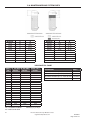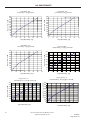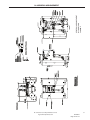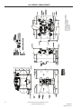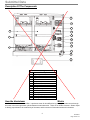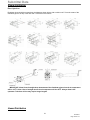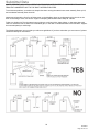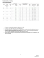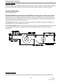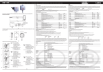
1
Paulson-Cheek Mechanical 6145 Northbelt Parkway Suite F Norcross, GA 30071 Ga. Reg. 000386 770. 729. 0076 770. 729. 1076 Fax Medline Wildcat II – Lines 7&8 Lithia Springs, GA HVAC Submittal June 18, 2015 General Contractor: Alston Construction Mechanical Engineer: Paulson-Cheek Mechaical, Inc. Mechanical Contractor: Paulson-Cheek Mechanical, Inc. Section 1 Rooftop Units Section 2 Air Compressors Section 3 Grilles, Registers, & Diffusers Section 4 Gravity Ventilator Hoods with Motorized Dampers Section 5 Roof Exhaust Fan Section 6 Roof Curbs Section 7 Drop Box Diffuser Section 8 Wall Intake Louvers Section 9 Gas-Fired Unit Heater Section 10 Desiccant Dryers Section 11 Humidifiers 6/18/2015 Page 1 of 174 HVAC Submittal Cover Sheet SECTION: 1 PRODUCT: Rooftop Units Paulson-Cheek Mechanical, Inc. 6145 Norhtbelt Parkway, Suite F Norcross, GA 30071 PROJECT: Medline Wildcat II - Lines 7&8 PHONE: 770-729-0076 FAX: 770-729-1076 LOCATION: Lithia Springs, GA Paulson-Cheek Mechanical, Inc. ARCHITECT'S/ENGINEER'S STAMP Paulson-Cheek Mechanical, Inc. DATE RECEIVED: MANUFACTURER: SUPPLIER: SUBMITTED DATE: X 05/21/15 Trane Trane 05/21/15 NO ERRORS DETECTED CORRECT EXCEPTIONS NOTED THIS APPROVAL OF SHOP DRAWINGS DOES NOT RELIEVE THE SUBCONTRACTOR OR VENDOR FROM THE REQUIREMENTS OF THE CONTRACT DOCUMENTS. CHECKED BY: DATE CHECKED: Carden Clark 05/21/15 6/18/2015 Page 2 of 174 REVISED Submittal Prepared For: Paulson Cheek Mechanical Attn: Danny Brooks 6145 Northbelt Parkway Norcross, GA 30071 Sold To: Paulson Cheek Mechanical Date: May 05, 2015 Job Name: Medline - Area II Production Line Trane U.S. Inc. is pleased to provide the enclosed submittal for your review and approval. Product Summary Qty Product 6 Packaged Rooftop, Cooling / Heating Units Notes: 1. Fire/smoke devices, external isolation, spare filters/belts are not included by Trane. Sincerely, The attached information describes the equipment we propose to furnish for this project, and is submitted for your approval. Becky Warner Sanborn, LEED AP Account Manager Trane U.S. Inc. - Ingersoll Rand Office: 678-775-4202 Cell: 404-226-6954 Email: [email protected] www.trane.com J:\JOBS\38\222216\4\Medline - Area II Production Line Revised High Heat 5-5-2015.doc 6/18/2015 Page 3 of 174 Table Of Contents Product Summary .......................................................................................................................... 1 Packaged Rooftop, Cooling / Heating Units (Items A1, A2) ...................................................... 3 Tag Data ................................................................................................................................................... 3 Product Data ............................................................................................................................................ 3 Performance Data .................................................................................................................................... 4 Mechanical Specifications ........................................................................................................................ 5 Unit Dimensions ....................................................................................................................................... 7 Fan Curve ............................................................................................................................................... 13 Weight, Clearance & Rigging Diagram ................................................................................................... 15 Accessory ............................................................................................................................................... 17 Field Wiring ............................................................................................................................................ 21 Field Installed Options - Part/Order Number Summary ........................................................... 22 Packaged Rooftop, Cooling / Heating Units ........................................................................................... 22 6/18/2015 Page 4 of 174 Medline - Area II Production Line May 05, 2015 Tag Data - Packaged Rooftop, Cooling / Heating Units (Qty: 6) Model Number Item Tag(s) Qty Description A1 50 TON 5 50 Ton Voy III YCD600B4H-1B4ND2-BC-E---0K0-00R-0-------XA--* A2 30 TON 1 30 Ton Voy III YCD360B4L-1B1CD2-BC-E---0K0-00R-0-------XA--* Product Data - Packaged Rooftop, Cooling / Heating Units All Units Dx Cooling with Natural Gas Heat Downflow Supply and Upflow Return 460 Volt 60 Hertz 3 Phase Barometric Relief 2" MERV 8 High Efficiency, Throwaway Filter 0-100% Economizer, Reference Enthalpy Control Constant Volume - discharge temp control Thru-The-Base Electrical Provision Non-Fused Disconnect Switch Field Powered Ground Fault Convenience Outlet Lontalk communication interface Standard efficiency unit Clogged filter switch Flat Roof Curb (Fld) Room sensor with temperature adjustment and override (Fld) 5 year Compressor Parts Warranty Start Up by Trane Service Team 1 Year Labor Warranty Whole Unit by Trane Service Team Item: A1 Qty: 5 Tag(s): 50 TON 50 ton 60 Hertz High Heat 20 Hp Supply Motor 725/604 (60/50 hz) Supply Fan Drive Item: A2 Qty: 1 Tag(s): 30 TON 30 ton 60 Hertz Low Heat 7.5 Hp Supply Motor 650/541 (60/50 hz) Supply Fan Drive FLD = Furnished by Trane U.S. Inc. / Installed by Others Equipment Submittal Page 3 of 22 6/18/2015 Page 5 of 174 Medline - Area II Production Line May 05, 2015 Performance Data - Packaged Rooftop, Cooling / Heating Units Tags 50 TON 30 TON Leaving coil DB (F) 60.69 59.34 Leaving coil WB (F) 59.67 57.78 Design airflow (cfm) 20000 12000 Cooling EDB (F) 83.50 80.00 Cooling EWB (F) 69.00 67.00 Ambient temp (F) 95.00 95.00 Ent air relative humidity (%) 48.32 51.08 Cooling LDB (F) 63.44 61.33 Cooling LWB (F) 60.67 58.53 Gross total capacity (MBh) 606.53 348.52 Gross sensible capacity (MBh) 494.06 270.84 Gross latent capacity (MBh) 112.48 77.68 Net total capacity (MBh) 555.77 326.56 Net sensible capacity (MBh) 443.30 248.88 Net sensible heat ratio (%) 79.76 76.21 Input htg capacity (MBh) 800.00 350.00 Output htg capacity (MBh) 648.00 283.00 Heating EAT (F) 70.00 70.00 Heating LAT (F) 100.30 92.20 Heating delta T (F) 30.30 22.20 ESP (in H2O) 1.000 1.000 Actual Supply Motor BHP (hp) 18.333 7.414 Supply Motor Power (kW) (rpm) 707 654 Indoor motor power (kW) 14.87 6.43 Outdoor motor power (kW) 4.26 3.37 Compressor power (kW) 41.15 24.46 System power (kW) 60.28 34.26 EER @ AHRI (EER) 10.3 10.3 IEER @ AHRI (EER) 10.9 12.0 IPLV @ AHRI (IPLV) 10.5 12.6 Minimum circuit ampacity (A) 119.07 71.65 Maximum overcurrent protection (A) 125.00 90.00 Minimum disconnect switch size (A) 129.00 75.00 Compressor 1 RLA (A) 23.00 23.00 Compressor 2 RLA (A) 23.00 23.00 Compressor 3 RLA (A) 27.50 0.00 Supply fan FLA (A) 24.70 9.40 Condenser fan FLA (A) 3.50 3.50 Condenser fan count (Each) 4.00 3.00 Exhaust fan FLA (A) 0.00 0.00 Exhaust fan count (Each) 0.00 0.00 Electric heater FLA (A) 0.00 0.00 Crankcase heater FLA (A) 1.0 1.0 Min. unit operating weight (lb) 4905.0 3695.0 Max. unit operating weight (lb) 6925.0 5760.0 Fan motor heat (MBh) 50.76 21.96 HFCF-410A refrigerant charge - circuit 1 (lb) 20.0 29.3 HFCF-410A refrigerant charge - circuit 2 (lb) 38.8 - FLD = Furnished by Trane U.S. Inc. / Installed by Others Equipment Submittal Page 4 of 22 6/18/2015 Page 6 of 174 Medline - Area II Production Line May 05, 2015 Mechanical Specifications - Packaged Rooftop, Cooling / Heating Units Item: A1, A2 Qty: 6 Tag(s): 50 TON, 30 TON General R-410A The units shall be downflow, horizontal, or mixed airflow. The operating range shall be between 115°F and 0°F in cooling as standard from the factory for all units. Cooling performance shall be rated in accordance with ARI testing procedures. All units shall be factory assembled, internally wired, fully charged with R-410A refrigerant and 100% run tested to check cooling operation, fan and blower rotation and control sequence before leaving the factory. Wiring internal to the unit shall be numbered for simplified identification. Units shall be UL listed to U.S. and Canadian safety standards. Compressors R410A The Trane 3-DTM Scroll compressors have a simple mechanical design with only three major moving parts. Scroll type compression provides inherently low vibration. The 3-D Scroll provides a completely enclosed compressor chamber with optimized scroll profiles which leads to increased efficiency. The 3-D Scroll includes a direct-drive, 3600 rpm, suction gas cooled hermetic motor. Dependent on the compressor model, motor protection is provided by either a patented motor cap and integral line break motor protector or an external 24 VAC module which provides protection against incorrect phase sequence, excess motor temperatures, over current protection, and phase loss. Trane 3-D compressor includes centrifugal oil pump, scroll tips seals, internal heat shield that lowers the heat transfer from discharge and suction gas, oil level sight glass and oil charge valve. Some compressor models also provide a dip tube that allows for oil draining, in addition to a low leakage internal discharge check valve to help prevent refrigerant migration. Each compressor shall have a crankcase heater installed, properly sized to minimize the amount of liquid refrigerant present in the oil sump during off cycles. Evaporator and Condenser Coils - R410A Condenser coils shall have all Aluminum Microchannel coils. Evaporator coils shall be internally finned Copper tubes mechanically bonded to high performance Aluminum plate fins. All coils shall be leak tested at the factory to ensure pressure integrity. The evaporator coil is pressure tested to 450 psig and the condenser coil at 650 psig. All dual circuit evaporator coils shall be of intermingled configuration. Sloped condensate drain pans are standard. Refrigerant Circuits Each refrigerant circuit shall have independent thermostatic expansion devices, service pressure ports and refrigerant line filter driers factory-installed as standard. An area shall be provided for replacement suction line driers. 2" High Efficiency Filters - MERV 8 2" High Efficiency MERV 7 filters will be standard. Indoor Fan, 60 Hz Supply Motor Unit will have belt driven, forward curve, centrifugal fans with fixed motor sheaves. The supply fan motors will be circuit breaker protected. All 60 Hz supply fan motors meet the Energy Independence and Security Act of 2009 (EISA). High/Low 2 Stage Gas Heat The heating section shall have a drum and tube heat exchanger(s) design with primary and secondary surfaces of corrosion resistant aluminized steel or optional stainless steel. A forced combustion blower shall supply premixed fuel to a single burner ignited by a pilotless hot surface ignition system. In order to provide reliable operation, a regulated gas valve shall be used that requires blower operation to initiate gas flow. On an initial call for heat, the combustion blower shall purge the heat exchanger(s) 45 seconds before ignition. After three unsuccessful ignition attempts, the entire heating system shall be locked out until manually reset at the thermostat. Two stage gas heat units shall be suitable for use with natural gas or propane (field installed kit). Gas heat units comply with California requirements for low NOx emissions. Controls Unit shall be completely factory wired with necessary controls and terminal block for power wiring. Units shall provide an external location for mounting fused disconnect device. ReliaTel controls shall be provided for all 24 volt control functions. The resident control algorithms shall make all heating, cooling and/or ventilating decisions in response to electronic signals from sensors measuring indoor and outdoor temperatures. The control algorithm maintains accurate temperature control, minimizes drift from set point and provides better building comfort. ReliaTel controls shall provide anti-short cycle timing and time delay between compressors to provide a higher level of machine protection. FLD = Furnished by Trane U.S. Inc. / Installed by Others Equipment Submittal Page 5 of 22 6/18/2015 Page 7 of 174 Medline - Area II Production Line May 05, 2015 Phase and Voltage Monitor Standard on all Voyager Commercial units. Protects 3-phase equipment from phase loss, phase reversal, and low voltage. Any fault condition will send the unit into an auto stop condition. cULus approved. Outdoor Fans The outdoor fan will be direct-drive statically and dynamically balanced, draw through in the vertical discharge position. The fan motors will be permanently lubricated and have built-in thermal overload protection. Barometric Relief The barometric relief damper shall provide a pressure operated damper for the purpose of space pressure equalization and be gravity closing to prohibit entrance of outside air during the equipment off cycle. Through-The-Base Electrical Provision An electrical service entrance shall be provided which allows access to route all high and low voltage electrical wiring inside the curb, through the bottom of the outdoor section of the unit and into the control box area. Non-Fused Disconnect Switch A factory installed non-fused disconnect switch with external handle shall be provided and shall satisfy NEC requirements for a service disconnect. The non-fused disconnect shall be mounted inside the unit control box. Economizer with Reference Enthalpy Control An economizer will be factory installed. The assembly includes: 0-100% fully modulating dampers, minimum position setting, preset linkage, wiring harness and reference enthalpy control. LonTalk Communication Interface (LCI-R) The field or factory-installed ReliaTel LonTalk Communication Interface (LCI-R) will be provided to interface with the Trane Integrated Comfort System or LonTalk capable third party building management networks. The LCI-R will allow control and monitoring of the rooftop unit via a two-wire communication link. Discharge Air Sensing Provides true discharge air sensing in heating and cooling models. This sensor is a status indicator readable through Tracer, Tracker or LCI-R. GFI Convenience Outlet (Field Powered) A 15A, 115V Ground Fault Interrupter convenience outlet shall be factory installed and shall be powered by customer provided 115V circuit. Clogged Filter Indication This optional factory installed differential pressure switch allows dirty filter indication at the zone sensor with service LED. When closed, the dirty filter witch will light the service LED on the zone sensor and allow the unit to continue normal operation. Roof Curb The roof curb shall be designed to mate with the unit and provide support and a water tight installation when installed properly. The roof curb design shall allow field-fabricated rectangular supply/return ductwork to be connected directly to the curb when used with downflow units. Curb design shall comply with NRCA requirements. Curb shall ship knocked down for field assembly and include wood nailer strips. Zone Sensors Shall be provided to interface with the ReliaTel unit controls and shall be available in either manual, automatic programmable with night setback, with system malfunction lights or remote sensor options. Room sensor w/ Temperature Adjustment and Override - BAYSENS074 Zone temperature sensor with local temperature adjustment control and timed override buttons used with Tracer Integrated Comfort system. May also be used for Morning Warm-up setpoint and sensor. FLD = Furnished by Trane U.S. Inc. / Installed by Others Equipment Submittal Page 6 of 22 6/18/2015 Page 8 of 174 Medline - Area II Production Line May 05, 2015 Unit Dimensions - Packaged Rooftop, Cooling / Heating Units Item: A1 Qty: 5 Tag(s): 50 TON 90 5/8" 232 3/4" NOTES: 1. SEE ROOFCURB DRAWING FOR DETAILS ON FIELD DUCT FITUP AND CONNECTIONS 2. SEE DETAIL HOOD DRAWING FOR HORIZONTAL / DOWNFLOW UNITS FOR ADDITIONAL DIMENSION AND LOCATION. 3. THRU -THE -BASE ELECTRICAL IS NOT STANDARD ON ALL UNITS. SEE NOTE 2 3 1/4" TO TOP OF FAN GRILLE 49 9/16" 77" 5 5/16" 93 3/8" 7 9/16" 1 1/4" FEMALE PVC PIPE 232 3/8" GAS INLET CUSTOMER CONNECTION POINT 7 1/16" 31 1/16" 53 9/16" 46 15/16" 4 3/4" 90 1/16" 54 1/8" 7 1/8" SEE NOTE 2 75 13/16" RETURN SUPPLY 70 15/16" PLAN VIEW DOWNFLOW SUPPLY AND UPFLOW RETURN CONFIGURATION DIMENSIONAL DRAWING FLD = Furnished by Trane U.S. Inc. / Installed by Others Equipment Submittal Page 7 of 22 6/18/2015 Page 9 of 174 Medline - Area II Production Line May 05, 2015 Unit Dimensions - Packaged Rooftop, Cooling / Heating Units Item: A1 Qty: 5 Tag(s): 50 TON 80 1/16" 3 3/4" 2 5/8" 3" NPS CONNECTION (THRU-BASEELECTRICAL) THREE PLACES 1/2" NPS CONNECTION (THRU-BASEELECTRICAL) 2 5/8" 216 9/16" 2 5/8" NOTES: 1. THRU -THE -BASE ELECTRICAL IS NOT STANDARD ON ALL UNITS. 2. VERIFY ALL DIMENSIONS WITH INSTALLER DOCUMENTS BEFORE INSTALLATION. THRU -THE -BASE ELECTRICAL PROVISION PLAN VIEW FLD = Furnished by Trane U.S. Inc. / Installed by Others Equipment Submittal Page 8 of 22 6/18/2015 Page 10 of 174 Medline - Area II Production Line May 05, 2015 Unit Dimensions - Packaged Rooftop, Cooling / Heating Units Item: A1 Qty: 5 Tag(s): 50 TON ELECTRICAL / GENERAL DATA UNIT Model (Tonnage) YCD600 (50.0) Operating voltage range: Primary voltage: Hertz: Phase: EER / IEER: 414 - 506 460 60 3 10.3 EER/10.9 EER COMPRESSOR HEATING - PERFORMANCE Heat: Heating Input (mbh): First Stage (mbh): Heating Output (mbh): First Stage (mbh): No Burners: No. Stages / Turn Down Rate: High 800,000 600,000 648,000 486,000 2 2 Gas Supply Pressure (in w.c.) Natural or LP: Gas Connection Pipe Size: 2.5/14.0 1" INDOOR MOTOR 20.0 1,760 24.7 EXHAUST MOTOR ELECTRIC HEATER Electric Heater kw Electric Heater Full Load Amps Number Horsepower Phase Outdoor motor full load amps FILTERS Number Horsepower Phase Exhaust motor full load amps Type Factory Charge (Circuit #1) Factory Charge (Circuit #2) 2/1 13.0 /15.0 23.0 / 27.5 158.0/ 197.0 N/A N/A OUTDOOR MOTOR Horsepower Motor speed (rpm) Indoor motor full load amps REFRIGERANT TYPE Number Tons Compressor Rated Load Amps Locked Rotor Amps N/A N/A N/A N/A 4 1.1 1 3.5 (7) Type Furnished Number Recommended size Throwaway Yes 16 15 1/2"x19 1/2"x2" (6) R-410A 20.0 lb 38.8 lb Cooling MCA = (1.25 x Load 1) + Load 2 + Load 4 Cooling MOP = (2.25 x Load 1) + Load 2 + Load 4 Notes: 1. LOAD 1= Current of the largest motor (Compressor or Fan Motor); LOAD 2=Sum of the currents of all remaining motors LOAD 3= FLA(Full Load Amps) of the electric heater; LOAD 4= Any other load rated at 1 amp or more. 2. For Electric Heat MCA, MOP, RDE values, calculate for both cooling and heating modes. 3. If selected Max Over Cur is less than the Min Cir Amp, then select the lowest maximum fuse size which is equal to or larger than the Min Cir Amp, provided the selected fuse size does not exceed 800 amps. 4. The use of Liquid Propane (LP) requires unit modification. Contact a Trane salesman for information. 5. Compressor KW at AHRI rating conditions of 80/67 -95 6. Refrigerant charge is an approx. value. For a more precise value, see unit nameplate and service instructions. 7. Filter dimension are actual. Norminal filter size 16"x20" FLD = Furnished by Trane U.S. Inc. / Installed by Others Equipment Submittal Page 9 of 22 6/18/2015 Page 11 of 174 Medline - Area II Production Line May 05, 2015 Unit Dimensions - Packaged Rooftop, Cooling / Heating Units Item: A2 Qty: 1 Tag(s): 30 TON 90 3/8" 180 5/16" NOTES: 1. SEE ROOFCURB DRAWING FOR DETAILS ON FIELD DUCT FITUP AND CONNECTIONS 2. SEE DETAIL HOOD DRAWING FOR HORIZONTAL / DOWNFLOW UNITS FOR ADDITIONAL DIMENSION AND LOCATION. 3. THRU -THE -BASE ELECTRICAL IS NOT STANDARD ON ALL UNITS. SEE NOTE 2 3 1/4" TO TOP OF FAN GRILLE 70 7/16" 42" 5 3/8" 83 13/16" 7 9/16" 1 1/4" FEMALE PVC PIPE 179 3/4" GAS INLET 40 3/16" 6 7/8" 90 1/16" CUSTOMER CONNECTION POINT 7 1/16" 23 1/2" 51 1/2" 26 3/8" 7 1/8" SEE NOTE 2 RETURN SUPPLY 70 15/16" 75 13/16" PLAN VIEW DOWNFLOW SUPPLY AND UPFLOW CONFIGURATION DIMENSIONAL DRAWING FLD = Furnished by Trane U.S. Inc. / Installed by Others Equipment Submittal Page 10 of 22 6/18/2015 Page 12 of 174 Medline - Area II Production Line May 05, 2015 Unit Dimensions - Packaged Rooftop, Cooling / Heating Units Item: A2 Qty: 1 Tag(s): 30 TON 80 1/16" 3 3/4" 2 5/8" 2 5/8" NPS CONNECTION (THRU-BASEELECTRICAL) THREE PLACES 1/2" NPS CONNECTION (THRU-BASEELECTRICAL) 2 5/8" 163 15/16" 2 5/8" NOTES: 1. THRU -THE -BASE ELECTRICAL IS NOT STANDARD ON ALL UNITS. 2. VERIFY ALL DIMENSIONS WITH INSTALLER DOCUMENTS BEFORE INSTALLATION. THRU -THE -BASE ELECTRICAL PROVISION PLAN VIEW FLD = Furnished by Trane U.S. Inc. / Installed by Others Equipment Submittal Page 11 of 22 6/18/2015 Page 13 of 174 Medline - Area II Production Line May 05, 2015 Unit Dimensions - Packaged Rooftop, Cooling / Heating Units Item: A2 Qty: 1 Tag(s): 30 TON ELECTRICAL / GENERAL DATA UNIT Model (Tonnage) YCD360 (30.0) Operating voltage range: Primary voltage: Hertz: Phase: EER / IEER: 414 - 506 460 60 3 10.3 EER/12.0 EER COMPRESSOR HEATING - PERFORMANCE Heat: Heating Input (mbh): First Stage (mbh): Heating Output (mbh): First Stage (mbh): No Burners: No. Stages / Turn Down Rate: Low 350,000 250,000 283,500 202,500 1 2 Gas Supply Pressure (in w.c.) Natural or LP: Gas Connection Pipe Size: 2.5/14.0 3/4" INDOOR MOTOR 7.5 1,760 9.4 EXHAUST MOTOR ELECTRIC HEATER Electric Heater kw Electric Heater Full Load Amps Number Horsepower Phase Outdoor motor full load amps FILTERS Number Horsepower Phase Exhaust motor full load amps Type Factory Charge (Circuit #1) Factory Charge (Circuit #2) 1/1 13.0/13.0 23.0/23.0 158.0/158.0 N/A N/A OUTDOOR MOTOR Horsepower Motor speed (rpm) Indoor motor full load amps REFRIGERANT TYPE Number Tons Compressor Rated Load Amps Locked Rotor Amps N/A N/A N/A N/A 3 1.1 1 3.5 (7) Type Furnished Number Recommended size Throwaway Yes 16 15 1/2"x19 1/2"x2" (6) R-410A 29.3 lb Not Available Cooling MCA = (1.25 x Load 1) + Load 2 + Load 4 Cooling MOP = (2.25 x Load 1) + Load 2 + Load 4 Notes: 1. LOAD 1= Current of the largest motor (Compressor or Fan Motor); LOAD 2=Sum of the currents of all remaining motors LOAD 3= FLA(Full Load Amps) of the electric heater; LOAD 4= Any other load rated at 1 amp or more. 2. For Electric Heat MCA, MOP, RDE values, calculate for both cooling and heating modes. 3. If selected Max Over Cur is less than the Min Cir Amp, then select the lowest maximum fuse size which is equal to or larger than the Min Cir Amp, provided the selected fuse size does not exceed 800 amps. 4. The use of Liquid Propane (LP) requires unit modification. Contact a Trane salesman for information. 5. Compressor KW at AHRI rating conditions of 80/67 -95 6. Refrigerant charge is an approx. value. For a more precise value, see unit nameplate and service instructions. 7. Filter dimension are actual. Norminal filter size 16"x20" FLD = Furnished by Trane U.S. Inc. / Installed by Others Equipment Submittal Page 12 of 22 6/18/2015 Page 14 of 174 Medline - Area II Production Line May 05, 2015 Fan Curve - Packaged Rooftop, Cooling / Heating Units Item: A1 Qty: 5 Tag(s): 50 TON T o ta l S ta ti c P r e s s u r e ( i n H 2 O ) V60 Unit Model: 600A Operating Airflow: 20000.00 cfm Operating Static Pressure: 2.68 in H2O Operating RPM: 707.00 Operating Brake Horse Power: 18.33 bhp Altitude: 0.00 Date: 5/5/15 Design Temp: 83.50 F 5.0 4.5 800 RPM 4.0 750 RPM 3.5 700 RPM 3.0 650 RPM 40 %WO 50 %WO 60 %WO 70 %WO 600 RPM 2.5 550 RPM 2.0 80 %WO 500 RPM 1.5 450 RPM 400 RPM 1.0 20.00 bhp 15.00 bhp 0.5 10.00 bhp 7.50 bhp 90 %WO 0.0 0 5000 10000 FLD = Furnished by Trane U.S. Inc. / Installed by Others 15000 20000 Airflow (cfm) Equipment Submittal 25000 30000 35000 Page 13 of 22 6/18/2015 Page 15 of 174 Medline - Area II Production Line May 05, 2015 Fan Curve - Packaged Rooftop, Cooling / Heating Units Item: A2 Qty: 1 Tag(s): 30 TON Unit Model: 360A Operating Airflow: 12000.00 cfm Operating Static Pressure: 1.82 in H2O Operating RPM: 654.00 Operating Brake Horse Power: 7.41 bhp Altitude: 0.00 Date: 5/5/15 Design Temp: 80.00 F 5.0 4.5 800 RPM 4.0 750 RPM 3.5 40 %WO 700 RPM 50 %WO 3.0 650 RPM 2.5 60 %WO 600 RPM 70 %WO 2.0 550 RPM 500 RPM 1.5 80 %WO 450 RPM 400 RPM 1.0 15.00 bhp 10.00 bhp 0.5 7.50 bhp 3.00 bhp 90 %WO 5.00 bhp T o ta l S ta ti c P r e s s u r e ( i n H 2 O ) V36 0.0 0 5000 FLD = Furnished by Trane U.S. Inc. / Installed by Others 10000 15000 Airflow (cfm) Equipment Submittal 20000 25000 Page 14 of 22 6/18/2015 Page 16 of 174 Medline - Area II Production Line May 05, 2015 Weight, Clearance & Rigging Diagram - Packaged Rooftop, Cooling / Heating Units Item: A1 Qty: 5 Tag(s): 50 TON 84" 96" 48" E D F 72" CLEARANCE NOTES: 1. HORIZONTAL AND DOWNFLOW UNITS, ALL SIZES. 2. CONDENSER COIL IS LOCATED AT THE END AND SIDE OF THE UNIT. 3. CLEARANCES ON MULTIPLE UNIT INSTALLATIONS ARE DISTANCES BETWEEN UNITS. 4. ECONO / EXHAUST END MULTIPLE UNITS 144". 5. CONDENSER COIL END/SIDE 192" TO 96" 6. SERVICE SIDE ACCESS 96" MAXIMUM OPERATION WEIGHT: MINIMUM OPERATION WEIGHT: C 43" Y A B 48" 6925.0 lb 4905.0 lb CENTER OF GRAVITY X 96" OPTIONAL COMPONENTS POWER EXHAUST 108" ECONOMIZER CORNER LOADING PERCENTS A B C D E F 17% 18% 18% 14% 16% 16% BARO. RELIEF 110.0 lb SERVICE VALVES THRU-BASE ELECTRICAL 6.0 lb HI-EFF SUP. FAN MANUAL DAMPERS GFI WITH DISCON. SWITCH N/A DISC. SWITCH INLET GUIDE VANES HI-EFF COND COIL N/A VFD COIL HAIL GUARD MOD. HOT GAS REHEAT 290.0 lb 30.0 lb WEIGHT NOTES: 1. BASIC UNIT WEIGHT INCLUDES MINIMUM HORSEPOWER SUPPLY FAN MOTOR AND STANDARD EFFICIENCY 2-ROW CONDENSER COIL. 2. OPTIONAL HIGH EFFICIENCY MOTOR WEIGHTS ARE IN ADDITION TO THE STANDARD MOTOR WEIGHTS INCLUDED IN THE ASIC UNIT WEIGHT 3. OPTIONAL HIGH EFFICIENCY 3-ROW CONDENSER COIL WEIGHTS ARE IN ADDITION TO THE STANDARD 4. 2-ROW COIL WEIGHT INCLUDED IN THE BASIC UNIT WEIGHT 5. WHEN AN OPTIONAL HIGH EFFICIENCY SUPPLY FAN MOTOR IS SELECTED, THE WEIGHT SHOWN SHOULD BE ADDED TO THE BASIC UNIT WEIGHT. 6. WHEN AN OPTIONAL HIGH EFFICIENCY CONDENSER COIL IS SELECTED, THE WEIGHT SHOWN SHOULD BE ADDED TO THE BASIC UNIT WEIGHT. 7. THE ACTUAL WEIGHT IS STAMPED ON THE UNIT NAMEPLATE. 8. THE WEIGHT SHOWN REPRESENT THE TYPICAL UNIT OPERATING WEIGHT FOR THE UNIT SELECTED 9. DESIGN SPECIAL WEIGHT ARE NOT INCLUDED IN THE SUBMITTAL. FLD = Furnished by Trane U.S. Inc. / Installed by Others Equipment Submittal Page 15 of 22 6/18/2015 Page 17 of 174 Medline - Area II Production Line May 05, 2015 Weight, Clearance & Rigging Diagram - Packaged Rooftop, Cooling / Heating Units Item: A2 Qty: 1 Tag(s): 30 TON 84" 96" 48" E D F 72" CLEARANCE NOTES: 1. HORIZONTAL AND DOWNFLOW UNITS, ALL SIZES. 2. CONDENSER COIL IS LOCATED AT THE END AND SIDE OF THE UNIT. 3. CLEARANCES ON MULTIPLE UNIT INSTALLATIONS ARE DISTANCES BETWEEN UNITS. 4. ECONO / EXHAUST END MULTIPLE UNITS 144". 5. CONDENSER COIL END/SIDE 192" TO 96" 6. SERVICE SIDE ACCESS 96" MAXIMUM OPERATION WEIGHT: MINIMUM OPERATION WEIGHT: C 43" Y A B 48" 5760.0 lb 3695.0 lb CENTER OF GRAVITY X 96" OPTIONAL COMPONENTS POWER EXHAUST 77" ECONOMIZER CORNER LOADING PERCENTS A B C D E F 21% 16% 18% 17% 14% 15% BARO. RELIEF 110.0 lb SERVICE VALVES THRU-BASE ELECTRICAL 6.0 lb HI-EFF SUP. FAN MANUAL DAMPERS GFI WITH DISCON. SWITCH N/A DISC. SWITCH INLET GUIDE VANES HI-EFF COND COIL N/A VFD COIL HAIL GUARD MOD. HOT GAS REHEAT 260.0 lb 30.0 lb WEIGHT NOTES: 1. BASIC UNIT WEIGHT INCLUDES MINIMUM HORSEPOWER SUPPLY FAN MOTOR AND STANDARD EFFICIENCY 2-ROW CONDENSER COIL. 2. OPTIONAL HIGH EFFICIENCY MOTOR WEIGHTS ARE IN ADDITION TO THE STANDARD MOTOR WEIGHTS INCLUDED IN THE ASIC UNIT WEIGHT 3. OPTIONAL HIGH EFFICIENCY 3-ROW CONDENSER COIL WEIGHTS ARE IN ADDITION TO THE STANDARD 4. 2-ROW COIL WEIGHT INCLUDED IN THE BASIC UNIT WEIGHT 5. WHEN AN OPTIONAL HIGH EFFICIENCY SUPPLY FAN MOTOR IS SELECTED, THE WEIGHT SHOWN SHOULD BE ADDED TO THE BASIC UNIT WEIGHT. 6. WHEN AN OPTIONAL HIGH EFFICIENCY CONDENSER COIL IS SELECTED, THE WEIGHT SHOWN SHOULD BE ADDED TO THE BASIC UNIT WEIGHT. 7. THE ACTUAL WEIGHT IS STAMPED ON THE UNIT NAMEPLATE. 8. THE WEIGHT SHOWN REPRESENT THE TYPICAL UNIT OPERATING WEIGHT FOR THE UNIT SELECTED 9. DESIGN SPECIAL WEIGHT ARE NOT INCLUDED IN THE SUBMITTAL. FLD = Furnished by Trane U.S. Inc. / Installed by Others Equipment Submittal Page 16 of 22 6/18/2015 Page 18 of 174 Medline - Area II Production Line May 05, 2015 Accessory - Packaged Rooftop, Cooling / Heating Units Item: A1, A2 Qty: 6 Tag(s): 50 TON, 30 TON NOTE: 1. THE TWO HORIZONTAL POWER EXHAUST HOODS AND THE THREE HORIZONTALFRESH AIR HOODS ARE LOCATED SIDE BY SIDE. THE FRESH AIR HOODS (NOT SHOWN) EXTEND ONLY 23 15/16" FROM THE END OF THE UNIT. END OF UNIT FRESH AIR HOOD POWER EXHAUST HOOD 2 13/16" 32 1/8" 37 3/4" FRESH AIR POWER EXHAUST DOWNFLOW UNITS END OF UNIT POWER EXHAUST HOOD 2 5/16" 32 1/8" POWER EXHAUST HOODS HORIZONTAL UNITS HOOD DRAWING FOR HORIZONTAL / DOWNFLOW UNITS UNIT DETAIL FLD = Furnished by Trane U.S. Inc. / Installed by Others Equipment Submittal Page 17 of 22 6/18/2015 Page 19 of 174 Medline - Area II Production Line May 05, 2015 Accessory - Packaged Rooftop, Cooling / Heating Units Item: A1 Qty: 5 Tag(s): 50 TON 80 9/16" 14 1/16" 2" 2" 1 7/8" 224 3/8" 1 7/8" 80 13/16" 32 1/16" 15 11/16" 15 13/16" 15 11/16" 1 5/16" 1 5/16" 1 5/16" 56 1/2" 18 3/8" 18 3/8" 1 5/16" 1 5/16" 1 5/16" 1 5/16" 18 3/8" 1 5/16" 71 9/16" 76 13/16" RETURN SUPPLY 3 7/8" WEIGHT: 365.0 lb ROOF CURB UNIT DRAWING FLD = Furnished by Trane U.S. Inc. / Installed by Others Equipment Submittal Page 18 of 22 6/18/2015 Page 20 of 174 Medline - Area II Production Line May 05, 2015 Accessory - Packaged Rooftop, Cooling / Heating Units Item: A1, A2 Qty: 6 Tag(s): 50 TON, 30 TON 3/4" 2" 9/16" 3 5/16" 2 5/16" 15/16" 13/16" 7/16" BAYSENS074 ROOM SENSOR WITH TEMPERATURE ADJUSTMENT AND OVERRIDE FLD = Furnished by Trane U.S. Inc. / Installed by Others Equipment Submittal Page 19 of 22 6/18/2015 Page 21 of 174 Medline - Area II Production Line May 05, 2015 Accessory - Packaged Rooftop, Cooling / Heating Units Item: A2 Qty: 1 Tag(s): 30 TON 80 1/2" 14 1/16" 2" 2" 1 7/8" 1 7/8" 171 3/4" 80 13/16" 1 5/16" 24 1/2" 1 5/16" 12 15/16" 17 1/4" 15 1/8" 1 5/16" 28 13/16" 1 5/16" 19 7/8" 1 5/16" 19 5/8" 1 5/16" 1 5/16" 71 9/16" SUPPLY 76 13/16" RETURN 3 7/8" 167 3/4" WEIGHT: 310.0 lb ROOF CURB UNIT DRAWING FLD = Furnished by Trane U.S. Inc. / Installed by Others Equipment Submittal Page 20 of 22 6/18/2015 Page 22 of 174 Medline - Area II Production Line May 05, 2015 Field Wiring - Packaged Rooftop, Cooling / Heating Units Item: A1, A2 Qty: 6 Tag(s): 50 TON, 30 TON BAYSENS014C ZONE SENSOR RTRM (J6) ICS WITH SETPOINT, OVERRIDE, AND CANCEL BUTTONS 149 TEST 1 137 TEST 2 36 20 132 19 133 18 34 17 93 16 119 15 113 14 118 13 49 12 46 11 79 10 78 9 77 8 76 7 75 6 74 5 73 4 72 3 3 71 2 2 70 1 1 1 2 3 1 2 3 ZONE SENSOR WIRE TABLE WIRE SIZE MAXIMUM WIRE LENGTH 22 GAUGE 20 GAUGE 18 GAUGE 16 GAUGE 14 GAUGE in 1800" 3000" 4500" 7200" 11700" NOTE: 1. All wiring and devices shown dashed to be supplied and installed by the customer in accordance with national and local electrical codes. 2. Low voltage control wiring must not be run in conduit with power wiring. 3. Cut wire jumper adjacent to the terminal 1 on zone sensor. FLD = Furnished by Trane U.S. Inc. / Installed by Others Equipment Submittal Page 21 of 22 6/18/2015 Page 23 of 174 Medline - Area II Production Line May 05, 2015 Field Installed Options - Part/Order Number Summary This is a report to help you locate field installed options that arrive at the jobsite. This report provides part or order numbers for each field installed option, and references it to a specific product tag. It is NOT intended as a bill of material for the job. Product Family - Packaged Rooftop, Cooling / Heating Units Item Tag(s) Qty Description A1 50 TON 5 50 Ton Voy III Field Installed Option Description Room sensor with temperature adjustment and override Flat Roof Curb Item A2 Tag(s) 30 TON Qty Description 1 30 Ton Voy III Part/Ordering Number BAYSENS074A BAYCURB037A Model Number YCD360B4L-1B1C D2-BC-E---0K0-00 R-0-------XA--* Field Installed Option Description Room sensor with temperature adjustment and override Flat Roof Curb FLD = Furnished by Trane U.S. Inc. / Installed by Others Model Number YCD600B4H-1B4N D2-BC-E---0K0-00 R-0-------XA--* Equipment Submittal Part/Ordering Number BAYSENS074A BAYCURB035A Page 22 of 22 6/18/2015 Page 24 of 174 HVAC Submittal Cover Sheet SECTION: 2 PRODUCT: Air Compressors Paulson-Cheek Mechanical, Inc. 6145 Norhtbelt Parkway, Suite F Norcross, GA 30071 PROJECT: Medline Wildcat II - Lines 7&8 PHONE: 770-729-0076 FAX: 770-729-1076 LOCATION: Lithia Springs, GA Paulson-Cheek Mechanical, Inc. ARCHITECT'S/ENGINEER'S STAMP Paulson-Cheek Mechanical, Inc. DATE RECEIVED: MANUFACTURER: SUPPLIER: SUBMITTED DATE: X 05/21/15 Ingersoll Rand Ingersoll Rand 05/21/15 NO ERRORS DETECTED CORRECT EXCEPTIONS NOTED THIS APPROVAL OF SHOP DRAWINGS DOES NOT RELIEVE THE SUBCONTRACTOR OR VENDOR FROM THE REQUIREMENTS OF THE CONTRACT DOCUMENTS. CHECKED BY: DATE CHECKED: Carden Clark 05/21/15 6/18/2015 Page 25 of 174 Presented To: Carden Clark Paulson-Cheek Mechanical 6145 Northbelt Parkway, Suite F Norcross, GA 30071 Project: Compressed Air System Submittal Medline Industries, Inc. Lithia Springs Manufacturing Site Prepared By: Christopher George [email protected] 6135-E Northbelt Drive Norcross, GA 30071 Direct: (770) 903-4612 Fax: (866) 495-2711 Cell Phone: (404) 217-1410 Prepared On: 5/21/2015 6/18/2015 Page 26 of 174 Table of Contents Product Description Page R225ne (300 HP) Variable Speed Rotary Screw Air Compressor 3 • Engineering Data 4-5 • General Arrangement Drawing 6-8 • Electrical Schematic • P&ID 9-11 12 HL1500 Desiccant Dryer 13 • Engineering Data 14 • General Arrangement Drawing 15 • Pre-Filter General Arrangement Drawing 16 • Post-Filter General Arrangement Drawing 17 • Electrical Schematic 18 • General Arrangement Drawing - PNLD II - 28 19 Equipment List Product Description R225ne (300 HP) Variable Speed Rotary Screw Air Compressor • 460 Volt Hybrid Permanent Magnet Motor • Line Reactor (shipped loose) • Xe Series Controller • Air Cooled After Cooler • Electronic No Loss Drain Valve • Sound Attenuating Enclosure HL1500 Desiccant Dryer • High Efficiency Coalescing Pre-Filter • General Particulate Post-Filter • PNLD II - 28 Pneumatic No Loss Drain Valve Qty 2 2 6/18/2015 Page 27 of 174 Rotary Screw Air Compressor R225ne (300 Hp) Technical Information: Available Flow (Capacity): • 1476-639 cfm @125 psig Weight: 13080 lbs Compressed air outlet size: 3.0'' NPT Condensate drain outlet size: 0.5” Dimensions - Facing control panel (L x W x H): 158" x 76" x 85" Sound Level per ANSI S5.1 Standard • Aircooled 80 dBA Additional Engineering Data available upon request Image for reference only Product Description: Ingersoll Rand’s NEW R-Series 190-225 kW/250-300hp contact-cooled rotary screw air compressors offer the very best of time-proven designs and new technologies integrating advanced features to ensure the highest levels of reliability, efficiency and productivity available today. Our NEW energyefficient packages deliver performance and value that best fits your specific needs. By combining the advanced technologies of HPM® motor, Intellisys SGNe Controller, and coolant conditioning with a premium, two-stage airend, the NIRVANA contact-cooled model is mechanically simplified and designed to maximize energy conservation. The two-stage airend reduces the compression ratio at each stage, which compresses more efficiently (bhp/100) and reduces axial loading of the thrust bearings. These design elements provide the customer with exceptional reliability, reduced energy costs, and customized operational controls. This two-stage airend / VSD drive combination can provide energy savings of 33%-41% when compared with a traditional fixed speed, single-stage compressor. Key Features & Benefits: • HPM® Motor • Intellisys SGNe Controller • Coolant Conditioning • Integrated Variable Speed Drive • Ultra Coolant • 115°F Ambient Rated Visit the Ingersoll Rand website for further information http://www.ingersollrandproducts.com 6/18/2015 Page 28 of 174 100710.15.10 R225NE CCN: Rev.: Sheet: Date: 23570773 C 1 of 2 8-Mar-2010 R225NE Model Name GENERAL PERFORMANCE DATA Package Discharge Pressure (1) Capacity @ Max Speed FAD (1) Capacity @ Min Speed FAD Turndown Percentage (2) Maximum Target Operating Pressure Maximum Ambient Operating Temperature Minimum Ambient Operating Temperature Maximum System Temperature Setting Nominal Power - Main Motor Main Drive Efficiency (3) (3) Main Motor Efficiency (4) Package Input Power - Air Cooled (4) Package Input Power - Water Cooled Specific Power - Air Cooled (4)(5) Specific Power - Water Cooled (4)(5) SOUND LEVEL (6) Standard Package - Air Cooled Standard Package - Water Cooled barg (psig) m³/min (cfm) m³/min (cfm) % barg (psig) °C (°F) °C (°F) °C (°F) kW (HP) Percent Percent kW kW kW/m3/min (kW/100cfm) kW/m3/min (kW/100cfm) 7 (100 ) 46.01 (1625) 18.73 (661) 59% 7.5 (110 ) 44.74 (1580) 18.34 (648) 59% 272.7 256.3 281.5 265.1 8 (115) 8.5 (125 ) 43.61 (1540) 41.80 (1476) 18.23 (644) 18.10 (639) 58% 57% 10 (145) 46 (115) 2 (35) 109 (228) 224 (300) 97.7% 95.4% 281.5 281.5 265.1 265.1 9.5 (135) 40.69 (1437) 18.27 (645) 55% 10 (145) 40.35 (1425) 18.84 (665) 53% 281.5 265.1 281.5 265.1 5.93 (16.78) 6.29 (17.82) 6.45 (18.28) 6.73 (19.07) 6.92 (19.59) 6.98 (19.75) 5.57 (15.77) 5.92 (16.78) 6.08 (17.21) 6.34 (17.96) 6.51 (18.45) 6.57 (18.6) 80 80 dB(A) dB(A) Cooling Data (115oF/46oC Maximum Ambient Temperature) kW (1000 Btu/hr) Heat Removal Oil Cooler (@ 100oF / 38oC) Heat Removal Oil and Aftercooler (@ 100oF / 38oC) kW (1000 Btu/hr) Pa (in H2O) Maximum Added Static Pressure Air-cooled Fan Air Flow Cooling Air Temperature Rise Aftercooler CTD (7) Water-cooled - Standard Duty Fan Air Flow m³/min (cfm) °C (°F) °C (°F) 209 265 20 8.3 (714) (904) (36) (15.0) 209 265 20 8.3 (714) (904) 209 265 (714) 209 (904) 265 60 (0.25) (714) (904) 209 265 (714) (904) 209 265 (714) (904) (36) (15.0) Maximum: 680 (24,000) 20 (36) 20 (36) 8.3 (15.0) 8.3 (15.0) 20 8.3 (36) (15.0) 20 8.3 (36) (15.0) (15.0) 8.3 (15.0) 8.3 (15.0) 181 (6,400) (15.0) 8.3 Aftercooler CTD Cooling Water Flow @ 10°C (50°F) @ 21°C (70°F) @ 32°C (90°F) @ 46°C (115°F) m³/min (cfm) °C (°F) 8.3 (15.0) 8.3 (15.0) 8.3 l/min (gal/min) l/min (gal/min) l/min (gal/min) l/min (gal/min) 114 158 246 350 (25) (35) (54) (77) 114 158 246 350 (25) (35) (54) (77) 114 158 246 350 (25) (35) (54) (77) 114 158 246 350 (25) (35) (54) (77) 114 158 246 350 (25) (35) (54) (77) 114 158 246 350 (25) (35) (54) (77) Cooling Water Temperature Rise Cooling Air Temperature Rise °C (°F) °C (°F) 13 N/A (23) N/A 13 N/A (23) N/A 13 N/A (23) N/A 13 N/A (23) N/A 13 N/A (23) N/A 13 N/A (23) N/A (7) Water-cooled - Harsh Duty Fan Air Flow (8) Aftercooler CTD Cooling Water Flow @ 10°C (50°F) @ 21°C (70°F) @ 32°C (90°F) @ 46°C (115°F) Cooling Water Temperature Rise @ 30°C Cooling Air Temperature Rise N/A m³/min (cfm) °C (°F) N/A N/A N/A N/A N/A N/A N/A N/A N/A N/A N/A N/A l/min (gal/min) l/min (gal/min) l/min (gal/min) l/min (gal/min) N/A N/A N/A N/A N/A N/A N/A N/A N/A N/A N/A N/A N/A N/A N/A N/A N/A N/A N/A N/A N/A N/A N/A N/A N/A N/A N/A N/A N/A N/A N/A N/A N/A N/A N/A N/A N/A N/A N/A N/A N/A N/A N/A N/A N/A N/A N/A N/A °C (°F) °C (°F) N/A N/A N/A N/A N/A N/A N/A N/A N/A N/A N/A N/A N/A N/A N/A N/A N/A N/A N/A N/A N/A N/A N/A N/A 6/18/2015 Page 29 of 174 100710.15.10 ENGINEERING DATA SHEET R225NE CCN: Rev.: Sheet: Date: 23570773 C 2 of 2 8-Mar-2010 CONSTRUCTION FOUNDATION AND MOUNTING DATA PIPING CONNECTIONS Air Discharge Package Automatic Condensate Drain Coolant Drain (if drain tube removed) Diameter of Power Inlet Water Inlet and Outlet Connections 3.00 0.50 0.50 3.0" 2.00 Inches (150# ANSI Flange) Inches NPT Inches BSPT Inches Inches BSPT/NPT (9) COOLANT LUBRICATION DATA Total Coolant Capacity - Air Cooled litres (US gal) Total Coolant Capacity - Water Cooled - Std litres (US gal) Total Coolant Capacity - Water Cooled - Harsh litres (US gal) DIMENSIONS & WEIGHT Length, Width, Height Net Weight - Air Cooled Net Weight - Water Cooled GA Drawing Number - Air Cooled GA Drawing Number - Water Cooled mm (inches) kg (lb.) kg (lb.) Base Mounted 4000 / 1930 / 2146 (157.5 / 76 / 84.5) 5933 (13080) 5933 (13080) 23442502 23442510 380V, 3Φ ELECTRICAL DATA Motor Protection Full Load Package Current - Air Cooled (10) Full Load Package Current - Water Cooled (10) 152 (40) 152 (40) N/A 460V, 3Φ 575V, 3Φ IP23 (ODP) Amps Amps 470 428 389 354 311 283 mm²/Cu (AWG) Amps TBD TBD TBD TBD TBD TBD Electrical Installation Recommended Supply Cable Size (11) Recommended Fuse Rating (11)(12) Notes : ( 1 ) FAD (Free Air Delivery) is full package performance including all losses. Tested per ISO 1217 : 2009 Annex C ( 2 ) Maximum pressure at package discharge, value at which compressor will stop when unit operating at maximum target pressure ( 3 ) At maximum speed and flow for the given package discharge pressure ( 4 ) Measured at rated capacity and rated pressure ( 5 ) Specific power guaranteed in accordance with ISO 1217 : 2009 Annex C ( 6 ) Measured in free field conditions per ISO 2151 using Hemispherical Method, with + 3 dB(A) tolerance. ( 7 ) 40% Relative Humidity Inlet Air and maximum speed ( For alternate conditions contact IR ) ( 8 ) Ambient temperature equivalent to cooling water inlet temperature ( 9 ) BSPT or NPT, depending on regional standard (10) Maximum current could exceed this value by up to 10% assuming fouled filters and elements (11) Always apply local electrical codes for sizing cables and fusing. (12) Fast Acting Class-J, T or Semiconductor type fuse required. Apply local electrical codes for fuse sizing 6/18/2015 Page 30 of 174 62713.09.10 8 7 6 4 5 3 2 1 18,579 825,579 REVISIONS NOTES : ZONE 1. WEIGHT, APPROXIMATE : 5933 KG (13,080 LBS) 1-B8 2-D5 2-A8 3 2. COOLING AIR FLOW : 680 M /MIN (24000 CFM) ECN A B 77960 79364 C 81684 2-A5 3. PIPE CONDENSATE DRAIN LINES SEPARATELY TO AN OPEN DRAIN DUE TO DIFFERENCES IN DRAIN PRESSURE. USE DRAIN LINES AT LEAST AS LARGE AS THE CONNECTION. READ OPERATIONS MANUAL AND CHECK LOCAL REGULATIONS. D REV 2-C5 DESCRIPTION DATE ORIGINAL RELEASE UPDATED NOTE 19. REMOVED AIR DISCHARGE NOTE. DIM 732[28.8] WAS 726[28.6] AND DIM 1302[51.3] WAS 1296[51.0]. REMOVED DIM 63.1[2.49]. UPDATED THE DRAWING TO LATEST FORMAT ADDED DOOR OPERATING RADIUS 579 [22.8] DRAWN APP'D 2009OCT02 R. REDMON 2011JAN13 C.NAGARAJA 2013JUN18 T.SRINIVAS G.F. G.FEE T.VINCENT D 4. LUBE OIL FILL QUANTITY : DRY- 152 L (40 GAL) TANK ONLY - 61 L (16 GAL). 5. ALL DIMENSIONS IN MILLIMETERS (INCHES). 6. TOLERANCE ON ALL DIMENSIONS 6 MM ( .25 INCH) 7. RECOMMENDED CLEARANCE ON THREE SIDES 915 MM (36 INCHES) SIDE WITH ELECTRICAL BOX 1067 MM (42 INCHES) OR MINIMUM AS REQUIRED BY LATEST NATIONAL ELECTRICAL CODE OR APPLICABLE LOCAL CODES. 8. EXTERNAL PIPING SHOULD NOT EXERT ANY UNRESOLVED MOMENTS OR FORCES ON UNIT. USE PIPE OF EQUAL OR GREATER SIZE AT DISCHARGE LOCATION OF UNIT. 9. THERE SHOULD BE NO PLASTIC OR PVC PIPING ATTACHED TO THIS UNIT OR USED FOR ANY LINES DOWNSTREAM. 10. REMOVE THE ISOLATION MOUNT RESTRAINTS BEFORE THE INITIAL START THE TWO RESTRAINTS CAN BE DISCARDED. 11. FIELD INSTALLED DUCTING TO AND FROM COMPRESSOR CANNOT ADD MORE THAN 6MM (.25 INCH) OF WATER TOTAL AIR RESISTANCE. C C 12. UNIT HAS AN INTERNAL DISCHARGE CHECK VALVE. EXTERNAL CHECK VALVE NOT REQUIRED. ISOLATION VALVE RECOMMENDED. 13. COMPRESSOR SHOULD BE BOLTED TO THE FLOOR WITH FOUR M12 (1/2 INCH) BOLTS USING HOLES SHOWN ON SHEET 3. SEAL BASE TO FLOOR WITH CORK OR RUBBER. REAR 14. DO NOT PIPE INTO A COMMON HEADER WITH A RECIPROCATING COMPRESSOR. UNLESS RECIP COMPRESSOR UTILIZES A DISCHARGE PULSATION DAMPNER. DENOTES CENTER OF GRAVITY. 15. 16. SIZING OF ELECTRICAL COMPONENTS NOT SUPPLIED BY INGERSOLL-RAND IS THE RESPONSIBILITY OF THE CUSTOMER AND SHOULD BE DONE IN ACCORDANCE WITH THE INFORMATION ON THE COMPRESSOR DATA PLATE, NATIONAL AND LOCAL ELECTRIC CODES. 17. A 75MM (3 INCHES) ELECTRICAL POWER INLET CONNECTION HOLE IS PROVIDED INSIDE OF ELECTRICAL BOX AS INDICATED. SIZE AND POSITIONING CAN BE CHANGED BY CUSTOMER IN ACCORDANCE WITH NOTE 16. 18. WHEN INSTALLED INDOORS IN A CONFINED SPACE, THE COOLING AIR INLET OR EXHAUST MUST BE DUCTED AWAY FROM UNIT TO PREVENT RECIRCULATION OF HOT EXHAUST AIR. B B 19. CONNECTIONS : A. DISCHARGE AIR: 3 INCH NPT FEMALE (NON-EU) 3 INCH BSPT FEMALE (EU) B. ELECTRICAL CONNECTIONS: 75MM (3 INCHES) C. CONDENSATE DRAIN: .5 INCH BSPT (FEMALE) SEE NOTE 3 20. FORK LIFT COVERS MUST BE INSTALLED AFTER UNIT IS IN PLACE. 21. SEPARATOR ELEMEMT : MINIMUM CLEARANCE REQUIRED FOR REMOVAL ABOVE TOP OF UNIT IS 18.00 INCHES (457 MM). FRONT RIGHT END A 402,81 WARNING: THE EXPORT OR REEXPORT OF THIS DRAWING OR A PRODUCT PRODUCED BY THIS DRAWING IS SUBJECT TO U.S. EXPORT ADMINISTRATION REGULATIONS AND OTHER APPLICABLE GOVERNMENT RESTRICTIONS OR REGULATIONS. STANDARD TOLERANCES ALL DIMENSIONS ARE IN MILLIMETERS [INCHES (IF SHOWN)] PROPRIETARY NOTICE THIS DRAWING CONTAINS CONFIDENTIAL AND TRADE SECRET INFORMATION, IS THE PROPERTY OF INGERSOLL-RAND CO., AND IS GIVEN TO THE RECEIVER IN CONFIDENCE. THE RECEIVER BY RECEPTION AND RETENTION OF THE DRAWING ACCEPTS THE DRAWING IN CONFIDENCE UNLESS OTHERWISE SPECIFIED: AND AGREES THAT, EXCEPT AS AUTHORIZED IN WRITING BY - REMOVE ALL BURRS AND SHARP CORNERS INGERSOLL-RAND CO. IT WILL (1) NOT USE THE DRAWING OR ANY COPY - WELD SYMBOLS TO BE IN ACCORDANCE THEREOF OR THE CONFIDENTIAL OR TRADE SECRET INFORMATION WITH ANSI/AWS A2.4 THEREIN; (2) NOT COPY THE DRAWING; (3) NOT DISCLOSE TO OTHERS EITHER THE DRAWING OR THE CONFIDENTIAL OR TRADE SECRET COPYRIGHT @ 2013 INFORMATION THEREIN; AND (4) UPON COMPLETION OF THE NEED TO RETAIN THE DRAWING, OR UPON DEMAND, RETURN THE DRAWING, ALL Ingersoll Rand COPIES THEREOF, AND ALL MATERIAL COPIED THEREFROM. ALL RIGHTS RESERVED UNSPECIFIED TOLERANCES: WHOLE ONE PLACE (.X) TWO PLACE (.XX) ANGLES (.X) : : : : 1 0.5 0.25 1 Ingersoll-Rand Industrial Technologies 18,18 DO NOT SCALE DRAWING DRAWING CONFORMS TO ASME Y14.5M - 1994 CAD GENERATED DRAWING, NO MANUAL REVISIONS ALLOWED 615,81 THIRD ANGLE PROJECTION DRAWN DATE R. REDMOND 2009OCT02 CHECKED DATE S. EATON TITLE 10/2/09 APPROVED DATE G. FEE 10/2/09 DRAWING TYPE General Arrangement Drawing NOMENCLATURE SIZE A1 SCALE: GENERAL ARRANGEMENT R190-225NE (AIR COOLED) ESTIMATED WEIGHT (KG UNLESS OTHERWISE SPECIFIED) 0.0 kilogram 0.12 UNIT: DWG NO. 23442510 23442510 R190-225NE SHEET GENERAL ARRANGEMENT R190-225NE (AIR COOLED) REV C 1 OF 3 402,18 For Internal Use:23442510|ASSEM|C.1|T S, Srinivas|18-Jun-13 09:39:51 AM|In Work 8 18-Jun-2013 17:09:06 (model C.1/C.1) 7 6 5 4 UNLESS OTHERWISE SPECIFIED PRINTED DOCUMENT IS UNCONTROLLED 3 A 825,81 2 1 6/18/2015 Page 31 of 174 C.1 62713.09.10 8 7 6 5 3 4 2 1 18,579 18,579 826,579 568 [22.4] OPENING D D INLET AIRFLOW 1830 [72.0] OPENING R579 [22.8] TOP REAR VIEW C C 4000 [157.5] 153 [6.0] 1289 [50.8] OPENING 83,6 [3.29] B DRIVE/CONTROL CABINET COOLING AIRFLOW 797 [31.4] OPENING 320 [12.6] EXHAUST AIRFLOW B 1376 [54.2] 2146 [84.5] 77,0 [3.03] POWER INLET LOCATION SEE NOTE 19 - B 1273 [50.1] 732 [28.8] 482 [19.0] 664,7 [26.17] 150 [5.9] 1302 [51.3] A 1930 [76.0] 76 [3.0] AIR DISCHARGE 3 INCH NPT FEMALE (NON-EU) 3 INCH BSPT FEMALE (EU) SEE NOTE 19 - A 1382 [54.4] 1678 [66.1] LEFT .5 INCH BSPT (FEMALE) CONDENSATE DRAIN SEE NOTE 19 - C 230 [9.1] 1346 [53.0] 230 [9.1] OPENINGS FOR FORKLIFT SEE NOTE 20 RIGHT A 965 [38.0] 636,54 825,54 PROPRIETARY NOTICE FRONT THIS DRAWING CONTAINS CONFIDENTIAL AND TRADE SECRET INFORMATION, IS THE PROPERTY OF INGERSOLL-RAND CO., AND IS GIVEN TO THE RECEIVER IN CONFIDENCE. THE RECEIVER BY RECEPTION AND RETENTION OF THE DRAWING ACCEPTS THE DRAWING IN CONFIDENCE AND AGREES THAT, EXCEPT AS AUTHORIZE D IN WRITING BY INGERSOLL-RAND CO. IT WILL (1) NOT USE THE DRAWING OR ANY COPY THEREOF OR THE CONFIDENTIAL OR TRADE SECRET INFORMATION THEREIN; (2) NOT COPY THE DRAWING; (3) NOT DISCLOSE TO OTHERS EITHER THE DRAWING OR THE CONFIDENTIAL OR TRADESECRET INFORMATION THEREIN; AND (4) UPON COMPLETION OF THE NEED TO RETAIN THE DRAWING, OR UPON DEMAND, RETURN THE DRAWING, ALL COPIES THEREOF, AND ALL MATERIAL COPIED THEREFROM. TITLE GENERAL ARRANGEMENT R190-225NE (AIR COOLED) SIZE A1 SCALE: DWG NO. 23442510 SHEET 0.06 REV C 2 OF 3 636,18 18,18 18,18 8 18-Jun-2013 17:09:06 (model C.1/C.1) 34 [1.3] 7 6 5 4 UNLESS OTHERWISE SPECIFIED PRINTED DOCUMENT IS UNCONTROLLED 3 2 1 6/18/2015 Page 32 of 174 62713.09.10 8 7 6 5 3 4 2 1 18,579 18,579 826,579 D D C C 1879,0 [73.98] B B 4X A 14,0 [0.55] 965,0 [37.99] 25,5 [1.00] 1674,0 [65.91] A BOTTOM VIEW 636,54 825,54 PROPRIETARY NOTICE THIS DRAWING CONTAINS CONFIDENTIAL AND TRADE SECRET INFORMATION, IS THE PROPERTY OF INGERSOLL-RAND CO., AND IS GIVEN TO THE RECEIVER IN CONFIDENCE. THE RECEIVER BY RECEPTION AND RETENTION OF THE DRAWING ACCEPTS THE DRAWING IN CONFIDENCE AND AGREES THAT, EXCEPT AS AUTHORIZE D IN WRITING BY INGERSOLL-RAND CO. IT WILL (1) NOT USE THE DRAWING OR ANY COPY THEREOF OR THE CONFIDENTIAL OR TRADE SECRET INFORMATION THEREIN; (2) NOT COPY THE DRAWING; (3) NOT DISCLOSE TO OTHERS EITHER THE DRAWING OR THE CONFIDENTIAL OR TRADESECRET INFORMATION THEREIN; AND (4) UPON COMPLETION OF THE NEED TO RETAIN THE DRAWING, OR UPON DEMAND, RETURN THE DRAWING, ALL COPIES THEREOF, AND ALL MATERIAL COPIED THEREFROM. GENERAL ARRANGEMENT R190-225NE (AIR COOLED) SIZE A1 SCALE: DWG NO. 23442510 SHEET 0.12 REV C 3 OF 3 636,18 18,18 18,18 8 18-Jun-2013 17:09:06 (model C.1/C.1) TITLE 7 6 5 4 UNLESS OTHERWISE SPECIFIED PRINTED DOCUMENT IS UNCONTROLLED 3 2 1 6/18/2015 Page 33 of 174 112812.10.06 8 7 6 4 5 3 2 1 18,579 825,579 REVISIONS L1 KM5 2L1 RFI 1L1 L3 2 EB MCB1 MMS1 KM1 1L1 115 230v 124 MCB5 1L3 1L2 SGNe FM T1 OV PSU RFI SGNe CAB 3SV 11SV 9SV HB HTR CDV 1 FD L1 DR 16 17 18 KM5-1 ES-1 102 EXC 5SV K1-3 107 106 DVF V W P1 9SV 101 110v FM 1 K2-1 SHT 2 1 A+ 2 B3 SC+ P7 4 SC5 SD+ 6 SD- 104 103 122 U MCB2 121 FI R 110 KM1 102 120 111 K1 2 3 1 151 200v 150 A/C KM5 1L1 1L1 1L2 1L3 L1 16 1L2 L2 18 152 151 242 241 218 215 252 253 2 7 DR FD 8 9 11 1 PX1 K1-2 2 PORO (OPT) 102 123 K2 120 MCB4 20 - 21 + + DC-BUS U V W - 1 2 7 W PX3 1 2 3 1 4 MM 0V ENABLE DI2 DI1 +24Vdc 0V AI2 AI1AI1+ AO1 6 7 2 3 3 SL BLK 6 GND 5 1 1 2 P1 3 1 P2 2 200 12V DC RED 201 BLK RED BLK BLK WHI BLK WHI BLK RED ST 7 GND B 8 RED 2 U V W 1 SHIELDS TERMINATED TOGETHER 231 WHI 4-20mA RED + P 2 3 4 PX2 FM YEL BLK RED GRE BRO BLU VIO 108 CK RECTIFIER PX4 V 116 + GND U DESCRIPTION 5 6 7 8 9 230 RED K1-1 CFO 9APT OPT 3DP A/C ES-2 214 MMS1-1 218 215 B5 1-C5 2-D7 A B C 77960 77960 77960 D 78505 E F 78686D 79254 G 81299 ORIGINAL RELEASE ADDED GROUND AND SHIELD NOTE AT P8 REMOVED 9SV, REMOVED 1-STG & 2-STG ONLY, REMOVED OPT FROM CDV. PORO MOVED FROM P4-5/6 TO P1-8. SOLID STATE RELAY SS3 REMOVED ADDED 1L1, 1L2, 1L3 IDENTIFICATION AT KM1 REMOVED 1-ATS ADDED CONDENSATE DRAIN VALVE 9SV. LINE TO FD11: 218 WAS 214. ADDED LABEL: RFI. REMOVED MMS2-1. ADDED A/C AT FD11 & FD12, ADDED W/C OPTION. UPDATED DRAWING FORMAT 3DP WAS 1DPS LEAD 209 WAS 210 LEAD 210 WAS 211 IN TABLE LABEL 3DP WAS 1DPS FD 11 FD 12 1-D5 1-C8 1-D7 1-D3 1-D3 1-D4 3-D8 1VAC W/C RSP DRAWN APP'D 2009JUL07 S.DIETRICH 2009OCT07 R. REDMON 2009OCT12 R. REDMON G.FEE G.FEE G.FEE 2010MAR04 C.NAGARAJA G.FEE 2010MAY21 H.AVINASH 2010NOV17 R. REDMON G.FEE 2012NOV27 W.SORAH D J.DAVIS 214 RST MMS1-1 215 AW1 AW2 CDE (OPT) SS1 SS2 - 1 + 2 + 1 - 2 TRR WR 6 A/C 8 4-20 mA OUTPUT 1 P10 2 1 P8 2 1 2 3 P2 BLK WHI 209 210 212 213 214 215 216 217 DATE 5 9 10 PSU FAULT 12 114 11SV L1 L2 L3 240 113 3SV L3 2L1 2L2 2L3 17 120 MCB3 1L3 PX6 MMS1 SGNe P4-9 4 153 T1 SGNe P3-5 SGNe P3-6 SGNe P4-10 112 1 2 3 4 5 6 7 8 P3 9 10 11 12 13 14 15 16 17 18 1 2 3 P4 4 5 4SV 2 C ECN P 1L3 2L3 REV PE 1L2 2L2 D L3 MM W/C L2 ZONE +12V 253 FD 21 FD 20 252 SIGNAL BLK WHI 1 2 3 4 5 6 P5 7 8 9 10 11 12 1 2 3 4 P6 5 6 7 8 RED BLK WHI RED BLK WHI RED BLK WHI V RED BLK WHI V WHI BLK WHI BLK WHI BLK WHI BLK C V P P V P P 4APT 3APT 6APT 2APT T 2CTT T 2ATT T 4ATT T 1ATT B WHI 10 23487952 REV G SHEET 1 OF 3 A 402,81 WARNING: THE EXPORT OR REEXPORT OF THIS DRAWING OR A PRODUCT PRODUCED BY THIS DRAWING IS SUBJECT TO U.S. EXPORT ADMINISTRATION REGULATIONS AND OTHER APPLICABLE GOVERNMENT RESTRICTIONS OR REGULATIONS. STANDARD TOLERANCES ALL DIMENSIONS ARE IN MILLIMETERS [INCHES (IF SHOWN)] NOTE: DECAL MUST CONFORM TO THE LATEST REVISION OF I-R SPEC. 92-8.95 PROPRIETARY NOTICE THIS DRAWING CONTAINS CONFIDENTIAL AND TRADE SECRET INFORMATION, IS THE PROPERTY OF INGERSOLL-RAND CO., AND IS GIVEN TO THE RECEIVER IN CONFIDENCE. THE RECEIVER BY RECEPTION AND RETENTION OF THE DRAWING ACCEPTS THE DRAWING IN CONFIDENCE UNLESS OTHERWISE SPECIFIED: AND AGREES THAT, EXCEPT AS AUTHORIZED IN WRITING BY - REMOVE ALL BURRS AND SHARP CORNERS INGERSOLL-RAND CO. IT WILL (1) NOT USE THE DRAWING OR ANY COPY - WELD SYMBOLS TO BE IN ACCORDANCE THEREOF OR THE CONFIDENTIAL OR TRADE SECRET INFORMATION WITH ANSI/AWS A2.4 THEREIN; (2) NOT COPY THE DRAWING; (3) NOT DISCLOSE TO OTHERS EITHER THE DRAWING OR THE CONFIDENTIAL OR TRADE SECRET COPYRIGHT @ 2012 INFORMATION THEREIN; AND (4) UPON COMPLETION OF THE NEED TO RETAIN THE DRAWING, OR UPON DEMAND, RETURN THE DRAWING, ALL Ingersoll Rand COPIES THEREOF, AND ALL MATERIAL COPIED THEREFROM. ALL RIGHTS RESERVED UNSPECIFIED TOLERANCES: WHOLE ONE PLACE (.X) TWO PLACE (.XX) ANGLES (.X) : : : : 1 0.5 0.25 1 Ingersoll-Rand Industrial Technologies 18,18 DO NOT SCALE DRAWING DRAWING CONFORMS TO ASME Y14.5M - 1994 CAD GENERATED DRAWING, NO MANUAL REVISIONS ALLOWED 615,81 THIRD ANGLE PROJECTION DRAWN DATE S.DIETRICH 2009JUL02 CHECKED DATE T.VINCENT 2009JUL08 APPROVED G.FEE TITLE DATE 2009JUL08 DRAWING TYPE Detail Drawing NOMENCLATURE SIZE A1 SCALE: DECAL, WIRING SCHEMATIC R190-225NE ESTIMATED WEIGHT (KG UNLESS OTHERWISE SPECIFIED) 0.0 kilogram 0.20 UNIT: DWG NO. 23487952 R190-225NE DECAL, WIRING SCHEMATIC R190-225NE REV SHEET G 1 OF 3 402,18 For Internal Use:23487952|PART|G.1|Wayne Sorah|27-Nov-12 11:24:23 AM|In Work 8 27-Nov-2012 11:48:22 (model G.1/G.1) 7 6 5 4 UNLESS OTHERWISE SPECIFIED PRINTED DOCUMENT IS UNCONTROLLED 3 A 825,81 2 1 6/18/2015 Page 34 of 174 G.1 112812.10.06 8 7 6 5 3 4 2 1 18,579 18,579 826,579 HEATER/DRAIN CIRCUITS:D 21 100 KM5-2 22 MAIN INPUT TERMINALS OPTIONS TH T 23 MAINS FILTER MCB9 L1 L2 LINE L3 MF 110/120 V 50/60 HZ FROM SHT 1 CDV HTR1 STANDARD HEATER CONNECTIONS AS DELIVERED HTR2 LOAD L2 L1 L1 L2 D AUTO - TRANSFORMER OR AT L3 L3 L1 L2 L3 121 SUPPLIED BY CUSTOMER C C TH KM5-2 MCB10 OR 22 T 23 F10 110/120 V 50/60 HZ EXTERNAL SUPPLY 100 MCB9 110/120 V 50/60 HZ FROM SHT 1 HTR2 21 CDV SUPPLIED BY CUSTOMER TH 121 B HTR1 ALTERNATIVE HEATER CONNECTION FOR EXTERNAL 110 / 120 V SUPPLY KM5-2 MCB10 OR 121 22 T 23 B F10 220/230 V 50/60 HZ EXTERNAL SUPPLY HTR1 HTR2 ALTERNATIVE HEATER CONNECTION FOR EXTERNAL 220 / 230 V SUPPLY 23487952 REV G SHEET 2 OF 3 A A 636,54 825,54 PROPRIETARY NOTICE THIS DRAWING CONTAINS CONFIDENTIAL AND TRADE SECRET INFORMATION, IS THE PROPERTY OF INGERSOLL-RAND CO., AND IS GIVEN TO THE RECEIVER IN CONFIDENCE. THE RECEIVER BY RECEPTION AND RETENTION OF THE DRAWING ACCEPTS THE DRAWING IN CONFIDENCE AND AGREES THAT, EXCEPT AS AUTHORIZE D IN WRITING BY INGERSOLL-RAND CO. IT WILL (1) NOT USE THE DRAWING OR ANY COPY THEREOF OR THE CONFIDENTIAL OR TRADE SECRET INFORMATION THEREIN; (2) NOT COPY THE DRAWING; (3) NOT DISCLOSE TO OTHERS EITHER THE DRAWING OR THE CONFIDENTIAL OR TRADESECRET INFORMATION THEREIN; AND (4) UPON COMPLETION OF THE NEED TO RETAIN THE DRAWING, OR UPON DEMAND, RETURN THE DRAWING, ALL COPIES THEREOF, AND ALL MATERIAL COPIED THEREFROM. DECAL, WIRING SCHEMATIC R190-225NE SIZE A1 SCALE: DWG NO. 23487952 SHEET 0.20 DECAL, WIRING SCHEMATIC R190-225NE REV G 2 OF 3 636,18 18,18 18,18 8 27-Nov-2012 11:48:22 (model G.1/G.1) TITLE 7 6 5 4 UNLESS OTHERWISE SPECIFIED PRINTED DOCUMENT IS UNCONTROLLED 3 2 1 6/18/2015 Page 35 of 174 G.1 112812.10.06 8 7 6 5 3 4 2 1 18,579 18,579 D C B 826,579 COLOURS LABEL DESCRIPTION LABEL DESCRIPTION 1ATT SENSOR, INLET TEMPERATURE MCB1 BREAKER, MINIATURE CIRCUIT, TRANSFORMER 3DP SWITCH, FOULED OIL FILTER MCB2 BREAKER, MINIATURE CIRCUIT, CONTROL CIRCUITS 1VAC SWITCH, FOULED AIR FILTER MCB3 BREAKER, MINIATURE CIRCUIT, DR 2APT SENSOR, INTERSTAGE PRESSURE MCB4 BREAKER, MINIATURE CIRCUIT, PSU 2ATT SENSOR, AIREND DISCHARGE TEMPERATURE MCB9 BREAKER, MINIATURE CIRCUIT, HEATER 2CTT SENSOR, INJECTED COOLENT TEMPERATURE MCB10 BREAKER, MINIATURE CIRCUIT, HEATER (EXTERNAL) 3APT TRANSDUCER, SUMP PRESSURE, WET SIDE MF MAINS FILTER 3SV VALVE, BLOWDOWN SOLENOID MM MOTOR, MAIN 4APT TRANSDUCER, PACKAGE AIR DISCHARGE PRESSURE MMS1 BREAKER, FAN MOTOR 4ATT SENSOR, PACKAGE AIR DISCHARGE TEMPERATURE OPT OPTIONAL 5SV VALVE, COOLANT STOP OV ZERO VOLTAGE 6APT TRANSDUCER, SUMP AIR PRESSURE, DRY SIDE PE PROTECTIVE EARTH 9APT TRANSDUCER, REMOTE AIR PRESSURE (OPTIONAL) PORO POWER OUTAGE RESTART OPTION (OPTIONAL) 9SV VALVE, CONDENSATE DRAIN PSU POWER SUPPLY UNIT 11SV VALVE, ANTI-CONDENSATION SOLENOID 1 RFI FILTER, RADIO FREQUENCY INTERFERENCE A/C AIR COOLED OPTION RSP REMOTE STOP AT AUTOTRANSFORMER (IF FITTED) RST REMOTE START AW1 AUXILIARY WARNING 1 SGNe CONTROLLER, INTELLISYS AW2 AUXILIARY WARNING 2 SL SERIAL LINK BP BACKPLATE SS1-2 RELAY, SOLID STATE C CAPACITOR ST SERVICE TOOL CAB CABINET T1 TRANSFORMER, CONTROL CDE CONDENSATE DRAIN ERROR (OPTIONAL) TH THERMOSTAT CDV CONDENSATE DRAIN VALVE (IF FITTED) TRR TRUE RUNNING CFO COMMON FAULT OUTPUT W/C WATER COOLED OPTION CK CHOKE 4SV VALVE, WATER STOP (W/C OPTION ONLY) DR DRIVE DVF FAN, DRIVE VENTILATION EB EARTH BAR ES SWITCH, EMERGENCY STOP EXC EXTERNAL COMMUNICATIONS F10 FUSE, EXTERNAL HEATER SUPPLY FD FAN DRIVE FM MOTOR, BLOWER GND GROUND HTR1 HEATER, 125 WATTS K1 RELAY, RUN K2 RELAY, FAULT KM1 CONTACTOR, MAIN MOTOR KM5 CONTACTOR, HEATSINK BLOWER LABEL BLK BLACK BLU BLUE BRO BROWN D GRE GREEN PIN PINK RED RED SCR SCREEN VIO VIOLET WHI WHITE YEL YELLOW WIRES NUMBERS FUNCTION WIRE COLOUR 1-99 POWER BLACK 100-199 AC CONTROL RED 200-299 DC CONTROL BLUE 300-399 AUXILIARY ORANGE C B 23487952 REV G SHEET 3 OF 3 A A 636,54 825,54 PROPRIETARY NOTICE THIS DRAWING CONTAINS CONFIDENTIAL AND TRADE SECRET INFORMATION, IS THE PROPERTY OF INGERSOLL-RAND CO., AND IS GIVEN TO THE RECEIVER IN CONFIDENCE. THE RECEIVER BY RECEPTION AND RETENTION OF THE DRAWING ACCEPTS THE DRAWING IN CONFIDENCE AND AGREES THAT, EXCEPT AS AUTHORIZE D IN WRITING BY INGERSOLL-RAND CO. IT WILL (1) NOT USE THE DRAWING OR ANY COPY THEREOF OR THE CONFIDENTIAL OR TRADE SECRET INFORMATION THEREIN; (2) NOT COPY THE DRAWING; (3) NOT DISCLOSE TO OTHERS EITHER THE DRAWING OR THE CONFIDENTIAL OR TRADESECRET INFORMATION THEREIN; AND (4) UPON COMPLETION OF THE NEED TO RETAIN THE DRAWING, OR UPON DEMAND, RETURN THE DRAWING, ALL COPIES THEREOF, AND ALL MATERIAL COPIED THEREFROM. DECAL, WIRING SCHEMATIC R190-225NE SIZE A1 SCALE: DWG NO. 23487952 SHEET 0.20 DECAL, WIRING SCHEMATIC R190-225NE REV G 3 OF 3 636,18 18,18 18,18 8 27-Nov-2012 11:48:22 (model G.1/G.1) TITLE 7 6 5 4 UNLESS OTHERWISE SPECIFIED PRINTED DOCUMENT IS UNCONTROLLED 3 2 1 6/18/2015 Page 36 of 174 G.1 11311.15.30 8 7 6 4 5 3 2 1 18,579 825,579 REVISIONS D ZONE REV ECN A6 A B C 77960 77960 79364 DESCRIPTION ORIGINAL RELEASE UNIT NOMENCLATURE WAS R200-225eNU TEMP CONTROL VALVE LOCATION (ITEM 51) CHANGED INTO WATER OUT LEG GROUP FROM OIL COOLER WATER IN LEG GROUP. C 47 T T 23 44 50 VALVE, AFTERCOOLER TRIM (W.C. ONLY) 49 AIR/COOLANT SEPARATOR ELEMENT 48 INTERSTAGE PRESSURE TRANSDUCER (TWO STAGE) 47 INTERSTAGE PRESSURE RELIEF VALVE (TWO STAGE) 46 ELECTRONIC DRAIN TRAP 45 PACKAGE INTAKE AIR TEMPERATURE SENSOR 1ATT 44 SEAL SCAVENGE LINE DRAIN 43 ORIFICE, SEAL SCAVENGE AIR SUPPLY 42 INJECTED COOLANT TEMPERATURE SENSOR 2CTT 41 PACKAGE DISCHARGE AIR TEMPERATURE SENSOR 4ATT 40 COOLING AIR EXHAUST 39 ANTI-CONDENSATION VALVE 11SV 38 TYPICAL CUSTOMER DOWNSTREAM AIR TREATMENT 37 WATER SHUTOFF VALVE 4SV (W.C.ONLY) 36 REMOTE AIR PRESSURE TRANSDUCER 9APT (OPTIONAL) 35 RECEIVER TRAP AUX WARNING | 34 LINE FILTER AUX WARNING | 33 DRYER AUX WARNING M 32 RECEIVERS (CUSTOMER EQUIPMENT) 31 LINE FILTERS (CUSTOMER EQUIPMENT) 2 30 DRYER (CUSTOMER EQUIPMENT) 29 PRESSURE TRANSDUCER 6APT (DRY) 28 PRESSURE TRANSDUCER 3APT (WET) 3 12 1st 27 COOLING WATER OUTLET (W.C. ONLY) 26 COOLING WATER INLET (W.C. ONLY) 25 COOLING AIR FAN 24 MOTOR, BLOWER - VARIABLE SPEED (A.C. ONLY) 23 DRIVE MOTOR - VARIABLE SPEED 22 BLOWDOWN SOLENOID VALVE 3SV 21 TEMPERATURE SENSOR 2ATT 20 OIL TEMPERATURE CONTROL VALVE 19 SEPARATOR TANK (PRIMARY/SECONDARY) 18 SCAVENGE FILTER / ORIFICE / CHECK VALVE 17 PRESSURE RELIEF VALVE 16 PRESSURE TRANSDUCER 4APT 15 MOISTURE SEPARATOR 14 MINIMUM PRESSURE CHECK VALVE 13 AIR COOLANT STOP SOLENOID VALVE 5SV 12 AIR INLET/ADAPTER COOLANT 11 HIGH AIR TEMPERATURE SWITCH 1ATS CONDENSATE 10 DRAIN VALVE, COOLANT 9 PRESSURE SWITCH, COOLANT FILTER 1DPS COOLING WATER (W.C. ONLY) 8 COOLANT FILTER (S) 7 CONDENSATE DISCHARGE COMPRESSOR ENCLOSURE 6 COOLER, COOLANT 5 COOLER, AIR SENSOR CONNECTION 4 VACUUM SWITCH 1VAC 3 AIR FILTER EQUIPMENT DOWNSTREAM OF COMPRESSOR 2 COMPRESSOR 1 AIR DISCHARGE 38 36 17 33 T 52 49 19 15 2nd 14 4 V 48 T21 P 10 21 T P 28 P P 29 32 F F P R 30 31 16 35 7 39 B 42 T PIPING LEGEND 46 40 13 25 P AIR/COOLANT 24 M T 9 D 1 5 34 T21 8 6 20 7 37 T 27 51 G.FEE G.FEE G.FEE VALVE, A/E DISCHARGE TEMP CONTROL (W.C. ONLY) 26 41 2009JUL02 S.DIETRICH 2009OCT07 G.FEE 2011JAN10 C.NAGARAJA 51 18 45 APP'D AIREND DISCHARGE CHECK VALVE 43 11 DRAWN 52 22 50 DATE DIAGRAM POSITION 825,561 D AW1 (WIRE IN SERIES) C | B DESCRIPTION KEY TO COMPONENT A 402,81 WARNING: THE EXPORT OR REEXPORT OF THIS DRAWING OR A PRODUCT PRODUCED BY THIS DRAWING IS SUBJECT TO U.S. EXPORT ADMINISTRATION REGULATIONS AND OTHER APPLICABLE GOVERNMENT RESTRICTIONS OR REGULATIONS. STANDARD TOLERANCES ALL DIMENSIONS ARE IN MILLIMETERS [INCHES (IF SHOWN)] PROPRIETARY NOTICE THIS DRAWING CONTAINS CONFIDENTIAL AND TRADE SECRET INFORMATION, IS THE PROPERTY OF INGERSOLL-RAND CO., AND IS GIVEN TO THE RECEIVER IN CONFIDENCE. THE RECEIVER BY RECEPTION AND RETENTION OF THE DRAWING ACCEPTS THE DRAWING IN CONFIDENCE UNLESS OTHERWISE SPECIFIED: AND AGREES THAT, EXCEPT AS AUTHORIZED IN WRITING BY - REMOVE ALL BURRS AND SHARP CORNERS INGERSOLL-RAND CO. IT WILL (1) NOT USE THE DRAWING OR ANY COPY - WELD SYMBOLS TO BE IN ACCORDANCE THEREOF OR THE CONFIDENTIAL OR TRADE SECRET INFORMATION WITH ANSI/AWS A2.4 THEREIN; (2) NOT COPY THE DRAWING; (3) NOT DISCLOSE TO OTHERS EITHER THE DRAWING OR THE CONFIDENTIAL OR TRADE SECRET COPYRIGHT @ 2011 INFORMATION THEREIN; AND (4) UPON COMPLETION OF THE NEED TO RETAIN THE DRAWING, OR UPON DEMAND, RETURN THE DRAWING, ALL INGERSOLL-RAND COMPANY COPIES THEREOF, AND ALL MATERIAL COPIED THEREFROM. ALL RIGHTS RESERVED UNSPECIFIED TOLERANCES: WHOLE ONE PLACE (.X) TWO PLACE (.XX) ANGLES (.X) : : : : ±1 ± 0.5 ± 0.25 ±1° Ingersoll-Rand Industrial Technologies 18,18 825,81 THIRD ANGLE PROJECTION DRAWN S.DIETRICH CHECKED T.VINCENT APPROVED G.FEE DATE 2009JUL02 DATE TITLE 2009JUL08 DATE 2009JUL06 SIZE A1 SCALE: DIAGRAM, PIPING & INST R190-225NE ESTIMATED WEIGHT (KG UNLESS OTHERWISE SPECIFIED) 0.0 1.000 UNIT: DWG NO. 23487978 R190-225NE SHEET REV C 1 OF 1 402,18 8 13-Jan-2011 11:50:12 (model C.0/C.2+) DO NOT SCALE DRAWING DRAWING CONFORMS TO ASME Y14.5M - 1994 CAD GENERATED DRAWING, NO MANUAL REVISIONS ALLOWED 615,81 7 6 5 4 UNLESS OTHERWISE SPECIFIED PRINTED DOCUMENT IS UNCONTROLLED 3 2 1 6/18/2015 Page 37 of 174 A PNLDII-28 CCN 22699706 - NPT CCN 38444345 - BSP C.C.N : 22810568 DATE : JANUARY 2006 REV : A http://air.irco.com 6/18/2015 Page 38 of 174 en/fr/nl/de Machine models represented in this manual may be used in various locations world-wide. Machines sold and shipped into European Union Territories require that the machine display the EC Mark and conform to various directives. In such cases, the design specification of this machine has been certified as complying with EC directives. Any modification to any part is absolutely prohibited and would result in the CE Certification and marking being rendered invalid. A declaration of that conformity follows: Les modèles de machines représentés dans ce manuel peuvent être utilisés dans divers pays du monde. Les machines vendues et expédiées dans les Pays de l'Union Européenne doivent porter la Marque EC et doivent être conformes aux diverses directives. Dans ce cas, la spécification de cette machine a été certifiée comme étant conforme aux directives EC. Toute modification d'une pièce est absolument interdite et rendrait invalide la Certification et le Marquage CE. Une déclaration de conformité suit : De machines die in deze handleiding worden beschreven, kunnen op verschillende plaatsen in de wereld worden gebruikt. De machines die verkocht zijn en getransporteerd worden naar de Europese Unie moeten voorzien zijn van de EG-markering en moeten voldoen aan de betreffende richtlijnen. In dergelijke gevallen is de ontwerpspecificatie gecertificeerd als zijnde conform aan EG-richtlijnen. Aanpassingen van welke aard dan ook zijn niet toegestaan en zouden resulteren in het ongeldig verklaren van de EG-certificatie en -markering. Hieronder volgt een verklaring van deze conformiteit: Die in diesem Dokument beschriebenen Maschinenmodelle können an verschiedenen Standorten weltweit verwendet werden. Maschinen, die in Länder der Europäischen Union ausgeliefert werden, müssen das EC-Zeichen aufweisen und einer Reihe von Richtlinien entsprechen. In diesen Fällen wurde die Konstruktion der Maschine gemäß EC-Richtlinien zertifiziert. Jede Veränderung von Teilen ist unzulässig und bewirkt die Ungültigkeit der CE-Zertifizierung und -Kennzeichnung. Die Konformitätserklärung folgt nachstehend: EC DECLARATION OF CONFORMITY WITH EC DIRECTIVES DECLARATION DE CONFORMITE AVEC LES DIRECTIVES DE L'UNION EUROPEENNE (EC) EG-CONFORMITEITSVERKLARING MET EG-RICHTLIJNEN EC-ERKLÄRUNG DER KONFORMITÄT MIT DEN EC-RICHTLINIEN 97/23/EC, 98/37/EC We, / nous, / Wij, / wir, INGERSOLL-RAND COMPANY LIMITED SWAN LANE HINDLEY GREEN WIGAN WN2 4EZ UNITED KINGDOM declare that, under our sole responsibility for manufacture and supply, the product(s) déclarons que, étant seuls responsables de la fabrication et de la fourniture, le produit verklaren dat, onder onze volle verantwoordelijkheid voor productie en levering, het product erklären im Rahmen unserer alleinigen Verantwortung für die Herstellung und Lieferung, dass das Produkt/die Produkte PNLDII-28 to which this declaration relates, is (are) in conformity with the provisions of the above directives using the following principal standards. auquel cette directive s'applique, est conforme aux dispositions des directives ci-dessus en utilisant les principales normes suivantes. waarop deze verklaring betrekking heeft, conform is met de bepalingen in de bovenstaande richtlijnen door toepassing van de volgende normen. auf das/die sich diese Erklärung bezieht, den Bestimmungen der obigen Richtlinien gemäß folgenden Normen entsprechen. ENISO9001, ENISO12100 Issued at Hindley Green on 01/01/2006 by H.Seddon, Quality Assurance Manager. Emis à Hindley Green le 01/01/2006 par H. Seddon, Directeur de l'Assurance Qualité. Uitgegeven in Hindley Green op 01/01/2006 door H. Seddon, manager Kwaliteitsgarantie. Ausgestellt in Hindley Green am 01.01.2006 von H. Seddon, Leiter Qualitätssicherung. H. SEDDON EC Pressure Equipment Directive and Related Regulations We declare that this product has been assessed according to the Pressure Equipment Directive (97/23/EC) and, in accordance with the terms of this Directive, has been excluded from the scope of this Directive. It may carry "CE" marking in compliance with other applicable EC Directives. Directive de matériel de pression CE et tous rêglements s'en rapportant. Nous déclarons que ce produit a été évalué selon la directive de matériel de pression (97/23/EC) et, conformément avec les termes de cette directive, il a été exclu de l'étendue de cette directive. Il peut porter la marque CE" conformement avec les autres directives CE applicables. EC Drukapparatuur Richtlijn en bijbehorende voorschriften Wij verklaren hierbij dat dit product geëvalueerd werd conform de Drukapparaat Richtlijn (97/23/EC) en dat, in overeenstemming met de voorwaarden van deze richtlijn, deze hierop niet van toepassing zijn. Het kan voorzien zijn van het CE" kuermerk overeenkomstig andere van toepassing zijnde EC richtlijnen. EG-Richtlinie für Druckgeräte und anverwandte Vorschriften Wir erklären hiermit, dass das Produkt gemäß der EG-Richtlinie für Druckgeräte (97/23/EC) geprüft wurde und laut den Bestimmungen dieser Richtlinie aus deren Geltungsbereich ausgeschlossen wurde. Das Produkt darf laut anderer anwendbarer EG-Richtlinien mit der CE-Kennzeichnung versehen werden. http://air.irco.com 6/18/2015 Page 39 of 174 pt/it/es/da Os modelos de máquinas representados neste manual podem ser utilizados em diferentes locais do mundo. No caso de máquinas vendidas e expedidas para Territórios da União Europeia, é necessária a apresentação da Marca CE e a conformidade com os requisitos de várias directivas. Em tais casos, as especificações das máquinas foram submetidas a certificação da conformidade com as directivas CE. É absolutamente proibida toda e qualquer modificação de componentes ou partes, dado que invalidaria a certificação e a marcação CE. Segue-se uma declaração dessa conformidade: I modelli descritti nel presente manuale possono riferirsi a macchine in uso in vari paesi del mondo. Le unità vendute e distribuite nei paesi dell'Unione Europea devono riportare il marchio CE ed essere conformi a numerose direttive. In questo caso, i dati di progetto devono specificare che l'unità è conforme alle Direttive CEE. Tutte le modifiche non autorizzate rendono nulla la certificazione e la validità del marchio CE. Di seguito, è riportata la Dichiarazione di conformità del produttore: Los modelos de máquinas presentadas en este manual puede utilizarse en varias ubicaciones en todo el mundo. Las máquinas vendidas y enviadas a la Unión Europea requieren que la distinción de la Marca CE y la conformidad con diversas directrices comunitarias. En tales casos, las especificaciones de diseño de esta máquina han sido certificadas en su cumplimiento con las directrices de la CE. Cualquier modificación de las piezas está absolutamente prohibida y resultará en la invalidación del Certificado CE y la marca correspondiente. A continuación puede ver una declaración de conformidad: Maskinmodellerne der vises i denne manual kan være nogen som bruges andre steder i verden. Maskiner der sælges og leveres til EUmedlemslande skal være forsynet med EC-mærket og overholde forskellige direktiver. I disse tilfælde er maskinens konstruktionsspecifikationer blevet certificeret, så de overholder EC-direktiverne. Enhver ændring, af nogen som helst del, er strengt forbudt, og vil medføre at CEcertificeringen og mærkningen bliver betragtet som ugyldig. Overensstemmelseserklæringen er som følger: DECLARAÇÃO DE CONFORMIDADE COM AS DIRECTIVAS CE DICHIARAZIONE DI CONFORMITÀ CON LE SEGUENTI DIRETTIVE CEE: DECLARACIÓN DE CONFORMIDAD CE CON DIRECTRICES DE LA CE ERKLÆRING OM OVERENSSTEMMELSE MED EU-DIREKTIVER 97/23/EC, 98/37/EC Esta Companhia, / Il Produttore, / nosotros, / vi, INGERSOLL-RAND COMPANY LIMITED SWAN LANE HINDLEY GREEN WIGAN WN2 4EZ UNITED KINGDOM declara, sob sua única e exclusiva responsabilidade pelo fabrico e distribuição, que o(s) produto(s) dichiara sotto la propria responsabilità, in qualità di produttore e fornitore, che il prodotto: declaramos que, bajo nuestra responsabilidad de fabricación y suministro del/de los producto(s) erklærer, udelukkende med ansvar for fremstilling og levering, at produktet/produkterne PNLDII-28 a que a presente declaração se refere, está (estão) em conformidade com o disposto nas directivas supramencionadas, de acordo com as principais normas, a seguir indicadas. al quale si riferisce la presente dichiarazione, è conforme alle disposizioni delle Direttive citate e alle seguenti normative: a los cuales se refiere esta declaración está(n) en conformidad con las provisiones de las directrices anteriormente mencionadas usando las siguientes normas principales. som dette direktiv vedrører, er i overensstemmelse med bestemmelserne i ovennævnte direktiver i henhold til følgende overordnede standarder. ENISO9001, ENISO12100 Emitida em Hindley Green a 01/01/2006 por H. Seddon, Director de Garantia de Qualidade. Dichiarazione rilasciata a Hindley Green in data 01/01/2006 da H. Seddon, Responsabile della qualità aziendale. Editado en Hindley Green el 01/01/2006 por H. Seddon, Director de Garantía de Calidad. Udfærdiget i Hindley Green den 01-01-2006 af H. Seddon, kvalitetssikringschef. H. SEDDON Directiva de Equipamento de Pressão EC e Regulamentações relacionada. Declaramos que este produto foi avaliado de acordo com a Directiva de Equipamento de Pressão (97/23/EC) e que de acordo com os termos desta, não está por ela abrangido. Pode levar a marca "CE" em cumprimento com outras Directivas EC aplicáveis Direttiva e Relative Regolamenti CE sulle Attrezzature a Pressione Noi dichiariamo che questo prodotto è stato valutato in conformità alla Direttiva e CE sulle Attrezzature a Pressione (97/23/CE) e, in conformità coi termini di tale Direttiva, è stato escluso dallo scopo di detta Direttiva. Potrebbe portare il marchio CE" in conformità con altre Direttive applicabili Directiva de la CE sobre los Equipos de Presión y Reglamentaciones afines Declaramos que este producto ha sido evaluado conforme a la Directiva de los Equipos de Presión (97/23/CE) y, de conformidad con los términos de esta Directiva, ha sido excluido del ámbito de esta Directiva. Puede llevar la marca CE" en cumplimiento de otras Directivas aplicables de la CE. ECF Trykudstyrsdirektiv og tilhørende regulativer Vi erklærer, at dette produkt er blevet bedømt i overensstemmelse med Trykudstyrsdirektivet (97/23/EF) og i overensstemmelse med direktivets bestemmelser er fundet værende uden for dette direktivs område. Det kan være "CE"-mærket i henhold til andre relevante EF-direktiver. http://air.irco.com 6/18/2015 Page 40 of 174 sv/no/fi/el Maskinmodeller som beskrivs i denna manual kan användas på olika platser i världen. För maskiner som säljs eller fraktas till länder inom Europeiska Unionen krävs att maskinen har EC-märkning och att den uppfyller olika direktiv. I sådana fall har designspecifikationen för denna maskin bekräftats överensstämma med EC-direktiv. Varje modifiering av delar är absolut förbjuden och skulle resultera i att CE-certifieringen och märkningen blir ogiltiga. En deklaration av denna överensstämmelse följer: Maskinmodeller som er representert i denne brukerhåndboken kan brukes på forskjellige steder i hele verden. Maskiner solgt og sendt til EU krever at maskinen påføres EC-merket og retter seg etter flere forskjellige direktiver. I slike tilfeller er designspesifiksjonene til denne maskinen blitt sertifisert i overenstemmelse med EU-direktivene. Envher modifikasjon til noen av delene er absolutt forbudt, og vil føre til at CEsertifiseringen og merkingen blir erklært ugyldig. En deklarering av denne overenstemmelse følger: Tässä ohjeessa kuvattuja konemalleja voidaan käyttää eri paikoissa kaikkialla maailmassa. Euroopan unionin alueella myytävissä koneissa on oltava EC-merkintä, ja niiden on oltava tiettyjen direktiivien mukaisia. Tällaisissa tapauksissa koneen rakennespesifikaatiot on sertifioitu EU-direktiivien mukaisiksi. Minkä tahansa osan muuttaminen on ehdottomasti kielletty. Jonkin osan muuttaminen muuttaa CEsertifikaatin ja merkinnän kelpaamattomaksi. Alla on vakuutus yhdenmukaisuudesta: Τα µοντέλα µηχανηµάτων που παρουσιάζονται στο παρόν εγχειρίδιο ενδέχεται να χρησιµοποιούνται σε διάφορες τοποθεσίες παγκοσµίως. Για την πώληση και την αποστολή µηχανηµάτων στις περιοχές της Ευρωπαϊκής Ένωσης απαιτείται το µηχάνηµα να φέρει τη σήµανση EC και να είναι σύµφωνο µε διάφορες οδηγίες. Σε τέτοιου είδους περιπτώσεις, οι προδιαγραφές σχεδιασµού του µηχανήµατος αυτού έχουν πιστοποιηθεί ότι είναι σύµφωνες προς τις οδηγίες της ΕΚ. Τυχόν τροποποίηση σε οποιοδήποτε τµήµα απαγορεύεται απολύτως και θα είχε ως αποτέλεσµα την ακύρωση της πιστοποίησης και της σήµανσης CE. Ακολουθεί µια δήλωση της συµµόρφωσης αυτής: EC DEKLARATION OM ÖVERENSSTÄMMELSE MED EC DIREKTIV EU-deklarasjon som viser overensstemmelse med EU-direktiver VAKUUTUS EU-VAATIMUSTEN TÄYTTÄMISESTÄ ∆ΗΛΩΣΗ ΣΥΜΜΟΡΦΩΣΗΣ ΠΡΟΣ ΤΙΣ Ο∆ΗΓΙΕΣ ΤΗΣ ΕΚ 97/23/EC, 98/37/EC vi, / vi, / Me, / Η εταιρεία µας, INGERSOLL-RAND COMPANY LIMITED SWAN LANE HINDLEY GREEN WIGAN WN2 4EZ UNITED KINGDOM deklarerar att, under vårt ansvar för tillverkning och leverans, produkten, eller produkterna deklarerer at, under vårt eneansvar for produksjon og levering, er produktet/produktene vakuutamme yksinomaisella vastuullamme, että tuote/tuotteet δηλώνει ότι, µε αποκλειστική µας ευθύνη για την κατασκευή και την προµήθεια, ôï(á) ðñïúüí(ôá) PNLDII-28 som dessa direktiv relaterar till, är i överensstämmelse med kraven enligt ovanstående direktiv med användning av följande huvudstandarder. som dette direktivet gjelder, i overensstemmelse med forskriftene til direktivet nevnt ovenfor ved å bruke følgende prinsipielle standarder. jo(i)ta tämä lausunto koskee, on/ovat yllä olevien direktiivien mukaisia ja noudattavat seuraavassa mainittuja pääasiallisia standardeja. στο(α) οποίο(α) αναφέρεται η παρούσα οδηγία, είναι σε συµφωνία µε τους όρους των ανωτέρω οδηγιών µε χρήση των ακόλουθων κύριων προτύπων. ENISO9001, ENISO12100 Utgiven i Hindley Green 2006-01-01 av H. Seddon, QA-manager. Utgitt ved Hindley Green, 01.01.2006 av H. Seddon, kvalitetssikringsleder. Myönnetty Hindley Greenissä 1.1.2006, myöntäjä laatupäällikkö H. Seddon. Εκδόθηκε στο Hindley Green στις 01/01/2006 από τον H. Seddon, ∆ιευθυντή διασφάλισης ποιότητας. H. SEDDON EG tryckutrustningsdirektiv och tillhörande förordningar Undertecknade betygar härmed att denna produkt har bedömts i enlighet med tryckutrustningsdirektivet (97/23/EG) och har i enlighet med villkoren i detta direktiv undantagits från direktivets omfattning. Den får bära CE-märke i överensstämmelse med andra lämpliga EG-direktiv. EC Pressure Equipment Directive ( trykkutstyrsdirektivet) og tilhørende bestemmelser Vi erklærer at dette produktet er blitt vurdert ifølge Pressure Equipment Directive (97/23/EC), og ifølge same er blitt unntatt fra direktivets bestemmelser. Det kan være CE"-merket i samsvar med andre, aktuelle EC direktiver. EY:n painelaitedirektiivi ja siihen liittyvät määräykset Vakuutamme, että tämä tuote on arvioitu painelaitedirektiivin (97/23/EY) mukaisesti ja että sen on sanotun direktiivin ehtojen nojalla katsottu jäävän kyseisen direktiivin sovellusalueen ulkopuolelle. Tuote voi muiden sitä koskevien EY-direktiivien mukaisesti olla varustettu "CE"-merkinnällä. Oδηγία περί Eξοπλισµού Πιέσεως και σχετικοί Kανονισµοί της EE ∆ια του παρόντος δηλώνουµε ότι το προϊόν αυτό έχει αξιολογηθεί σύµφωνα µε την Oδηγία περί Eξοπλισµού Πιέσεως (97/23/EE) και σύµφωνα µε τους της εν λόγω Oδηγάς, έχει εξαιρεθεί από τον σκοπό της εν λόγω Oδηγίας.. Μπορεί να φέρει το σηµάδι “CE” σύµφωνα µε άλλες ισχύουσες Oδηγίες της EE http://air.irco.com 6/18/2015 Page 41 of 174 et/lv/lt/pl :Juhendis kirjeldatud masinaid võidakse kasutada mitmel pool maailmas. Euroopa Liidu riikidesse tarnitavatel masinatel peab olema EC tunnus ning need masinad peavad vastama mitmetele direktiividele. Vastavatel juhtudel on masina konstruktsioonile väljastatud EL direktiividele vastavuse sertifikaat. Masina ja selle osade ehituse igasugune muutmine on keelatud ning põhjustab CE sertifikaadi ja tunnuse kehtivuse lõppemise. Järgnevalt on toodud vastavusdeklaratsioon: Ðajâ rokasgrâmatâ minçtâs iekârtas var tikt ekspluatçtas daþâdâs pasaules vietâs. Eiropas Savienîbas teritorijâ tirgotajâm un piegâdâtajâm iekârtâm jâbût maríçtâm ar EK maríçjumu un jâatbilst vairâkâm direktîvâm. Ðajos gadîjumos tiek sniegts arî apliecinâjums par iekârtu projektçðanas tehnisko normu atbilstîbu EK direktîvâm. Jebkâda iekârtu elementu modificçðana ir kategoriski aizliegta un var novest pie CE sertifikâcijas un maríçjuma atzîðanas par nederîgu. Tâlâk ir pieejama minçtâs atbilstîbas deklarâcija: Ðiame vadove pateikti aparato modeliai gali bûti naudojami ávairiose pasaulio vietose. Aparatai, kurie parduodami ir siunèiami Europos Sàjungos Teritorijose, privalo turëti EB þymà ir atitikti ávairias direktyvas. Tokiais atvejais, ðio aparato konstrukcijos specifikacijos yra patvirtintos, kaip atitinkanèios EB direktyvas. Bet kurios dalies bet koks pakeitimas yra visiðkai uþdraustas ir padarys CE Sertifikavimà ir þymëjimà negaliojanèiais. Toliau pateikiama ðios atitikties deklaracija: Wymienione w niniejszej instrukcji modele maszyn mogą być stosowane na całym świecie. Maszyny sprzedawane i dostarczane na terytorium Unii Europejskiej wymagają umieszczenia znaku „CE” oraz zgodności z różnymi dyrektywami. Specyfikacje tego urządzenia zostały uznane za spełniające wymogi dyrektyw WE. Modyfikacje jakichkolwiek części są absolutnie zabronione i powodują unieważnienie świadectwa zgodności z dyrektywami WE i znaku „CE”. Poniżej zamieszczono odnośną deklarację zgodności: EL DEKLARATSIOON VASTAVUSE KOHTA JÄRGMISTELE EL DIREKTIIVIDELE: EK DEKLARÂCIJA PAR ATBILSTÎBU EK DIREKTÎVÂM EB ATITIKTIES EB DIREKTYVOMS DEKLARACIJA DEKLARACJA WE ZGODNOŚCI Z DYREKTYWAMI WE 97/23/EC, 98/37/EC meie, / Mçs, / mes, / My, INGERSOLL-RAND COMPANY LIMITED SWAN LANE HINDLEY GREEN WIGAN WN2 4EZ UNITED KINGDOM deklareerime täieliku vastutuse juures, et valmistatud ja tarnitud toode/tooted ar pilnu atbildîbu par izgatavoðanu un piegâdi apliecinâm, ka izstrâdâjums (-i) visiðkai atsakydami uþ gamybà ir tiekimà, deklaruojame, kad gaminys (-iai) oświadczamy, ponosząc wyłączną odpowiedzialność za wyprodukowanie i dostawę, że produkt(y) PNLDII-28 mille kohta see deklaratsioon kehtib, on vastavuses loetletud direktiivide nõuetega järgmiste standardite põhimõtete kohaselt. uz kuru (-iem) attiecas ðî deklarâcija, atbilst augðminçto direktîvu prasîbâm, kas izriet no tâlâk minçtajiem pamatstandartiem kuriam (-iems) taikoma ði direktyva, atitinka aukðèiau nurodytø direktyvø nuostatas, taikant ðiuos pagrindinius standartus. do którego (których) niniejsza dyrektywa ma zastosowanie, jest (są) zgodny(e) z postanowieniami w/w dyrektyw, a do którego (których) użyto następujących zasadniczych norm: ENISO9001, ENISO12100 Välja antud Hindley Greenis, 1. 1. 2006. a kvaliteedikontrolöri H. Seddoni poolt. Izdevis H. Seddon, kvalitâtes nodroðinâðanas nodaïas vadîtâjs; Hindley Green, 01.01.2006. Paskelbë H. Seddon, kokybës uþtikrinimo direktorius, Hindley Green, 2006-01-01 Wydano w Hindley Green dnia 01.01.2006 przez H. Seddon, Menedżera ds. Zapewniania Jakości. H. SEDDON EÜ surveseadmete direktiiv ja seostuvad normatiivaktid Kinnitame, et käesolev toode on Surveseadmete direktiivi (97/23/EÜ) alusel üle vaadatud ning, tuginedes direktiivis sätestatule, on tunnistatud selle direktiivi ulatusest väljaspool olevaks. Seade võib “CE” märki kanda vastavalt muudele kohaldatavatele EÜ direktiividele. EK direktîva par spiedieniekârtâm un saistîti noteikumi Mçs paziòojam, ka ðis produkts ir novçrtçts atbilstoði Eiropas Savienîbas direktîvai 97/23/EC par spiedieniekârtâm un saskaòâ ar ðîs direktîvas nosacîjumiem ir no ðîs direktîvas izslçgts. Tam var bût pievienots maríçjums "CE" atbilstoði citâm piemçrojamâm ES direktîvâm. EB oro spaudimo árangos direktyvos ir susijusios taisyklës Patvirtiname, kad ðis produktas buvo ávertintas pagal Oro spaudimo árangos direktyvà (97/23/EC) ir pagal ðios direktyvos sàlygas nebuvo átrauktas á ðià direktyvà. Jis gali bûti þymimas „CE“ atsiþvelgiant á kitas EB taikomas direktyvas. Dyrektywa WE dotycząca urządzeń ciśnieniowych i przepisy pokrewne Firma deklaruje, że to urządzenie zostało sprawdzone zgodnie z Dyrektywą dotyczącą urządzeń ciśnieniowych (97/23/WE) i zgodnie z jej postanowieniami, nie zostało objęte tą dyrektywą. Na urządzeniu może znajdować się oznaczenie „CE”, zgodnie z innymi dyrektywami WE. http://air.irco.com 6/18/2015 Page 42 of 174 sk/cs/sl/hu Stroje, ktoré sú v tejto príruèke uvedené sa môžu používat’ v rôznych èastiach sveta. Od strojov, ktoré sa predávajú a dodávajú do krajín na území Európskej únie sa vyžaduje, aby bola na stroji zobrazená znaèka EC a aby vyhovoval rôznym smerniciam. V takýchto prípadoch je špecifikácia tohto stroja certifikovaná tak, aby spåòala smernice EÚ. Akáko¾vek úprava akejko¾vek èasti stroja je úplne zakázaná a mohla by mat’ za následok, že Certifikácia a oznaèenie CE by sa stalo neplatným. Prehlásenie o takejto zhode je uvedené ïalej: Modely strojù uvádìné v této pøíruèce mohou být používány na rùzných místech po celém svìtì. U strojù prodávaných a dodávaných do zemí Evropské unie je vyžadováno, aby by stroj opatøen certifikaèní znaèkou CE a aby splòoval rùzné smìrnice. V tìchto pøípadech byly konstrukèní specifikace tohoto stroje certifikovány ve shodì se smìrnicemi EU. Jakákoliv úprava kterékoliv souèásti je pøísnì zakázána a zpùsobila by neplatnost certifikace CE a certifikaèní znaèky. Následuje prohlášení o této shodì: Modeli strojev, ki so opisani v tem priroèniku, so uporabni na razliènih lokacijah po vsem svetu. Stroji, ki so prodani in poslani na teritorij Evropske Unije morajo imeti na stroju oznako EC in morajo ustrezati razliènim direktivam. V takšnih primerih je specifikacija zasnove takega stroja potrjena kot skladna z direktivo EC. Kakršnakoli sprememba kateregakoli dela je absolutno prepovedana in vodi k neveljavnosti CE certifikata in oznake. Izjava o skladnosti sledi: Jelen utasításban feltüntetett géptípusok különbözõ helyeken lehetnek használatban világszerte. Az Európai Unió területére szállított, illetve ott értékesített gépeknél a gépen fel kell tüntetni a CE jelölést és azoknak különbözõ irányelveknek kell megfelelniük. Ilyen esetben a gép tervezési adatai igazoltan megfelelnek az Európai Közösség irányelveinek. Bármilyen alkatrész bárminemû módosítása kifejezetten tilos és ez a CE minõsítés, valamint jelölés érvényességének elvesztését eredményezi. Következik az ide vágó megfelelõségi nyilatkozat: PREHLÁSENIE O ZHODE SO SMERNICAMI EÚ PROHLÁŠENÍ O SHODÌ SE SMÌRNICEMI EU EC IZJAVA O SKLADNOSTI Z DIREKTIVAMI EC EURÓPAI KÖZÖSSÉG MEGFELELÕSÉGI NYILATKOZATA A KÖVETKEZÕ EGK IRÁNYELVEKKEL KAPCSOLATOSAN 97/23/EC, 98/37/EC my, / My, / Mi, / Alulírottak, INGERSOLL-RAND COMPANY LIMITED SWAN LANE HINDLEY GREEN WIGAN WN2 4EZ UNITED KINGDOM prehlasujeme na našu výhradnú zodpovednost’ za výrobu a dodávku, že výrobok (výrobky) na svou plnou odpovìdnost za výrobu a dodávku prohlašujeme, že výrobek izjavljamo, da je (so) pod našo izkljuèno odgovornostjo za proizvodnjo in dobavo proizvod(i) felelõsségünk teljes tudatában kijelentjük, hogy az irányelvek által érintett termék(ek), az PNLDII-28 ku ktorému sa táto smernica vzt’ahuje je (sú) v súlade s ustanoveniami horeuvedených smerníc a že dodržiava nasledovné základné normy. na který se vztahují tyto smìrnice, je ve shodì s ustanoveními výše uvedených smìrnic podle následujících hlavních norem: na katere se nanaša ta direktiva, je (so) skladni z doloèbami zgornjih direktiv ob uporabi naslednjih glavnih standardov. és annak gyártása, valamint szállítása a következõ mérvadó szabványok alkalmazásával teljes mértékben megfelel a következõ irányelvek elõírásainak: ENISO9001, ENISO12100 Vydané v Hindley Green, dòa 1. 1. 2006 H Seddonom, manažérom pre zabezpeèenie kvality. Vydáno v Hindley Green dne 1. 1. 2006, H. Seddon, manažér zabezpeèování jakosti. Izdal H. Seddon, vodja oddelka za zagotavljanje kakovosti, Hindley Green, 1/ 01/ 2006. Kiadta H. Seddon, minõségbiztosítási menedzser Hindley Greenben, 01/01/2006. H. SEDDON EC smernica a doplòujúce predpisy pre tlakové zariadenia Prehlasujeme, že tento výrobok bol posudzovaný v súlade so smernicou o tlakových zariadeniach (97/23/EC) a že, v súlade s touto smernicou, nespadá pod úèinnost’ tejto smernice. Môže byt’ oznaèený skratkou „CE“ v súlade s inými smernicami EC. Smìrnice EC pro tlaková zaøízení a související pøedpisy Prohlašujeme, že tento výrobek byl vyhodnocen podle smìrnice pro tlaková zaøízení (97/23/EC) a v souladu s podmínkami této smìrnice byl vyjmut z pùsobnosti této smìrnice. Tento výrobek mùže nést oznaèení „CE“ v souladu s ostatními pøíslušnými smìrnicemi EC. Direktiva ES o tlaèni opremi in sorodni predpisi Izjavljamo, da je ta izdelek ocenjen po Direktivi ES o tlaèni opremi (97/23/EC) in je v skladu z njo izvzet iz obsega te Direktive. V skladu z drugimi ustreznimi Direktivami ES lahko nosi oznako »CE«. Az Európai Közösség túlnyomásos berendezésekre vonatkozó irányelvei és az azokhoz kapcsolódó szabályozások Kijelentjük, hogy a termék a túlnyomásos rendszerekre vonatkozó irányelv (97/23/EC) szerinti bevizsgálása megtörtént. Az említett irányelvben foglaltak értelmében az eszköz nem tartozik az irányelv hatálya alá. Az ide vonatkozó egyéb európai közösségi irányelvek értelmében az eszköz hordozhatja a „CE” jelet. http://air.irco.com 6/18/2015 Page 43 of 174 mt Il-mudelli tal-magni rrappre\entati f'dan il-manwal jistg]u jintu\aw f'diversi postijiet madwar id-dinja. Il-magni mibjug]a u mibg]uta fit-Territorji ta' l-Unjoni Ewropeja je]tie[u li l-magni juru l-marka ta' l-EU u li jkunu konformi mad-diversi direttivi. F'ka\ijiet b]al dawn, l-ispecifikazzjonijiet tad-disinn ta' din il-magna kienu ccertifikati li jikkonformu mad-direttivi ta' l-EC. Kull tibdil ta' xi parti huwa assolutament ipprojbit u jirri\ulta li c-Certifikazzjoni u l-marka tas-CE ma jibqg]ux validi. Din li [ejja hija dikjarazzjoni ta' konformit`: DIKJARAZZJONI TA' KONFORMITÁ TA' L-EC MAD-DIRETTIVI TA' L-EC 97/23/EC, 98/37/EC a]na, INGERSOLL-RAND COMPANY LIMITED SWAN LANE HINDLEY GREEN WIGAN WN2 4EZ UNITED KINGDOM niddikjaraw li, ta]t ir-responsabbilt` tag]na biss g]all-manifattura u l-provvista, il-prodott/i PNLDII-28 li g]alih/om din id-direttiva tapplika, hu (huma) konformi mal-provvedimenti tad-direttivi li jidhru hawn fuq bl-u\u ta' l-istandards principali li [ejjin. ENISO9001, ENISO12100 Ma]ru[ f’Hindley Green fl-01/01/2006 minn H. Seddon, Mani[er fuq l-A``ertament tal-Kwalità. H. SEDDON Direttiva KE dwar Tag]mir bi Pressjoni u Regolamenti Relatati A]na niddikjaraw li dan il-prodott kien assessjat skond id-Direttiva dwar Tag]mir bi Pressjoni (97/23/KE) u, skond it-termini ta’ din l-istess Direttiva, kien esklu\ mill-iskop tad-Direttiva. Jista’ j[orr il-marka “CE” b'konformità ma’ Direttivi KE applikabbli o]rajn. http://air.irco.com 6/18/2015 Page 44 of 174 22699706 X X 38444345 X 1 = CCN 22810568 X 1 = CCN 38444584 X 1 = CCN 38444592 X 1 = CCN 38444345 1 = CCN 22810568 1 = CCN 22699706 1 http://air.irco.com 6/18/2015 Page 45 of 174 2 <7,7 bar 0 bar 3 OFF ON 4 http://air.irco.com 6/18/2015 Page 46 of 174 38440913 - NPT 38444667 - BSP 5 38440913 - NPT 38444667 - BSP 38440897 38440939 38440921 38440905 38440921 38440947 http://air.irco.com 38444592 - BSP 38440889 38440962 38440913 - NPT 38444667 - BSP 38440954 38444584 - BSP 6/18/2015 Page 47 of 174 6 http://air.irco.com 6/18/2015 Page 48 of 174 7 >= 10mm >= 10mm http://air.irco.com 6/18/2015 Page 49 of 174 8 22.5° 22.5° http://air.irco.com 6/18/2015 Page 50 of 174 9 4 - 8 ft (1.2 - 2.4 m) =< 20.5 bar/ 300 psi =< 20.5 bar/ 300 psi http://air.irco.com 6/18/2015 Page 51 of 174 10 B bar / psi > A bar / psi B A bar / psi A http://air.irco.com 6/18/2015 Page 52 of 174 11 3.5 - 8.8 barg/ 55 - 130 psig CCN 38440913 - NPT 38444667 - BSP = 168 x 8 CCN 22810568 REV A 8 http://air.irco.com 6/18/2015 Page 53 of 174 HVAC Submittal Cover Sheet SECTION: 3 PRODUCT: Grilles, Registers, & Diffusers Paulson-Cheek Mechanical, Inc. 6145 Norhtbelt Parkway, Suite F Norcross, GA 30071 PROJECT: Medline Wildcat II - Lines 7&8 PHONE: 770-729-0076 FAX: 770-729-1076 LOCATION: Lithia Springs, GA Paulson-Cheek Mechanical, Inc. ARCHITECT'S/ENGINEER'S STAMP Paulson-Cheek Mechanical, Inc. DATE RECEIVED: MANUFACTURER: SUPPLIER: SUBMITTED DATE: X 05/21/15 Nailor Industries GAA 05/21/15 NO ERRORS DETECTED CORRECT EXCEPTIONS NOTED THIS APPROVAL OF SHOP DRAWINGS DOES NOT RELIEVE THE SUBCONTRACTOR OR VENDOR FROM THE REQUIREMENTS OF THE CONTRACT DOCUMENTS. CHECKED BY: DATE CHECKED: Carden Clark 05/21/15 6/18/2015 Page 54 of 174 6/18/2015 Page 55 of 174 6/18/2015 Page 56 of 174 6/18/2015 Page 57 of 174 HVAC Submittal Cover Sheet SECTION: 4 PRODUCT: Gravity Ventilator Hoods with Motorized Dampers Paulson-Cheek Mechanical, Inc. 6145 Norhtbelt Parkway, Suite F Norcross, GA 30071 PROJECT: Medline Wildcat II - Lines 7&8 PHONE: 770-729-0076 FAX: 770-729-1076 LOCATION: Lithia Springs, GA Paulson-Cheek Mechanical, Inc. ARCHITECT'S/ENGINEER'S STAMP Paulson-Cheek Mechanical, Inc. DATE RECEIVED: MANUFACTURER: SUPPLIER: SUBMITTED DATE: X 05/21/15 United Enertech GAA 05/21/15 NO ERRORS DETECTED CORRECT EXCEPTIONS NOTED THIS APPROVAL OF SHOP DRAWINGS DOES NOT RELIEVE THE SUBCONTRACTOR OR VENDOR FROM THE REQUIREMENTS OF THE CONTRACT DOCUMENTS. CHECKED BY: DATE CHECKED: Carden Clark 05/21/15 6/18/2015 Page 58 of 174 6,7,8 6/18/2015 Page 59 of 174 6,7,8 6/18/2015 Page 60 of 174 6/18/2015 Page 61 of 174 6/18/2015 Page 62 of 174 6/18/2015 Page 63 of 174 6/18/2015 Page 64 of 174 6/18/2015 Page 65 of 174 6/18/2015 Page 66 of 174 HVAC Submittal Cover Sheet SECTION: 5 PRODUCT: Roof Exhaust Fan Paulson-Cheek Mechanical, Inc. 6145 Norhtbelt Parkway, Suite F Norcross, GA 30071 PROJECT: Medline Wildcat II - Lines 7&8 PHONE: 770-729-0076 FAX: 770-729-1076 LOCATION: Lithia Springs, GA Paulson-Cheek Mechanical, Inc. ARCHITECT'S/ENGINEER'S STAMP Paulson-Cheek Mechanical, Inc. DATE RECEIVED: MANUFACTURER: SUPPLIER: SUBMITTED DATE: X 05/21/15 Pennbarry GAA 05/21/15 NO ERRORS DETECTED CORRECT EXCEPTIONS NOTED THIS APPROVAL OF SHOP DRAWINGS DOES NOT RELIEVE THE SUBCONTRACTOR OR VENDOR FROM THE REQUIREMENTS OF THE CONTRACT DOCUMENTS. CHECKED BY: DATE CHECKED: Carden Clark 05/21/15 6/18/2015 Page 67 of 174 6/18/2015 Page 68 of 174 6/18/2015 Page 69 of 174 6/18/2015 Page 70 of 174 HVAC Submittal Cover Sheet SECTION: 6 PRODUCT: Roof Curbs Paulson-Cheek Mechanical, Inc. 6145 Norhtbelt Parkway, Suite F Norcross, GA 30071 PROJECT: Medline Wildcat II - Lines 7&8 PHONE: 770-729-0076 FAX: 770-729-1076 LOCATION: Lithia Springs, GA Paulson-Cheek Mechanical, Inc. ARCHITECT'S/ENGINEER'S STAMP Paulson-Cheek Mechanical, Inc. DATE RECEIVED: MANUFACTURER: SUPPLIER: SUBMITTED DATE: X 05/21/15 United Enertech GAA 05/21/15 NO ERRORS DETECTED CORRECT EXCEPTIONS NOTED THIS APPROVAL OF SHOP DRAWINGS DOES NOT RELIEVE THE SUBCONTRACTOR OR VENDOR FROM THE REQUIREMENTS OF THE CONTRACT DOCUMENTS. CHECKED BY: DATE CHECKED: Carden Clark 05/21/15 6/18/2015 Page 71 of 174 6,7,8 6/18/2015 Page 72 of 174 6/18/2015 Page 73 of 174 HVAC Submittal Cover Sheet SECTION: 7 PRODUCT: Drop Box Diffuser Paulson-Cheek Mechanical, Inc. 6145 Norhtbelt Parkway, Suite F Norcross, GA 30071 PROJECT: Medline Wildcat II - Lines 7&8 PHONE: 770-729-0076 FAX: 770-729-1076 LOCATION: Lithia Springs, GA Paulson-Cheek Mechanical, Inc. ARCHITECT'S/ENGINEER'S STAMP Paulson-Cheek Mechanical, Inc. DATE RECEIVED: MANUFACTURER: SUPPLIER: SUBMITTED DATE: X 05/21/15 United Enertech GAA 05/21/15 NO ERRORS DETECTED CORRECT EXCEPTIONS NOTED THIS APPROVAL OF SHOP DRAWINGS DOES NOT RELIEVE THE SUBCONTRACTOR OR VENDOR FROM THE REQUIREMENTS OF THE CONTRACT DOCUMENTS. CHECKED BY: DATE CHECKED: Carden Clark 05/21/15 6/18/2015 Page 74 of 174 6/18/2015 Page 75 of 174 6/18/2015 Page 76 of 174 HVAC Submittal Cover Sheet SECTION: 8 PRODUCT: Wall Intake Louvers Paulson-Cheek Mechanical, Inc. 6145 Norhtbelt Parkway, Suite F Norcross, GA 30071 PROJECT: Medline Wildcat II - Lines 7&8 PHONE: 770-729-0076 FAX: 770-729-1076 LOCATION: Lithia Springs, GA Paulson-Cheek Mechanical, Inc. ARCHITECT'S/ENGINEER'S STAMP Paulson-Cheek Mechanical, Inc. DATE RECEIVED: MANUFACTURER: SUPPLIER: SUBMITTED DATE: X 05/21/15 United Enertech GAA 05/21/15 NO ERRORS DETECTED CORRECT EXCEPTIONS NOTED THIS APPROVAL OF SHOP DRAWINGS DOES NOT RELIEVE THE SUBCONTRACTOR OR VENDOR FROM THE REQUIREMENTS OF THE CONTRACT DOCUMENTS. CHECKED BY: DATE CHECKED: Carden Clark 05/21/15 6/18/2015 Page 77 of 174 6/18/2015 Page 78 of 174 6/18/2015 Page 79 of 174 6/18/2015 Page 80 of 174 6/18/2015 Page 81 of 174 6/18/2015 Page 82 of 174 HVAC Submittal Cover Sheet SECTION: 9 PRODUCT: Gas-Fired Unit Heater Paulson-Cheek Mechanical, Inc. 6145 Norhtbelt Parkway, Suite F Norcross, GA 30071 PROJECT: Medline Wildcat II - Lines 7&8 PHONE: 770-729-0076 FAX: 770-729-1076 LOCATION: Lithia Springs, GA Paulson-Cheek Mechanical, Inc. ARCHITECT'S/ENGINEER'S STAMP Paulson-Cheek Mechanical, Inc. DATE RECEIVED: MANUFACTURER: SUPPLIER: SUBMITTED DATE: X 05/21/15 Sterling GAA 05/21/15 NO ERRORS DETECTED CORRECT EXCEPTIONS NOTED THIS APPROVAL OF SHOP DRAWINGS DOES NOT RELIEVE THE SUBCONTRACTOR OR VENDOR FROM THE REQUIREMENTS OF THE CONTRACT DOCUMENTS. CHECKED BY: DATE CHECKED: Carden Clark 05/21/15 6/18/2015 Page 83 of 174 6/18/2015 Page 84 of 174 6/18/2015 Page 85 of 174 6/18/2015 Page 86 of 174 HVAC Submittal Cover Sheet SECTION: 10 PRODUCT: Desiccant Dryers Paulson-Cheek Mechanical, Inc. 6145 Norhtbelt Parkway, Suite F Norcross, GA 30071 PROJECT: Medline Wildcat II - Lines 7&8 PHONE: 770-729-0076 FAX: 770-729-1076 LOCATION: Lithia Springs, GA Paulson-Cheek Mechanical, Inc. ARCHITECT'S/ENGINEER'S STAMP Paulson-Cheek Mechanical, Inc. DATE RECEIVED: MANUFACTURER: SUPPLIER: SUBMITTED DATE: X 05/21/15 Ingersoll Rand Ingersoll Rand 05/21/15 NO ERRORS DETECTED CORRECT EXCEPTIONS NOTED THIS APPROVAL OF SHOP DRAWINGS DOES NOT RELIEVE THE SUBCONTRACTOR OR VENDOR FROM THE REQUIREMENTS OF THE CONTRACT DOCUMENTS. CHECKED BY: DATE CHECKED: Carden Clark 05/21/15 6/18/2015 Page 87 of 174 Presented To: Carden Clark Paulson-Cheek Mechanical 6145 Northbelt Parkway, Suite F Norcross, GA 30071 Project: Compressed Air System Submittal Medline Industries, Inc. Lithia Springs Manufacturing Site Prepared By: Christopher George [email protected] 6135-E Northbelt Drive Norcross, GA 30071 Direct: (770) 903-4612 Fax: (866) 495-2711 Cell Phone: (404) 217-1410 Prepared On: 5/21/2015 6/18/2015 Page 88 of 174 Table of Contents Product Description Page R225ne (300 HP) Variable Speed Rotary Screw Air Compressor 3 • Engineering Data 4-5 • General Arrangement Drawing 6-8 • Electrical Schematic • P&ID 9-11 12 HL1500 Desiccant Dryer 13 • Engineering Data 14 • General Arrangement Drawing 15 • Pre-Filter General Arrangement Drawing 16 • Post-Filter General Arrangement Drawing 17 • Electrical Schematic 18 • General Arrangement Drawing - PNLD II - 28 19 Equipment List Product Description R225ne (300 HP) Variable Speed Rotary Screw Air Compressor • 460 Volt Hybrid Permanent Magnet Motor • Line Reactor (shipped loose) • Xe Series Controller • Air Cooled After Cooler • Electronic No Loss Drain Valve • Sound Attenuating Enclosure HL1500 Desiccant Dryer • High Efficiency Coalescing Pre-Filter • General Particulate Post-Filter • PNLD II - 28 Pneumatic No Loss Drain Valve Qty 2 2 6/18/2015 Page 89 of 174 Heatless Desiccant Dryer HL1500 Technical Information: Capacity: 1500 scfm Dew Point: -40ºF Maximum Operating Pressure: 150 psig Weight*: 2974 lbs. Connection Size: 4" FLG Desiccant weight per vessel: 800 lbs. Dimensions (W x D x H)*: 78'' x 55" x 80'' *Dimensions and shipping weight for dryer only – filters are shipped loose Additional Engineering Data available upon request Image for reference only Product Description: The HL Heatless Desiccant Dryers provide constant -40°F /-40°C pressure dew point (optional -100°F / 70°C) to ensure that clean, dry air is delivered to the customer’s point of usage. These dryers include pre-filters and after-filters to keep the air stream clean and maintain the integrity of the desiccant medium. A digital controller and NEMA 4 electrics complete the premium characteristics of these dryers. By using system air to purge the desiccant beds, HL Heatless Dryers and their filters remove contaminants that could spoil the customer’s product or manufacturing processes while conserving electrical energy associated with heat regenerative dryers. The switching valves and electrical control design provide increased reliability and reduced maintenance while affording safe and simple operation. Key Features & Benefits: • • • Pre-filter and After-filter High Performance Valves Micro Processor Controller • • • MODBUS Compatible SS Desiccant Screens Low Profile Design Visit the Ingersoll Rand website for further information http://www.ingersollrandproducts.com 6/18/2015 Page 90 of 174 HL DESICCANT DRYER HL 90 - HL5000 Industrial Technologies Davidson, NC 28036 DATE: 8-Aug-12 CANCELS: All Previous ENGINEERING DATA - 60 HZ ⁰ ⁰ -40 F Inlet Capacity (scfm) -100 F Inlet Capacity (scfm) Purge (SCFM) Desiccant per Tower (lbs) Tower Diameter (inches) Electrical MCA / MOP (amps) Air In/Out Connections (inches) Width (inches)¹ Depth (inches)¹ Height (inches)¹ Shipping Weight (lbs)¹ ⁰ ⁰ -40 F Inlet Capacity (scfm) -100 F Inlet Capacity (scfm) Purge (SCFM Desiccant per Tower (lbs) Tower Diameter (inches) Electrical MCA / MOP (amps) Air In/Out Connections (inches) Width (inches)¹ Depth (inches)¹ Height (inches)¹ Shipping Weight (lbs)¹ ⁰ ⁰ -40 F Inlet Capacity (scfm) -100 F Inlet Capacity (scfm) Purge (SCFM Desiccant per Tower (lbs) Tower Diameter (inches) Electrical MCA / MOP (amps) Air In/Out Connections (inches) Width (inches)¹ Depth (inches)¹ Height (inches)¹ Shipping Weight (lbs)¹ HL90 90 72 13 50 8 115/1/60 4/5 1" NPT 40.5 30 63.1 475 HL120 120 96 18 67 8 115/1/60 4/5 1" NPT 40.5 30 63.1 563 HL160 160 128 24 96 10 115/1/60 4/5 1½" NPT 44.5 32 66.1 707 HL200 200 160 29 118 10 115/1/60 4/5 1½" NPT 44.5 32 66.1 731 HL250 250 200 37 145 12 115/1/60 4/5 1½" NPT 48.5 32 66.8 869 HL300 300 240 44 172 12 115/1/60 4/5 2" NPT 48.5 32 66.8 924 HL400 400 320 59 235 14 115/1/60 4/5 2" NPT 52.5 36.2 67.8 1115 HL500 500 400 74 319 16 115/1/60 4/5 2" NPT 56.5 39.7 82.5 1564 HL600 600 480 88 374 16 115/1/60 4/5 2" NPT 56.5 42.4 82.5 1664 HL800 800 640 118 450 20 115/1/60 4/5 3"NPT 64 51.3 87.6 2017 HL1000 1000 800 147 550 20 115/1/60 4/5 3"NPT 64 51.3 87.6 2237 HL1200 1200 960 177 635 20 115/1/60 4/5 3"NPT 64 51.3 87.6 2424 HL1500 1500 1200 221 800 24 115/1/60 4/5 4" FLG 78 54.8 80 2974 HL1800 1800 1440 265 1000 30 115/1/60 4/5 4" FLG 84 60.6 91.9 3905 HL2100 2100 1680 310 1170 30 115/1/60 4/5 4" FLG 84 60.6 91.9 4279 HL2700 2700 2160 398 1464 30 115/1/60 4/5 4" FLG 84 60.8 91.9 4926 HL3300 3300 2640 486 2000 36 115/1/60 4/5 6" FLG 96 66 100 2950 HL4000 4000 3200 590 2125 36 115/1/60 4/5 6" FLG 96 66 100 3000 HL5000 5000 4000 737 2800 42 115/1/60 4/5 6" FLG 102 72 92 3950 ¹Dimensions and Shipping Weight on HL1500 and larger are for the dryer only (filters ship loose). HL3300 and larger shipping weight does not include desiccant (shipped loose) ⁰ ⁰ Capacity on all models is based on 100 F, 100 psig. Maximum allowable inlet temperature is 120 F. Maximum inlet pressure ⁰is 150 psig. Safety valve setting is 165⁰ psig. NEMA cycle time for -40 F is 10 min. / 5 min. each vessel. NEMA cycle time for -100 F is 4 min. / 2 min. each vessel. 6/18/2015 Page 91 of 174 8 7 6 5 4 3 2 1 REVISIONS ZONE REV ECN DESCRIPTION A LCD DISPLAY 1) DRYER ON/OFF 2) DRYER ALARM 3) LEFT/RIGHT TOWER DRYING 4) LEFT/RIGHT TOWER REGEN 5) DEW POINT (OPTIONAL) 6) REGEN SEQUENCE STATUS 8) COMPRESSOR INTERLOCK (OPTIONAL) 9) AUTO RESTART D POWER ON LIGHT LEFT TOWER REGEN LIGHT LEFT TOWER DRYING LIGHT DATE REDESIGNED UPPER MANIFOLD 1/04/07 DWN APPVD B 6413 DOWNSTREAM PURGE REORIENTATION 03/08/07 SAJ DG C 6464 CHANGED DH FILTERS TO NEW DH ELIMINATOR STYLE 06/16/08 BSA DG D 6530 UPDATED CONTROLLER VIEWS 11/18/09 JFF E 6530 UPDATED OVERLAY VIEWS 05/22/12 JFF F 6615 REPLACED ENCLOSRE & FTR PER ECO 07/18/12 BSA D DRYER OFF / ALARM LIGHT RIGHT TOWER REGEN LIGHT PUSH BUTTONS 1) ON 2) OFF 3) RESET 4) TEST 5) SET 6) SELECT DISPLAY 7) ENTER 8) +/! 54.75 41.00 37.00 (4) .56'' O MOUNTING HOLES 54.00 PILOT AIR SHUT!OFF VALVE C 3.00 TYP RIGHT TOWER DRYING LIGHT CONTROLLER & DISPLAY PANEL DETAIL 2.00 TYP FACE OF OUTLET 16.00 35.25 2'' NPT PLUG DESICCANT FILL PORT PURGE ADJUSTMENT VALVE ‰ OF AIR OUTLET C 4'' FLANGE AIR OUTLET CONNECTION CONTROLLER AND DISPLAY PANEL (SEE DETAIL) PURGE FLOW GAUGE ELECTRICAL ENCLOSURE NEMA 4 TOWER PRESSURE GAUGE ‰ OF AIR OUTLET RELIEF VALVE PURGE MUFFLER 80.06 BLUE MOISTURE INDICATOR 56.88 PILOT AIR FILTER B B ‰ OF AIR INLET 2'' NPT PLUG DESICCANT DRAIN PORT 24.25 4'' FLANGE AIR INLET CONNECTION 78.00 19.50 25.50 ‰ OF AIR INLET 21.50 54.00 35.25 FACE OF INLET A UNLESS OTHERWISE SPECIFIED, ALL DIMENSIONS ARE IN INCHES, TOLERANCES ARE: *NOTES: 1) MAXIMUM WORKING PRESSURE ! 150 P.S.I. 2) SAFETY RELIEF VALVE SETTING ! 165 P.S.I 3) PILOT AIR LINE NOT SHOWN FOR CLARITY. 4) ALL WIRING IS IN ACCORDANCE WITH THE NATIONAL ELECTRICAL CODE'S LATEST EDITION. FRACTIONS ± X/XX DECIMALS ± .50 ± X.XXX ANGLE ± X.X° D O N OT SCAL E 8 7 6 5 PROPRIETARY NOTICE THIS DRAWING CONTAINS CONFIDENTIAL AND TRADE SECRET INFORMATION, IS THE PROPERTY OF INGERSOLL-RAND CO., AND IS GIVEN TO THE RECEIVER IN CONFIDENCE. THE RECEIVER BY RECEPTION AND RETENTION OF THE DRAWING ACCEPTS THE DRAWING IN CONFIDENCE AND AGREES THAT, EXCEPT AS AUTHORIZED IN WRITING BY INGERSOLL-RAND CO. IT WILL (1) NOT USE THE DRAWING OR ANY COPY THEREOF OR THE CONFIDENTIAL OR TRADE SECRET INFORMATION THEREIN; (2) NOT COPY THE DRAWING; (3) NOT DISCLOSE TO OTHERS EITHER THE DRAWING OR THE CONFIDENTIAL OF TRADE SECRET INFORMATION THEREIN; AND (4) UPON COMPLETION OF THE NEED TO RETAIN THE DRAWING, OR UPON DEMAND, RETURN THE DRAWING, ALL COPIES THEREOF, AND ALL MATERIAL COPIED THEREFROM. 4 REMOVE ALL BURRS AND SHARP CORNERS CAD GENERATED DRAWING, NO MANUAL REVISIONS ALLOWED A NOUN CODE THIRD ANGLE PROJECTION DRAWN GENERAL ARRANGEMENT HL 1500 TITLE DATE SAJ 11/17/06 CHECKED SIZE COPYRIGHT @ 2006 INGERSOLL!RAND COMPANY ALL RIGHTS RESERVED 3 ESTIMATED WEIGHT CFW 11/17/06 SCALE: 2 REVISION 580006 B APPROVED DRAWING NO. NONE UNIT: F SHEET 1 1 OF 1 6/18/2015 Page 92 of 174 8 7 6 DO NOT SCALE 5 4 PROPRIETARY NOTICE REMOVE ALL BURRS AND SHARP CORNERS CAD GENERATED DRAWING, NO MANUAL REVISIONS ALLOWED COPYRIGHT @ 2006 INGERSOLL-RAND COMPANY ALL RIGHTS RESERVED 3 DRAWN SAJ DG h R h a \ THIRD ANGLE PROJECTION 02/24/07 DATE CHECKED APPROVED 02/24/07 TITLE \ SCALE: SIZE \ NONE \ \ B ESTIMATED WEIGHT \ Y Y UNIT: 2 1 6/18/2015 Page 93 of 174 X X f f X f f W X X f U R g Q W X X f U R g Q f i f DRAWING NO. SHEET ` X e U \ \ \ X e X X Q ] c ` Z Z ] a _ ` ` ] b b b c c a ^ c ] Z 580086 1 OF 3 g g R U f X X W U U Q f f X X W U Y e d Q \ \ \ \ c ^ ^ ^ ] ] [ _ _ _ ` Z b ` ^ ] l W Q U h \ \ \ \ \ X U U X Q ] c ` Z Z ] a _ ` ` ] b b b c c a ^ c ] Z ] l _ [ a f g R U f X X W U W e X f g R U f X X W U W e X f U R f U U X U U Y e d Q e h X Q ] c ` Z Z ] a _ ` ` ] b b b c c a ^ c ] Z ] l _ [ a R f Q U \ \ \ \ \ U ^ ^ ^ ] ] [ _ _ _ ` Z b ` ^ ] l c ` e Y e d Q \ \ \ \ \ \ \ \ \ \ ^ ^ ^ ] ] [ _ _ _ ` Z b ` ^ ] l c ` f Q U h \ \ \ \ \ R U X i ] ] _ ] Z c ] l [ Z ` ] ] ] c ] b b ] ] Z ] _ _ l l ` e h \ l \ ` h \ i e ^ \ l U W X X f f S R U W X X f U R g R W X X f f S R U W X X f U R g R R U U W W S Y S e Y Q Q g e X Y h \ S e f g ] ^ a ] Z ` c _ _ Z ` b c _ a c ] b c [ X X W U Y e d Q X g R U f X X W U g i U g R U f X X W U i W R S g Q \ \ \ \ ] a ` _ ^ R [ Z ^ ^ ^ c a ] c ` Z b _ b ] ] [ Z f \ \ \ \ \ Y X \ Z \ \ \ \ [ [ Z ^ ^ ^ c a ] c ` Z b _ b ] ] Q h \ g ^ W f \ \ \ \ S e f ] ^ a ] Z ` c _ _ Z ` b c _ a c ] b c [ ] a ` _ U g R U f X X W U i W R f X X W U Y e d Q Y X S S W Q S S W Q f X X W U d e Q d g ` c _ _ Z ` Q \ c _ _ d ] ` ^ l ] ` _ ] Z c [ ] a ^ \ b c _ a c ] b c [ Z l [ c \ \ Z a l c ` ] l [ b ` \ \ \ ] a ` _ ` ] ] ] c ] b b ] ] Z ] [ \ \ \ \ ` ] a c a l c ` ] l [ b ] _ _ l Y X Q \ \ \ \ ] ] ` Y Y \ X X S S X e \ \ \ \ \ [ Z ^ ^ ^ c a ] c ` Z b _ b ] ] [ Z W f Q N M L K J u v v ! " # + $ , D % $ $ 9 ) - E C ! ! C + ) & 1 # # # # . 8 8 ' + ) 7 $ $ $ < $ ? D / x w w d O v u V t % % $ ' $ 3 7 7 D H 8 D ! $ $ $ @ ! 0 ! $ $ E E A % E : 9 ( # = 1 8 8 # E ! 8 $ $ # # G B I ; r q s n r q p o n m % > 6 2 % F % " % " # % $ % $ $ 6 3 " 4 # 8 8 G 4 % ) 5 ! 6 * $ { | z | ~ y } y | z y BSA 10/28/08 MDJ C SIDE VIEW ADDED 11/24/08 BSA TL SEPARATED MODEL EH 3000 AND HB 3000 09/29/09 SAJ DMG ADDED HL MODELS DUE TO FILTER CHANGE 11/17/09 SAJ DMG F 6548 ADDED TOLERANCE AND ADDED HL, EH & HB DESIGNATIONS TO DATA TABLES 01/12/10 SAJ DMG G 6561 UPDATED FLOW DIRECTIONS PER ECO 07/05/10 BSA DMG REVISION G S h \ S S D G DWN Q g R U ^ ^ ^ ] ] [ _ _ _ ` \ ] l _ [ S S V O 8 ' DATE f X X W U Q e f f X X W U Y e d Q \ \ \ Z b ` ^ a S S T S S S U O V 7 06/18/08 UPDATE PER IR SALES COMMENTS S U U h X Q ] c ` Z Z ] a _ ` ` ] b b b c \ \ U U O T S S S U E INFORMATION TABLE UPDATED R Q X e U \ \ \ c a ^ c ] Z ] l c ` O O V P O DESCRIPTION i e W X ^ ^ ^ ] ] [ _ _ _ ` \ \ V V P P S S R Q 2 U U W f U i f S f W e e X d d Q Q Q W R f e ] \ \ \ Z b ` ^ ] l _ [ a S S S d ECN ] c ` Z _ _ ^ Z \ ] _ b ` a Z ] ] _ ` ] ^ Z Z ` [ c ` b ] [ Z b b c l l b c b [ _ \ \ S S S T S S S X T R T R d O S d O A B 6540 c a ^ c ] Z ] ] _ ] l c ` S j k O O S W d Q j k O O E ] ` [ Z \ Y f S S f U S S Q P e O g S e D ` ^ l _ [ Z ] ] \ [ Y f S S f U T S S Q f O B ] Y f S S e X T S S Q f O S j O A ] Y f S S S f O V S S S U PREFILTER FLOW \ \ S S T S S Q g S k O 3 \ b S S O V P P d S S U REV \ \ S S T S S Q S Q S O d O P O ZONE a f i Y O O f V Y S V W S S S S U U D ] T Q S S Q e R T 1/2'' NPT DRAIN PORT Q k O d k O 4 [ [ S S S j X O k O d j O FIELD INSTALLATION ORIENTATION (VIEWED FROM GAUGE SIDE) \ \ k O S S R VESSEL DATA PLATE d C S j O FILTER ELEMENT DIFFERENTIAL PRESSURE GAUGE S ç S f AIR COMPRESSOR d DRYER O 22.00'' MIN. FILTER REMOVAL CLEARANCE (SEE NOTE 2) S FILTER REMOVAL CLEARANCE (SEE NOTE 3) S j PRE FILTER ARRANGEMENT W 5 ANGLE ± X.X° DECIMALS ± .50 ± .XXX FRACTIONS ± X/XX UNLESS OTHERWISE SPECIFIED, ALL DIMENSIONS ARE IN INCHES, TOLERANCES ARE: A .62 ç O 1.50 E C CEILING 6 B 7 8 REVISIONS 1 APPVD DMG D NOTES; D 1- MAXIMUM WORKING PRESSURE 150 PSI 2- MINIMUM CLEARANCE DIMENSION OF 22.00" ABOVE VESSEL HOUSING IS REQUIRED FOR SERVICING ELEMENTS. ADDITIONAL CLEARANCE MAYBE NECESSARY FOR LIFTING DEVICE. 3- SUFFICENT CLEARANCE MUST BE PROVIDED AROUND VESSEL TO ALLOW FOR ELEMENT REPLACEMENT AND CLEARANCE FOR LIFTING DEVICE TO REMOVE BLIND FLANGE. 4- AUTOMATIC DRAIN SHOULD BE INSTALLED ON PREFILTERS TO INSURE PROPER OPERATION. NOUN CODE GENERAL ARRANGEMENT PREFILTER & AFTERFILTER EH & HB 1800 - 8000 SCFM & HL 1500 - 5000 SCFM C B A 8 7 6 5 4 3 2 1 REVISIONS ZONE FIELD INSTALLATION ORIENTATION (VIEWED FROM GAUGE SIDE) REV AFTERFILTER FLOW ECN DESCRIPTION DWN APPVD INFORMATION TABLE UPDATED 06/18/08 BSA UPDATE PER IR SALES COMMENTS 10/28/08 MDJ C SIDE VIEW ADDED 11/24/08 BSA TL SEPARATED MODEL EH 3000 AND HB 3000 09/29/09 SAJ DMG ADDED HL MODELS DUE TO FILTER CHANGE 11/17/09 SAJ DMG D 6540 E A DATE A B DMG F 6548 ADDED TOLERANCE AND ADDED HL, EH & HB DESIGNATIONS TO DATA TABLES 01/12/10 SAJ DMG G 6561 UPDATED FLOW DIRECTIONS PER ECO 07/05/10 BSA DMG D D Q O O U T N S P Q R R S M SYSTEM PIPING N 22.00'' MIN. FILTER REMOVAL CLEARANCE (SEE NOTE 2) E P 1- MAXIMUM WORKING PRESSURE 150 PSI 2- MINIMUM CLEARANCE DIMENSION OF 22.00" ABOVE VESSEL HOUSING IS REQUIRED FOR SERVICING ELEMENTS. ADDITIONAL CLEARANCE MAYBE NECESSARY FOR LIFTING DEVICE. 3- SUFFICENT CLEARANCE MUST BE PROVIDED AROUND VESSEL TO ALLOW FOR ELEMENT REPLACEMENT AND CLEARANCE FOR LIFTING DEVICE TO REMOVE BLIND FLANGE. Q O 1.50 CEILING C NOTES; FILTER REMOVAL CLEARANCE (SEE NOTE 3) O C D $ $ # $ f + ( " g [ % ç , % % % ) , & $ x m ) q q p p r o n m % + w % ) " # % % \ K ! " ' ) ) K ! " v ( y ` % u 5 = t t j 2 s k d ) ( V # % " & & - . # # z ! " . . ! " { ( a % $ h ' Z ! $ K $ + K " - # % b # | % % i % l ) ) $ W g c % % , $ & & e & # # # % d g $ . $ & * % , & e , ç k B : 4 9 0 : : 0 0 : 6 : 0 ; 6 0 0 : 1 6 8 6 < 8 4 J H ? A H D A J E 4 9 0 : : 0 0 : 6 4 8 ; 6 0 0 : 4 6 1 9 4 9 < 1 ? J H 0 4 9 0 : : 0 0 : 6 ; 4 1 : 0 0 : 0 : E A H A A D J J @ A D A C @ A I B B I B B @ A F F I F D F H B F F A A @ J H J A C C G G @ A ; 6 @ A A C C C ? @ @ B J I B @ H A A B 1 1 1 : 2 / 1 1 1 0 3 1 1 9 = @ B 6 X 9 7 E 1 1 E 6 2 / 1 1 1 E 3 1 1 > 4 6 = > 6 > C : 4 @ B F @ C @ H H F D F A @ @ J B I F @ C D F A C B J I C I A A ? @ I @ F ? A D B C @ H @ J X 9 1 1 < 4 2 / 1 1 1 : L > 1 0 1 1 > 1 < = 3 FILTER ELEMENT DIFFERENTIAL PRESSURE GAUGE 4 = B 4 B j j " , \ # % ] $ ^ \ % _ Y b # DRYER 4 8 9 0 : : 0 0 : 6 9 6 1 : 0 0 E : : 8 < ? J H : 0 0 : : 0 9 : 0 0 : : 0 9 4 6 6 9 8 : : 9 0 0 1 0 0 : : < 6 : E 6 E E E 4 4 A H D X @ D C @ I I @ I D H @ 6 @ A A ? C C C @ @ B J I @ A F G G C ? @ D 7 8 E / 1 4 9 3 1 1 > 1 E = @ B : X : 6 4 6 7 4 1 E 1 1 4 8 1 1 : 6 1 2 / 1 1 4 8 2 3 1 1 1 : = : 5 4 X VESSEL DATA PLATE 4 1 4 4 E 8 ; 8 X 1 8 3 2 / 1 1 4 1 4 1 1 > 1 0 = : AFTER FILTER ARRANGEMENT 6 1/2'' NPT DRAIN PORT .62 REMOVE ALL BURRS AND SHARP CORNERS A NOUN CODE CAD GENERATED DRAWING, NO MANUAL REVISIONS ALLOWED THIRD ANGLE PROJECTION DRAWN TITLE DATE SAJ 02/24/07 CHECKED ANGLE ± X.X° DECIMALS ± .50 ± .XXX FRACTIONS ± X/XX PROPRIETARY NOTICE UNLESS OTHERWISE SPECIFIED, ALL DIMENSIONS ARE IN INCHES, TOLERANCES ARE: A GENERAL ARRANGEMENT PREFILTER & AFTERFILTER EH & HB 1800 - 8000 SCFM & HL 1500 - 5000 SCFM 8 7 6 5 4 DO NOT SCALE SIZE COPYRIGHT @ 2006 INGERSOLL-RAND COMPANY ALL RIGHTS RESERVED 3 ESTIMATED WEIGHT DG 02/24/07 SCALE: DRAWING NO. REVISION 580086 B APPROVED NONE UNIT: G SHEET 2 1 6/18/2015 Page 94 of 174 3 OF 3 6/18/2015 Page 95 of 174 1/8" NPT Control Air Inlet Test Button 1/8" NPT Vent 8.5 1.7 3.0 Optional 3/4" NPT Inlet 3.0 3/4" NPT Inlet 1/2"NPT Drain Outlet 12.3 13.6 IR PNLDII-28 with optional test button. 1.4 5.3 6.0 9.2 PNLDII-28-Outline (02/25/10) 6/18/2015 Page 96 of 174 80442833 Revision F October 2012 HL Series Desiccant Dryer MODELS 90-5000 Operator’s Manual EN Operator’s Manual ES Manual Del Operador Manuel De L’opérateur Manual do Operador FR PT PRINT LANGUAGE ENGLISH SPANISH FRENCH PORTUGUESES Save These Instructions 6/18/2015 Page 97 of 174 1.0 CONTENTS CONTENTS PAGE 1.0 CONTENTS 3 2.0 INTRODUCTION 4 3.0 WARRANTY 4 4.0 HEATLESS DRYER NOMENCLATURE 4 5.0 RECEIVING AND INSPECTION 5 5.1 INSPECTION 5 5.2 UNPACKING AND HANDLING 5 6.0 SAFETY AND OPERATION PRECAUTIONS 5 7.0 PRINCIPLES OF OPERATION 6 7.1 INTRODUCTION 6 7.2 DRYING CYCLE 6 7.3 REGENERATION CYCLE 6 7.4 SETTING THE REGENERATION AIR FLOW 6 7.5 TOWER REPRESSURIZATION 6 7.6 VALVES 7 7.7 TIMING SEQUENCE 7 7.7.1 TIMING CYCLE FOR -40°F DEW POINT DRYERS 7 7.7.2 TIMING CYCLE FOR -100°F DEW POINT DRYERS 7 7.8 CONTROLS 7 7.8.1 BASIC USER INTERFACE 7 7.8.2 MICROPROCESSOR CONTROL DISPLAY PARAMETERS 9 7.8.3 ALARMS AND THEIR FUNCTIONS 9 7.8.4 RESTART MODES AND OPERATING DISPLAYS 11 7.8.4.1 RESTART MODE 11 7.8.4.2 OPERATION HOURS 11 8.0 ALARMS AND INDICATORS 12 8.1 MOISTURE INDICATOR 12 8.2 FAILURE TO SHIFT ALARM (OPTIONAL) 12 8.3 ENERGY MANAGEMENT SYSTEM (EMS) - (OPTIONAL) 12 8.4 HIGH DEW POINT ALARM (INCLUDED WITH EMS) 12 8.5 COMPRESSOR INTERLOCK 12 9.0 INSTALLATION AND INITIAL START-UP 13 9.1 APPLICATION AND CHECK ANALYSIS 13 9.2 LOCATING AND MOUNTING 13 2 CONTENTS PAGE 9.3 PIPING 13 9.4 FILTRATION 13 9.5 DEW POINT TRANSMITTER INSTALLATION (OPTIONAL) 13 9.6 ELECTRICAL CONNECTION 14 9.7 DESICCANT LEVEL VERIFICATION 14 9.8 START-UP 14 9.9 SHUT-DOWN SEQUENCE 15 10.0 TECHNICIAN MODE 16 10.1 ENTERING TECHNICIAN MODE 16 10.2 DEW POINT ADJUSTER (-40 °F DRYERS ONLY) 16 10.4 RESTART MODE 17 10.5 PURGE FLOW ADJUSTER 18 10.6 COMPRESSOR INTERLOCK 18 10.7 HIGH DEW POINT ALARM (INCLUDED WITH EMS OPTION) 18 10.7.1 DESCRIPTION AND ACTIVATION 18 10.7.2 SETPOINT ADJUSTMENT 19 11.1 SCHEDULED MAINTENANCE 20 11.2 PRE-FILTERS AND POST-FILTERS 20 11.2.1 THREADED FILTERS: 20 11.2.2 FLANGED FILTERS: 21 11.3 PILOT AIR CONTROL NO-LOSS DRAIN VALVES 21 11.4 MUFFLER CHANGEOUT PROCEDURE 21 11.5 PURGE AND SWITCHING DIAPHRAGM VALVES (HL90 - HL 2700) 21 11.6 PILOT OPERATED ACTUATOR (HL3300 - HL5000) 21 11.7 OUTLET CHECK VALVES 21 11.8 DESICCANT CHANGEOUT PROCEDURE 22 12.0 TROUBLESHOOTING 24 13.0 PURGE CHARTS 25 14.0 GENERAL ARRANGEMENT 28 15.0 WIRING DIAGRAM 39 16.0 FLOW DIAGRAM 40 17.0 REPLACEMENT PARTS 42 18.0 ENGINEERING SPECIFICATIONS 47 HL Series Desiccant Dryer Models 90-5000 ingersollrandproducts.com 6/18/2015 Page 98 of 174 2.0 INTRODUCTION The Ingersoll Rand Heatless Desiccant Dryers are designed to adsorb moisture from compressed air. The dryers are constructed with two towers, each containing desiccant beads, that alternate between online (drying) and offline (regenerating) modes, yielding a continuous stream of dry air at the dryer’s outlet. During normal operation, wet air passes through the on line tower and water vapor from the air is adsorbed (collected) on the desiccant beads. While air is being adsorbed in the online tower, the moisture on the desiccant in the offline tower is removed by a process called desorption (regeneration). After an initial rapid depressurization, a portion of dried air from the online tower passes over the desiccant bed and carries the moisture off the bed and out the dryer’s exhaust. The continuous, alternating process of adsorption and desorption is controlled using a timer that switches the towers in a specific timed sequence. Very dry compressed air dew points are achieved through the continuous switching and operation of this dryer. Ingersoll Rand offers dryers to provide either -40°F or -100°F pressure dew point outlet air. 3.0 WARRANTY The Company warrants that the equipment manufactured by it and delivered hereunder will be free of defects in material and workmanship for a period of twelve months from the date of placing the Equipment in operation or eighteen months from the date of shipment from the factory, whichever shall first occur. The Purchaser shall be obligated to promptly report any failure to conform to this warranty, in writing to the Company in said period, whereupon the Company shall, at its option, correct such nonconformity, by suitable repair to such equipment or, furnish a replacement part F.O.B. point of shipment, provided the Purchaser has stored, installed, maintained and operated such Equipment in accordance with good industry practices and has complied with specific recommendations of the Company. Accessories or equipment furnished by the Company, but manufactured by others, shall carry whatever warranty the manufacturers have conveyed to the Company and which can be passed on to the Purchaser. The Company shall not be liable for any repairs, replacements, or adjustments to the Equipment or any costs of labour performed by the Purchaser or others without Company’s prior written approval. The effects of corrosion, erosion and normal wear and tear are specifically excluded. Performance warranties are limited to those specifically stated within the Company’s proposal. Unless responsibility for meeting such performance warranties are limited to specified tests, the Company’s obligation shall be to correct in the manner and for the period of time provided above. THE COMPANY MAKES NO OTHER WARRANTY OR REPRESENTATION OF ANY KIND WHATSOEVER, EXPRESSED OR IMPLIED, EXCEPT THAT OF TITLE, AND ALL IMPLIED WARRANTIES OF MERCHANT ABILITY AND FITNESS FOR A PARTICULAR PURPOSE, ARE HERBY DISCLAIMED. Correction by the Company of non conformities whether patent or latent, in the manner and for the period of time provided above, shall constitute fulfilment of all liabilities of the Company for such non conformities whether based on contract, warranty negligence, indemnity, strict liability or otherwise with respect to or arising out of such Equipment. The Purchaser shall not operate Equipment which is considered to be defective, without first notifying the Company in writing of its intention to do so. Any such use of Equipment will be at Purchaser’s sole risk and liability. Note that this is Ingersoll Rand standard warranty. Any warranty in force at the time of purchase of the equipment or negotiated as part of the purchase order may take precedence over this warranty. 4.0 HEATLESS DRYER NOMENCLATURE PREFIX NOMINAL* FLOW (m3/hr) HL 90-5000 POWER / DEW POINT NEMA/ MAWP ELECTRICAL OPTION ELECTRICAL OPTION 1 = 115 / -40 H = NEMA 4 / 0 = Standard 0 = Standard B = 115/ -100 150 psig MAWP F = EMS for 3=200-1-50/-40 Heatless Dryers E=220-1-50/-100 MECHANICAL OPTION FILTERS A = Downstream A = Filters Attached Purge (Standard) L = Filters Loose * Nominal Flows indicated are for 100°F inlet temperature, 100°F ambient temperature and 100 psig compressed air pressure. NOTICE Nomenclature shown above represents standard price sheet options. Other options are available, refer to nomenclature insert specific to your dryer for details. HL Series Desiccant Dryer Models 90-5000 ingersollrandproducts.com 3 6/18/2015 Page 99 of 174 5.0 RECEIVING AND INSPECTION 5.1 5.2 INSPECTION Upon receiving your Ingersoll Rand air dryer, please inspect the unit closely. If rough handling has been detected, please note it on your delivery receipt, especially if the dryer will not be immediately uncrated. Obtaining the delivery person’s signed agreement to any noted damages will facilitate any insurance claims UNPACKING AND HANDLING WARNING Under no circumstances should any person attempt to lift heavy objects without proper lifting equipment (i.e., crane, hoist, slings or fork truck). Lifting any unit without proper lifting equipment, can cause serious injury. Refer to labels on the dryer for the appropriate means for lifting or moving the dryer. When lifting the dryer, ensure that no stress is applied to the piping or valving. Refer to Section 9.2 for locating and mounting of dryer. 6.0 SAFETY AND OPERATION PRECAUTIONS Because an air dryer is pressurized and contains rotating parts, the same precautions should be observed as with any piece of machinery of this type where carelessness in operation or maintenance could be hazardous to personnel. In addition to obvious safety rules that should be followed with this type of machinery, safety precautions as listed below must be observed: 1. Only qualified personnel shall be permitted to adjust, perform maintenance or repair this air dryer. 2. Read all instructions completely before operating unit. 3. Pull main electrical disconnect switch and disconnect any separate control lines, if used, before attempting to work or perform maintenance on the unit. 4. Do not attempt to service any part while machine is in an operational mode. 5. Do not attempt to remove any parts without first relieving the entire air system of pressure. 6. Do not operate the dryer at pressures in excess of its rating. 7. Do not operate the dryer without guards, shields and screen in place. 8. Inspect unit daily to observe and correct any unsafe operating conditions. 4 OSHA Heading Descriptions WARNING “Warning” is used to indicate a hazardous situation which has some probability of death or severe injury. Warning should not be considered for property damage accidents unless personal injury risk is present. ATTENTION “Caution” is used to indicate a hazardous situation which may result in minor or moderate injury. NOTICE “Notice” is used to indicate a statement of company policy as the message relates directly or indirectly to the safety of personnel or protection of property. Notice should not be associated directly with a hazard or hazardous situation and must not be used in place of “Danger,” “Warning,” or “Caution. NOTICE The user of any air dryer manufactured by Ingersoll Rand, is hereby warned that failure to follow the above Safety and Operation Precautions may result in personal injury or equipment damage. However, Ingersoll Rand does not state as fact, nor does it mean to imply, that the preceding list of Safety and Operating Precautions is all inclusive, and further, that the observance of this list will prevent all personal injury or equipment damage. HL Series Desiccant Dryer Models 90-5000 ingersollrandproducts.com 6/18/2015 Page 100 of 174 7.0 PRINCIPLES OF OPERATION 7.1 INTRODUCTION As described in Section 2, water vapor is removed from compressed air by diverting air flow alternately between two towers filled with desiccant. While one tower processes the compressed air stream, adsorbing water vapor, the opposite tower is regenerated by desorbing the water vapor and venting it to atmosphere. Refer to the Flow Diagram for a visual representation of the drying and regenerating cycles. 7.2 DRYING CYCLE Saturated compressed air enters the dryer and is diverted to the appropriate tower by the Inlet Flow Valves. Referring to the Flow Diagram (Section 16.0), the Left Inlet Flow Valve is actuated to a closed position to prevent air flow from entering the regenerating tower. Simultaneously, the Right Inlet Flow Valve is actuated to an open position, allowing air flow to the right hand tower. During this time, the Right Tower Purge Valve is actuated to a closed position, preventing the compressed air from venting to atmosphere. As the compressed air flows through the desiccant material at pressure, removal of water vapor from the air stream begins to occur through adsorption. In the adsorption process, the desiccant material draws water vapor out of the compressed air and “holds” it until the right tower drying cycle is complete. Compressed air flows out of the tower for delivery to the process use. The Outlet Flow Check Valves provide air flow diversion to the outlet air connection of the dryer. The Right Outlet Flow Check Valve allows air flow through to the outlet connection of the dryer while The Left Outlet Flow Check Valve checks off to prevent flow back to the regenerating tower. 7.3 REGENERATION CYCLE Heatless dryers are equipped with the ability to use air from a downstream source to purge the regenerating towers. This feature is useful for applications with downstream (dry) storage tanks, as pulling air from a downstream source can minimize cycling of the air compressor. 7.4 SETTING THE REGENERATION AIR FLOW Proper setting of the purge is necessary to achieve proper dryer performance. Setting the purge flow too high will waste compressed air and if set too low, the dryer will not achieve proper dew point performance. The purge adjustment manifold consists of the Purge Adjustment Valve, the Purge Pressure Gauge and the Purge Orifice. Manually adjust the Purge Adjustment Valve until the gauge reading on the purge pressure gauge matches the Purge Pressure Gauge setting listed on the laminated tag affixed to the Orifice Plate Assembly. NOTICE On dryers equipped with the optional EMS feature, the purge valve MUST be set to the factory set point to ensure proper operation of this feature. 7.5 TOWER REPRESSURIZATION Upon completion of tower regeneration, and prior to the Inlet Flow Valves changing position to switch towers, the regenerated tower must be repressurized. NOTICE Failure to re-pressurize prior to tower switchover will result in shocking the desiccant material and cause premature desiccant dusting. Previously adsorbed moisture, removed from the process stream, gets stripped or desorbed from the desiccant material in the regeneration process. The first stage of regeneration is tower depressurization. After the Inlet Flow Valves are switched to divert air flow away from the regenerating tower, the appropriate Purge Valve will be opened and the tower will be depressurized. Through rapid depressurization, a significant portion of the previously adsorbed water vapor is stripped off of the desiccant material and exhausted to atmosphere. Repressurization is accomplished by closing the appropriate Purge Valve. Closing the Purge Valve allows the regeneration air to begin to pressurize the tower. In addition to the regeneration air, the Repressurization Valve, (standard on -100°F dew point and high pressure dryers) opens allowing some additional air from the outlet of the dryer to ensure adequate pressurization. During normal tower regeneration, the Repressurization Valve is held closed so that the only source of air for regeneration passes through the purge adjustment assembly. The second stage of regeneration uses a portion of the dry, compressed air, expanded to atmospheric pressure to complete the desorption process. As shown on the FLow Diagram, the compressed air exits the drying tower and a portion of the air flows through the Purge Adjustment Valve and the Purge Orifice. Once the air has passed through Purge Orifice, it expands to atmospheric pressure and continues the regeneration process. Desorption occurs as the desiccant releases water vapor into the regeneration air and is exhausted through the Purge Muffler. 7.6 VALVES Solenoid control valves are used to actuate the Flow Valves, Purge Valves and the optional Repressurization Valve on Heatless Dryers. The Inlet Flow Valves and optional Repressurization Valve are normally open valves, while the Purge Valves are connected as normally closed valves. This arrangement permits air to flow through the dryer during periods of loss of power. Outlet Check Valves are single direction check valves that will HL Series Desiccant Dryer Models 90-5000 ingersollrandproducts.com 5 6/18/2015 Page 101 of 174 7.0 PRINCIPLES OF OPERATION allow flow in the direction shown on the Flow Diagram, but not allow flow in the opposite direction. 7.7 TIMING SEQUENCE All timing functions are controlled by the Microprocessor Controller. Timing for HL Series dryers is as follows: 7.7.1 TIMING CYCLE FOR -40°F DEW POINT DRYERS The standard timing cycle for -40°F operation switches the Inlet Flow Valve position every five minutes which alternates the drying tower. At the same time as a tower Inlet Valve opens, the appropriate tower Purge Valve opens to depressurize the regenerating tower. Tower regeneration occurs for 4 minutes and 15 seconds, at which time the Purge Valve closes to initiate repressurization. 7.7.2 TIMING CYCLE FOR -100°F DEW POINT DRYERS The standard timing cycle for -100°F operation switches the Inlet Flow Valve position every 2 minutes which alternates the drying tower. At the same time as a tower Inlet Valve opens, the appropriate tower Purge Valve opens to depressurize the regenerating tower. Tower regeneration occurs for 1 minute and 50 seconds, at which time the Purge Valve closes to initiate repressurization. The Repressurization Valve opens to assist tower repressurization for the last 10 seconds prior to Inlet Flow Valve switching. 7.8 CONTROLS The Microprocessor Controller controls all pneumatic valve operation and dryer functions as well as communicates dryer alarms. The Microprocessor Controller stores the last 20 alarm conditions, displaying the alarm and the time and date the alarm occurred. This useful feature can greatly facilitate troubleshooting of the dryer. The Microprocessor Controller features three levels of access. The default level CUSTOMER MODE permits viewing of various drying parameters. A protected TECHNICIAN MODE permits access to and manipulation of additional parameters. A password protected FACTORY MODE is also included for use with Ingersoll Rand Service Personnel for troubleshooting the dryer. 7.8.1 BASIC USER INTERFACE The Microprocessor Control display provides the user with the operating parameters and their corresponding values. When power is supplied to the dryer, the Microprocessor Control will illuminate and default to the “Standby” mode, displaying the “Press ON” prompt. The following illustration summarizes the keypad functions. FIGURE 1 - MICROPROCESSOR CONTROLLER 6 HL Series Desiccant Dryer Models 90-5000 ingersollrandproducts.com 6/18/2015 Page 102 of 174 7.0 PRINCIPLES OF OPERATION • RESET BUTTONS • ON Initiates PLC program. Begins system monitoring and valve switching functions. • OFF Stops PLC program. Stops valve switching functions. Initiates shutdown sequence. Opens Inlet Flow Valves. Closes Purge Valves. • SELECT DISPLAY Allows the user to scroll through the available displays. The last display selected will remain displayed as the default display. • +/Allows user to modify set point values. Set point values cycle through a fixed range. Also allows entering negative numbers in Factory Modes. • Õ or “blank” button Allows user to step backwards to the previous level of the menu. Pressing once clears the local alarm indication and de-energizes the remote alarm contact for many alarm conditions. Should the alarm condition persist, the alarm will return after the alarm inhibit time has expired. • SET Permits the adjustment of parameters in FACTORY MODES. • ENTER Used to accept changed parameters and set point values. • TEST Not used in Desiccant Dryer applications •i Restricted Level access for factory use only. The status panel provides clear indication of dryer status via bright LED indicators. The following illustration summarizes the panel’s features: Dryer OFF / Alarm (Red) Dryer ON (Green) Left Tower Regeneration (Yellow) Right Tower Regeneration (Yellow) Right Tower Drying (Yellow) Left Tower Drying (Yellow) FIGURE 2 - STATUS PANEL HL Series Desiccant Dryer Models 90-5000 ingersollrandproducts.com 7 6/18/2015 Page 103 of 174 7.0 PRINCIPLES OF OPERATION 7.8.2 MICROPROCESSOR CONTROL DISPLAY PARAMETERS The Microprocessor Controller is capable of displaying a number of system parameters. The following summarizes the parameters that can be accessed by depressing the SELECT DISPLAY button from the Microprocessor Controller. (Note that some displays are optional and may not appear on all models): • Tower Status {LT DRY / RT REGEN or LT REGEN / RT DRY}: Provides visual confirmation of tower drying and regenerating status. • Step Timer {ie STEP 4 TIME 120}: Information screen displaying the current step in the program and the time remaining for the displayed step. • Dew Point Temperature (OPTIONAL) - {DEW POINT TEMP: XX}: When equipped with the Energy Management System (EMS) feature, provides accurate display of dryer outlet pressure dew point. • Purge Status (OPTIONAL) - {PURGE / NO PURGE}: Indicates whether unit is currently consuming purging air. Requires EMS. • Alarms {ALARM LIST - PRESS ENTER}: Depressing <ENT> at this prompt permits viewing of current alarm status and alarm history. • Operating & Purge Times - {OPERATING TIMES PRESS ENTER}: Depressing <ENT> at this prompt provides access to the operating and purge hours of operation. • Operating Mode {OPERATING MODE: HEATLESS}: open, thus removing the signal to the controller. During the cycle, the Microprocessor Controller interrogates the pressure switches to determine their current position. The Microprocessor Controller compares their position to a look-up table within the program. If the position of either switch differs from the switch’s proper position, the dryer will initiate the Fail to Shift Alarm. High Dew Point Alarm (OPTIONAL) - (HIGH DEW POINT) When the heatless dryer is equipped with the optional EMS feature, a sensor is provided that senses the outlet pressure dew point of the air and displays the value on the Microprocessor Controller. For dryers equipped with the optional EMS feature, the sensor is used to detect a high dew point condition and displays the alarm as “High Dew Point”. Alarm List The Microprocessor Controller stores the 20 most recent alarm conditions. These alarms are stored with the type of alarm as well as the date and time the alarm occurred. This list can greatly facilitate troubleshooting the dryer and provide an indication of dryer operation during unattended service. The following describe the method to access and review the alarms stored in the Microprocessor Controller: Depressing the SELECT DISPLAY button will reveal the previous alarm condition(s), as well as the remaining available alarm placeholders for alarms. To EXIT the ALARM LIST, perform the following: SELECT DISPLAY ALARM LIST PRESS ENTER Indicates mode of operation for dryer. 7.8.3 ALARMS AND THEIR FUNCTIONS There are several alarms detected by the Microprocessor Control to alert the user of an out of tolerance condition. Once each alarm is detected, a description of the alarm will appear in the screen and the remote alarm contact will close. Note that during the alarm condition, the SELECT DISPLAY button may be depressed to scroll through the available parameters. After approximately 30 seconds, the alarm screen will reappear, provided the alarm condition persists. Fail to Shift Alarm (OPTIONAL) - (FAIL TO SHIFT) Pressure switches are provided to detect the pressure within each tower. At “0” psig the switches are normally closed which sends a signal to the controller. When the towers pressurize, the switches 8 Depress the SELECT DISPLAY button until the ALARM LIST display appears. ENTER BEGIN ALARMS Depressing the ENTER button enters the ALARM LIST menu. SELECT DISPLAY ALARM OFF Depressing the SELECT DISPLAY button advances the menu to the current alarm status. HL Series Desiccant Dryer Models 90-5000 ingersollrandproducts.com 6/18/2015 Page 104 of 174 7.0 PRINCIPLES OF OPERATION the top of the ALARM LIST. SELECT DISPLAY HIGH DEW POINT TM 1635 DATE 1104 Depressing the SELECT DISPLAY list displays the most recent of the alarms stored by the Microprocessor Control. Refer to the diagram at the end of this section for an explanation of the ALARM LIST Display. ALARM LIST PRESS ENTER Depressing the Õ button again returns the controller to the CUSTOMER MODE. BEGIN ALARMS Depressing the Õ button returns the controller to Alarm Condition HIGH DEW POINT TM 1635 DATE 1104 Time of Alarm (Military Time) Date of Alarm (Date-Month) Example shows April 11 FIGURE 3 - ALARM SCREEN DETAILS HL Series Desiccant Dryer Models 90-5000 ingersollrandproducts.com 9 6/18/2015 Page 105 of 174 7.0 PRINCIPLES OF OPERATION 7.8.4 RESTART MODES AND OPERATING DISPLAYS ENTER 7.8.4.1 Restart Mode The Microprocessor Controller includes a Shutdown Sequence that is activated when the dryer OFF button is depressed. This feature positions the valves to their failsafe position and resets the program and is the recommended method of shutting down the dryer. When the dryer is subsequently energized, the dryer is ready to run at the start of the program. Should the Desiccant dryer power fail unexpectedly, the dryer may be set to restart in one of two start modes. Manual Mode (ZERO) Ingersoll Rand dryers are shipped from the factory in the Manual Mode. After power is supplied to the dryer after a loss of power, the “PRESS ON” display will appear. The valve switching and timing operations will only start once the ON button is depressed. In this configuration, to restart the dryer, the user must manually depress the ON button on the Microprocessor Control panel. BEGIN TIMES Depressing the ENTER button enters the OPERATING TIMES menu. SELECT DISPLAY OPERATING HOURS 000000065 Depressing the SELECT DISPLAY button displays the cumulative operating hours of the dryer. SELECT DISPLAY PURGE HOURS 000000009 Depressing the SELECT DISPLAY button displays the cumulative hours the dryer has used purge air. Auto Restart Mode (LAST) In this mode, the dryer will start automatically once power is re-applied to the dryer. The Microprocessor Control will pick up where it left off in the program once power is applied. ENTER BEGIN TIMES Depressing the ENTER button returns the display to the top of the OPERATING TIMES menu. 7.8.4.2 Operation Hours In the CUSTOMER MODE, the Microprocessor Controller provides access to the operating hours of the dryer. The following describe the method to access and review the operating and purge hours for the dryer: SELECT DISPLAY OPERATING TIMES PRESS ENTER Depressing the Õ button returns the controller to the CUSTOMER MODE OPERATING TIMES PRESS ENTER Depress the SELECT DISPLAY button until the OPERATING TIMES display appears. 10 HL Series Desiccant Dryer Models 90-5000 ingersollrandproducts.com 6/18/2015 Page 106 of 174 8.0 ALARMS AND INDICATORS 8.1 8.4 MOISTURE INDICATOR The moisture indicator senses a sample of the control air which is taken from the dryer outlet. The indicator provides a gross indication of dew point deterioration at the outlet of the dryer. Under normal operating conditions, the indicator is blue. In the event of a dryer malfunction or prolonged dryer shut down, it will turn gray in the presence of moisture. 8.2 FAILURE TO SHIFT ALARM (OPTIONAL) The Failure to Shift Alarm provides an indication of switching failure in one of the dryer switching valves. The Fail to Shift Alarm uses a pressure switch to monitor the pressure in each tower. At “0” PSIG the switches are normally closed which sends a signal to the controller. When the towers pressurize, the switches open, thus removing the signal to the controller. The controller anticipates the appropriate open and closed switch position based on its timing sequence. If either switch is in an incorrect position, the alarm light will illuminate. 8.3 ENERGY MANAGEMENT SYSTEM (EMS) (OPTIONAL) Ingersoll Rand’s EMS system is designed to minimize the loss of purge air during low flow or low water loading conditions. A digital dew point sensor is used to detect the actual outlet pressure dew point of the process air. The sensor communicates the pressure dew point reading to the Microprocessor Controller. The Microprocessor Controller interprets whether the outlet pressure dew point is above or at the EMS set point. As long as the outlet pressure dew point is dryer than the set point, the Microprocessor Controller will not allow the Purge Valves to open. The dryer will however, continue to cycle back and forth between towers. Once the EMS threshold is reached, the Microprocessor Controller will initiate the regeneration cycle and the appropriate Purge Valve will open. HIGH DEW POINT ALARM (INCLUDED WITH EMS) The purpose of the High Dew Point Alarm is to provide the operator an alarm indication should the equipment fail to supply air at its designed pressure dew point. The EMS dew point sensor communicates the pressure dew point reading to the Microprocessor Controller. Should the pressure dew point rise above the alarm set point, the Microprocessor Controller will display the alarm condition on the controller screen. 8.5 COMPRESSOR INTERLOCK Compressor Interlock adjusts the operation of the dryer to use purge air only when the air compressor is LOADING or ON. For installations with significant downstream air storage, this feature closes the purge valves if the compressor is not delivering flow after completion of the current tower purge cycle. This feature requires a relay (supplied by others) on the air compressor to indicate whether the air compressor is LOADING or ON vs. UNLOADING or OFF. Prior to using this feature, the relay must be wired to the 5V DC terminal strip in the dryer’s electrical enclosure (refer to the appropriate wiring diagram). The dryer will provide the 5V DC power. For proper operation, the air compressor ON or LOAD signal should correspond with the relay being closed. The OFF or UNLOAD signal must correspond to the relay being open. Adjusting the purge cycle to correlate with the operation of the air compressor minimizes the potential for the air compressor to cycle and saves the energy associated with generating unnecessary purge air. NOTICE At initial start-up or after desiccant changeout, the new desiccant has a moisture holding capacity higher than the dryer’s design regeneration capabilities. The desiccant stabilizes to an “aged” state after three to six months of use. Ingersoll Rand recommends keeping the EMS feature off for one to two weeks from initial start-up or desiccant replacement. Activating the EMS after this period will insure proper operation of the EMS. HL Series Desiccant Dryer Models 90-5000 ingersollrandproducts.com 11 6/18/2015 Page 107 of 174 9.0 INSTALLATION AND INITIAL START-UP 9.1 APPLICATION AND CHECK ANALYSIS To achieve the best dryer performance, you should carefully check that the design and installation requirements outlined below are satisfied. NOTICE The standard dryer is not rated for any gas other than air. Operating pressure of Ingersoll Rand dryers can range from 75 -150 PSIG. Air available for your usage will vary with operating pressure. The maximum design pressure of the Ingersoll Rand Heatless Dryer is 150 PSIG. For units required for higher operating pressures, consult your Ingersoll Rand representative. The dryer must never be installed where air and/or ambient temperature exceeds 120°F or drops below +50°F. Locate dryer to avoid extremes of heat and cold from ambient or other conditions. Avoid locating dryer outside or where it is exposed to the elements. NOTICE Ingersoll Rand recommends that the mufflers be cleaned after initial start-up to remove any desiccant dust generated during shipment. After running dryer for initial 30 minute period, de-energize / depressurize dryer and remove mufflers. Disassemble and clean the removable insert inside the muffler core. Reinstall mufflers prior to operating dryer. 9.2 LOCATING AND MOUNTING Lift the dryer only by the lifting points indicated by the lifting labels on the dryer. If the dryer has been shipped with desiccant packaged separately, install the desiccant after locating and mounting. Desiccant has been provided separate to minimize handling difficulty and placing unnecessary stress on the dryer assembly Bolt the dryer to the foundation using the bolt holes provided in the base frame. Anchor bolts should project a minimum of 3.5 inches above the foundation. Refer to General Arrangement drawing for details. 9.3 PIPING Pipe the compressed air lines to the inlet and outlet connections. Locate the pre-filters as close as possible to the dryer. Ensure the positioning allows for ease of servicing. Refer to the General Arrangement drawing. Note that the wet air inlet is at the dryer’s lower manifold, while the dry air outlet is at the dryer’s upper manifold. In situations where air supply is required 24 hours a day (it is 12 undesirable to interrupt the airflow), a three valve by-pass system is recommended to bypass the dryer. Use the fewest elbows necessary to keep pressure drop at a minimum. Once all piping has been connected, all joints including those on the dryer, should be soap bubble tested at line pressure to ensure no joints have been damaged in transit and site placement. 9.4 FILTRATION It is important that a pre-filter and an post-filter be provided in your dryer installation. All dryers are supplied with a prefilter and post-filter as standard. They are mounted on the HL1200 and smaller. They are shipped loose on the HL1500 and larger. NOTICE All dryers must have proper filtration. A .3 micron coalescing filter with automatic drain & particulate after filter must be used as a minimum. Failure to provide proper filtration for dryer will void warranty. Coalescing pre-filters, located before the dryer, protect desiccant beds from contamination by oil, entrained water, pipe scale, etc., thereby, extending dryer desiccant life. Locate pre-filters as close to dryer as possible. It is recommended that a mechanical separator be installed immediately preceding the pre-filter to remove the bulk liquid and entrained water. Particulate post-filters, located after the dryer, help eliminate the possibility of desiccant dusting and carryover into the air system. 9.5 DEW POINT TRANSMITTER INSTALLATION (OPTIONAL) On dryers equipped with EMS, the dew point transmitter is shipped in a separate container within the electrical enclosure to protect the transmitter during shipment. Prior to using the EMS feature, the transmitter must be installed in the sensor block located on the side of or behind the electrical enclosure and the transmitter cable fastened to the sensor. Note that the transmitter should only be installed when the dryer is ready to be commissioned. To install the Dew Point Transmitter: • Remove Transmitter from original packaging. • Verify that Washer is placed below Transmitter hex. • Thread the Transmitter into the Sensor Block as shown. • Attach the Transmitter Cable to the Transmitter. Be sure to fully engage the Transmitter Cable Securing Screw into the mating thread in the Transmitter. HL Series Desiccant Dryer Models 90-5000 ingersollrandproducts.com 6/18/2015 Page 108 of 174 9.0 INSTALLATION AND INITIAL START-UP TRANSMITTER CABLE SECURING SCREW TRANSMITTER CABLE TRANSMITTER WASHER SENSING BLOCK 9.6 ELECTRICAL CONNECTION Make all electrical connections to the dryer as shown on the wiring diagram. Care must be taken in connecting the proper voltages. 9.8 NOTICE Dryer must be grounded with the full sized ground wire connected to an earth ground. NOTICE Dryer must be fused according to NEC with the size fuse listed on the dryer serial nameplate, or on specification sheet in technical manual. Size field connection knock-out for the conduit fitting required by the NEC. 9.7 and check desiccant level. The level should be consistent with the level depicted on the Desiccant Fill Chart at the end of the manual. The initial charge of desiccant is installed in the dryers at the factory on models HL 2700 and smaller. DESICCANT LEVEL VERIFICATION START-UP • Slowly pressurize the dryer. When the dryer reaches full operating pressure, check the system for air leaks. Soap test all joints and fitting. To maintain desired dew point, any leaks detected must be fixed, especially those on the outlet side of the dryer. • Make sure that the purge adjustment valve is open and air outlet shut off valve (if equipped) is closed. • For dryers equipped with EMS, remove the dew point monitor sensor from the electrical enclosure and install in the sensing block, located beside the enclosure and attach the sensor cable to the sensor. Remove desiccant fill port and the top of the desiccant vessel HL Series Desiccant Dryer Models 90-5000 ingersollrandproducts.com 13 6/18/2015 Page 109 of 174 9.0 INSTALLATION AND INITIAL START-UP • Turn on dryer disconnect switch (supplied by customer) to apply power to the dryer. The LCD display on the Microprocessor Controller will illuminate. • Start dryer by depressing the ON button on the Microprocessor Controller. • For the first 30 seconds that the dryer is energized, both purge valves will remain closed. After 30 seconds, the left tower purge valve will be opened and depressurization of the left tower will occur. 9.9 SHUT-DOWN SEQUENCE NOTICE Prior to removing power or compressed air from the dryer, depress the OFF button on the Microprocessor Control This initiates the Shutdown Sequence, which closes the purge valves, repressurizes the off-line tower and opens the flow valves. DO NOT REMOVE POWER OR COMPRESSED AIR FROM THE DRYER DURING THE SHUTDOWN SEQUENCE. • With a voltmeter, check the power connections for the • Maintain a compressed air source to the dryer and a correct voltage shown on the dryer serial nameplate. supply of power to the Microprocessor Controller. • Close and secure all electrical panel covers. • The Microprocessor Controller will indicate that the left tower is drying. The dryer will operate in the sequence described in Section 7. SHUTDOWN SEQEUNCE OFF • Following depressurization, adjust purge valve as described in Section 7.4 Depress the OFF button to initiate the SHUTDOWN SEQUENCE. NOTICE At initial start-up, check the dryer operation for one or two cycles, especially at the time of the tower shift. Verify that all systems are operating in their proper order and sequence. If the dryer is not functioning properly, contact distributor or Ingersoll Rand Technical Service. • If the dryer has been in storage or off for an extended period of time, the Blue Moisture Indicator may be gray, the High Dew Point Alarm (if equipped) may be activated and the dew point display (if equipped) may indicate a high dew point. Depending upon the duration of idle time, it may take anywhere from one to twelve hours for the alarm condition to go out, the BMI to return to its normal blue state and the dew point to drop. • Slowly open the outlet valve to gradually pressurize the down stream piping. • Permit the dryer to complete the full SHUTDOWN SEQUENCE (30 seconds) PRESS ON Once the PRESS ON Prompt is displayed, the dryer has completed the SHUTDOWN SEQUENCE. Power and air may be safely removed from the dryer. • De-energize the dryer • Shut down air compressor or bypass dryer • Close Isolation Valves (if equipped) Note: On the subsequent Start-up, the outlet isolation valve should be in the closed position. Slowly open the valve to build pressure downstream. NOTICE When opening the outlet valve, insure drying tower gauge maintains line pressure. Allowing pressure to drop in the dryer will result in an overflow condition. NOTICE -100° F dryers require flow through the dryer to lower the pressure dew point to design levels. Failure to permit air flow through dryer (deadheading) will result in elevated outlet dew points. Once air is permitted to flow through the dryer, the pressure dew point will gradually reduce to design levels. 14 HL Series Desiccant Dryer Models 90-5000 ingersollrandproducts.com 6/18/2015 Page 110 of 174 10.0 TECHNICIAN MODE The Microprocessor Control provides a protected TECHNICIAN MODE to manipulate several parameters not accessible by the casual operator. Below is a list of parameters that can be accessed and manipulated by the technician in the TECHNICIAN MODE: Parameter Display Set Point DEW POINT ADJUSTER SETTING PDP ADJUSTER -40, -4, +38 ENERGY MANAGEMENT SYSTEM (OPTIONAL) EMS OFF , ON ENERGY MANAGEMENT SYSTEM SETPOINT (OPTIONAL) * EMS SET POINT -76 - +68 RESTART MODE RESTART LAST, ZERO PURGE FLOW ADJUSTER SETTING PURGE ADJUSTER 30% - 100% COMPRESSOR INTERLOCK SETTING COMP INTERLOCK OFF , ON HIGH DEW POINT ALARM ACTIVATION (OPTIONAL) HIGH DEW POINT OFF , ON Depressing SELECT DISPLAY scrolls through the available parameters. 10.2 Display OPERATION MODE HEATLESS * NOTE: Setpoints indicated are adjustable ONLY when dryer is equipped with the EMS. Setpoints are non-adjustable on dryers without this option 10.1 DEW POINT ADJUSTER (-40 °F DRYERS ONLY) Dew point adjuster allows the user to select between -40 °F, -4 °F and +38°F pressure dew points. Selecting a higher (wetter) pressure dew point lengthens the drying cycle, making the regeneration process commence less frequently than at lower (dryer) dew points. This results in energy savings by depressurizing the system less times per hour. The chart below describes the available outlet pressure dew points that may be selected along with their respective cycle times. ISO 8573.1 Class In TECHNICIAN MODE, the following parameters can be viewed but not changed: Parameter SET OPMODE HEATLESS SELECT DISPLAY Pressure Dew Point Cycle Regenerations Length per hour 2 -40 °F -40 °C 10 min 12 3 -4 °F -20 °C 16 min 7.5 4 +38 °F +3 °C 24 min 5 The following illustrates the method of accessing and adjusting the dew point adjuster feature SELECT DISPLAY ENTERING TECHNICIAN MODE PDP ADJUSTER DEW POINT: -40 WARNING TECHNICIAN MODE should only be entered by qualified service personnel. Altering the set points in TECHNICIAN MODE will have a significant effect on the operation of the dryer. Incorrect set points may damage dryer and cause potential serious injury. Depress the SELECT DISPLAY button until the DEW POINT ADJUSTER screen is displayed. + - To enter the TECHNICIAN MODE, perform the following keystrokes: 2 3 BEGIN TECHNICIAN MODE Pressing the “2” and “3” buttons simultaneously enters the TECHNICIAN MODE. PDP ADJUSTER DEW POINT: -4 Depress the +/- button until the desired dew point is displayed. Pressing SELECT DISPLAY saves the current selection. 10.3 ENERGY MANAGEMENT SYSTEM (OPTIONAL) 10.3.1 DESCRIPTION AND ACTIVATION The optional Energy Management System (EMS) feature is designed to minimize the loss of purge air during low flow or low water loading conditions. A digital dew point sensor detects the actual outlet air pressure dew point of the process air. HL Series Desiccant Dryer Models 90-5000 ingersollrandproducts.com 15 6/18/2015 Page 111 of 174 10.0 TECHNICIAN MODE The sensor communicates the pressure dew point reading to the Microprocessor Controller. Should the pressure dew point be below the EMS set point, the Microprocessor Controller will keep the purge valves closed while the dryer continues to cycle back and forth between towers, thereby saving purge air. 4 Use the numbers on the keypad to enter the desired pressure dew point temperature for the EMS setpoint. The following illustrates the method of accessing and adjusting the Energy Management System feature: SELECT DISPLAY EMS: OFF EMS SET POINT -4__ 1 EMS SET POINT -41_ Use the numbers on the keypad to enter the desired pressure dew point temperature for the EMS setpoint. ENTER Depress the SELECT DISPLAY button until the ENERGY MANAGEMENT SYSTEM screen is displayed. EMS SET POINT -41 Depressing ENTER saves the selected set point. + - EMS: ON Depress the +/- button until the desired set point is displayed. Pressing SELECT DISPLAY saves the current selection. 10.3.2 SETPOINT ADJUSTMENT On dryers equipped with the optional EMS, the Energy Management System setpoint can be adjusted to match the dryers requirements to the desired pressure dew point. The following illustrates the method of adjusting the setpoint for the Energy Management System feature: SELECT DISPLAY EMS SET POINT -43 NOTICE The Energy Management System set point should not be lower (wetter) than the dew point adjuster setting. Failure to do so will prevent the Energy Management System feature from operating. In addition, when operating in EMS, the purge flow adjuster should be set to 100%. 10.4 HL Dryers can be configured to restart in one of two operating modes. As described in Section 5, the dryer may be configured for Manual operation (factory default) or Auto Restart, which permits the dryer to restart automatically once power is re-applied to the dryer. The following illustrates the method of accessing and adjusting the different start modes for the dryer: SELECT DISPLAY Depress the SELECT DISPLAY button until the EMS SET POINT screen is displayed. SET EMS SET POINT ___ EMS SET POINT -___ To enter a negative number, depress the +/- button. Otherwise, proceed to the next step. RESTART ZERO Depress the SELECT DISPLAY button until the START MODE screen is displayed. + - Pressing the SET button permits the value of the EMS SETPOINT to be changed + - RESTART MODE RESTART LAST To change the start mode from its current selection to the alternate setting, depress the +/- button until the desired set point is displayed. Pressing SELECT DISPLAY saves the current selection. 10.5 PURGE FLOW ADJUSTER Purge flow adjuster allows the user to reduce the duration of the purge cycle to more closely match the inlet conditions 16 HL Series Desiccant Dryer Models 90-5000 ingersollrandproducts.com 6/18/2015 Page 112 of 174 10.0 TECHNICIAN MODE to the dryer. This feature is well suited for applications where the dryer is consistently underflowed, allowing only the required amount of purge air to be used. The purge flow adjuster feature allows the user to select the relative duration of the purge cycle, from 30% to 100%, in 10% increments. The following illustrates the method of accessing and adjusting the purge flow adjuster feature SELECT DISPLAY PURGE ADJUST % PRG SELECT 100 Depress the SELECT DISPLAY button until the PURGE FLOW ADJUSTER screen is displayed. + - PURGE ADJUST % PRG SELECT 70 Depress the +/- button until the desired percent purge is displayed. Pressing SELECT DISPLAY saves the current selection. NOTICE On dryers equipped with the optional Energy Management System feature, the purge flow adjuster MUST be set to 100% in order for the Energy Management System to operate properly. 10.6 COMPRESSOR INTERLOCK Compressor Interlock adjusts the operation of dryer to purge only when the air compressor is LOADING or ON. This feature requires the customer to provide a relay on the air compressor to indicate whether the air compressor is LOADING or ON vs. UNLOADING or OFF. Prior to using this feature, the user must wire the relay to the 5V DC terminal strip in the dryer’s electrical enclosure. The dryer will provide the 5V DC power. The air compressor ON or LOAD signal should correspond with the relay being open. The OFF or UNLOAD signal must correspond to the relay being closed. With the Compressor Interlock properly set-up and activated, the dryer’s purge valves will close when the air compressor is not making air, as indicated by the OFF or UNLOAD condition. With the purge cycle corresponding to the demands of the air dryer, cycling of the air compressor is minimized and energy savings is realized by only purging when the air system requires. The following illustrates the method of accessing and adjusting the Compressor Interlock feature: SELECT DISPLAY COMP INTERLOCK OFF INTERLOCK screen is displayed. + - COMP INTERLOCK ON Depress the +/- button until the desired set point is displayed. Pressing SELECT DISPLAY saves the current selection. 10.7 HIGH DEW POINT ALARM (INCLUDED WITH EMS OPTION) 10.7.1 DESCRIPTION AND ACTIVATION The purpose of the High Dew Point Alarm is to provide the operator an alarm indication should the equipment fail to supply air at its designed pressure dew point. The EMS dew point sensor communicates the pressure dew point reading to the Microprocessor Controller. Should the pressure dew point rise above the alarm set point, the Microprocessor Controller will display the alarm condition on the controller screen. The following illustrates the method of activating the High Dew Point Alarm feature: SELECT DISPLAY HIGH DEW PT OFF Depress the SELECT DISPLAY button until the HIGH DEW POINT screen is displayed. + - HIGH DEW PT ON Depress the +/- button until the desired set point is displayed. Pressing SELECT DISPLAY saves the current selection. 10.7.2 SETPOINT ADJUSTMENT On dryers equipped with the optional EMS, the High Dew Point Alarm setpoint can be adjusted. The following illustrates the method of adjusting the setpoint for the High Dew Point Alarm feature: SELECT DISPLAY HI PDP SETPOINT -10 Depress the SELECT DISPLAY button until the HIGH DEW POINT ALARM SET POINT screen is displayed. Depress the SELECT DISPLAY button until the COMPRESSOR HL Series Desiccant Dryer Models 90-5000 ingersollrandproducts.com 17 6/18/2015 Page 113 of 174 10.0 TECHNICIAN MODE SET HI PDP SETPOINT ___ Pressing the SET button permits the value of the HIGH DEW POINT ALARM SET POINT to be changed. + - HI PDP SETPOINT -___ To enter a negative number, depress the +/- button. Otherwise, proceed to the next step. 2 HI PDP SETPOINT -2__ Use the numbers on the keypad to enter the desired pressure dew point temperature for the HIGH DEW POINT ALARM setpoint. 1 HI PDP SETPOINT -21_ ENTER HI PDP SETPOINNT -21 Depressing ENTER saves the selected set point. NOTICE The High Dew Point Alarm set point should not be greater than the Energy Management System set point or the dew point adjuster setting. Failure to do so will result in an alarm indication. Ingersoll Rand recommends setting the High Dew Point Alarm at least 10°F wetter than the Energy Management System or dew point adjuster setpoints. NOTICE To exit the TECHNICIAN MODE, press the “+ / -” key to the initial “SETOPMODE” screen and depress the Õ button to return to the CUSTOMER MODE. Ingersoll Rand desiccant dryers are capable of remote communications via MODBUS. Refer to the document entitled, “Microprocessor Control Modbus Communications Guide” for details on communicating with the Controller via MODBUS. Use the numbers on the keypad to enter the desired pressure dew point temperature for the HIGH DEW POINT ALARM setpoint. 18 HL Series Desiccant Dryer Models 90-5000 ingersollrandproducts.com 6/18/2015 Page 114 of 174 11.0 MAINTENANCE AND SYSTEM CHECK 11.1 SCHEDULED MAINTENANCE EVERY THREE - TO - FIVE YEARS: DAILY MAINTENANCE FUNCTIONS: • Check and record inlet pressure, temperature and • Replace desiccant. • Rebuild purge and switching diaphragm valves (Preventative) flow. Verify that it is within specifications. • Check tower pressure gauge readings within operating tolerance. • Check operation for proper dryer cycling, depressurization and repressurization. • Check that the pre-filter drain is operating properly and that there is no condensate discharged from purge mufflers. Replace cartridges sooner if necessary as required by differential pressure indicator. • Verify that pressure in purging tower is 10 PSIG or less. If higher, muffler replacement is recommended. (Section 11.4) • Verify that pre-filter and post-filter differential pressure is within operating limits. Change as required. (Section 11.2). Replace cartridges sooner if necessary as required by differential pressure indicator. • Check the Blue Moisture Indicator. Make sure air is bleeding through the indicator. The indicator will be blue when air is dry. SEMI-ANNUAL MAINTENANCE FUNCTIONS: • Check outlet dew point. • Check pilot air filter element and clean or replace as • Replace Check Valves (Preventative) 11.2 PRE-FILTERS AND POST-FILTERS • Pre-filters - The cartridges of the pre-filter must be changed as often as required to prevent contamination of the regenerative dryer’s desiccant bed. The pre-filter and automatic drain must be checked daily. To prolong filter cartridge life, it is recommended that a mechanical air / moisture separator be placed immediately before the pre-filter. NOTICE Should the drying system be overloaded and/or malfunctioning, causing high pressure drop, postfilters will prematurely plug. This problem can be avoided by frequent inspection and proactive replacement of cartridges. • Post-filters - The purpose of the post-filter is to remove residual desiccant dust. Depending upon equipment application and usage, frequency of filter element change will vary. It is recommended to change filter element every six months as a minimum. WARNING required. • Replace pre-filter and post-filter elements and / or cartridges. Replace cartridges sooner if necessary as required by differential pressure indicator. ANNUAL MAINTENANCE FUNCTIONS: • Check desiccant and replace if necessary. • Inspect and clean pilot air control no-loss drain valves, To avoid injury, depressurize dryer before performing any service. 11.2.1 THREADED FILTERS: Refer to “F35 - F2378 (G, H, A, D) Operators Manual” (CCN 85566024) for element change-out procedures for threaded filters. check valves and diaphragm valves. Rebuild and / or replace as required. • Test lights and switches, replace as necessary. • Test electrical components, replace as necessary. EVERY TWO YEARS: • Replace diaphragm and seal kits on purge and switching diaphragm valves. HL Series Desiccant Dryer Models 90-5000 ingersollrandproducts.com 19 6/18/2015 Page 115 of 174 11.0 MAINTENANCE AND SYSTEM CHECK 11.2.2 FLANGED FILTERS: 11.3 PILOT AIR CONTROL NO-LOSS DRAIN VALVES The length of time the pilot air valves can reliably operate without replacing is dependent upon the type of dryer and the dryer’s operation. On Ingersoll Rand -40°F dew point dryers, replacing the valves is recommended every 60 months. Given the difference in cycle times for -100°F units, these dryers should have their pilot valves replaced every 30 months. 11.4 STEP 1 - Using a 2" socket with an extension, carefully loosen element. STEP 2 Remove old element from filter housing. STEP 3 - Install new element by carefully inserting element in top plate. STEP 4 - Hand tighten element in place until element o-ring contacts top plate. STEP 5 - Using a 2" socket with an extension, tighten element one half turn. DO NOT OVERTIGHTEN. STEP 6 Repeat procedure as required to replace all elements. • Normally Open (N.O.) Valves: For N.O. inlet or repressurization valves, control air is supplied to the top port. The back side port exhausts out the bottom side of the diaphragm. If air leaks continuously when control air is supplied to the valve, the internal seals are leaking and must be replaced. • Normally Closed (N.C.) Valves: For N.C. purge valves, the top port is plugged. Control air is supplied to the back port. If air vents out of the back port continuously when the solenoid is de-energized, it will exhaust through the top of the solenoid. If this condition is observed, the internal seals are leaking and must be replaced. MUFFLER CHANGEOUT PROCEDURE WARNING To avoid injury, depressurize dryer before performing any service. • Depressurize the dryer turn control power off. • Replace muffler. • Follow Start-up procedure described in Section 9.7. • Turn control power back on. 11.5 PURGE AND SWITCHING DIAPHRAGM VALVES (HL90 - HL 2700) These valves have two control ports; one on top and the other on the back side. 20 11.6 PILOT OPERATED ACTUATOR (HL3300 HL5000) Should the actuator fail to rotate, disconnect the pilot lines to check if the actuator is receiving pilot pressure. If the actuator is receiving pressure: • Verify that control pressure is 75 psig min. • Ensure the inlet valve is not plugged. 11.7 OUTLET CHECK VALVES Outlet check valves sealing can be verified by depressurizing the dryer and slowly applying pressure to the outlet. The valves should seal and prevent air from pressurizing the towers. If a tower begins to pressurize, the check valve on that side requires replacement. HL Series Desiccant Dryer Models 90-5000 ingersollrandproducts.com 6/18/2015 Page 116 of 174 11.0 MAINTENANCE AND SYSTEM CHECK 11.8 DESICCANT CHANGEOUT PROCEDURE When it becomes necessary to replace the desiccant in the towers, observe the following procedure: WARNING To avoid injury, depressurize dryer before performing any service. CAUTION Be sure to wear respiratory protection during the draining and filling process to minimize inhalation of desiccant, as desiccant will produce dust during this procedure. NOTICE Each dryer is shipped with a desiccant sample kit to allow the desiccant to be sent for analysis. This kit can be used to have the condition of the desiccant verified by laboratory analysis. Please follow the instructions found in the kit. • The standard units are furnished with fill and drain • To assist in getting the desiccant to flow from the tower, insert a small rod in to the drain port as necessary. This may be required as the desiccant is packed into the towers which may interfere with the desiccant flow from the towers. • Retainer screens, located at the inlet and outlet piping connections of the tower, are removable on all models. It is suggested that these screens be removed and cleaned at the time of desiccant changeout. These screens can be accessed by disconnecting the upper and lower manifolds from the dryer towers. • After cleaning the retainer screens, replace screens and reattach the outlet port plug. • With the fill port plug removed, fill the dryer tower with the appropriate grade and size desiccant. The level of the desiccant should be below the top retainer screen as shown on the Desiccant Fill Chart below. • Once the towers have been filled, replace the fill port plug on each tower. • Any connections disturbed in the desiccant changeout process should be leak tested prior to recommissioning the dryer. ports on each desiccant tower. Remove the caps on both ports. HL Series Desiccant Dryer Models 90-5000 ingersollrandproducts.com 21 6/18/2015 Page 117 of 174 11.0 MAINTENANCE AND SYSTEM CHECK Model No. HL90 HL120 HL160 HL200 HL250 HL300 HL400 HL500 HL600 HL800 A 20” 7” 18” 7” 16” 7” 8” 20” 10” 27” B 30” 20.38” 29.75” 21.50” 28” 21.25” 22.25” 34.75” 27.50” 41” Model No. HL1000 HL1200 HL1500 HL1800 HL2100 HL2700 HL3300 HL4000 HL5000 A 14.5” 4” 6” 31.50” 22” 6” 16.25” 7.75” 9” Tolerance = +/- .50” B 31.5” 23.75” 23.25” 45.75” 38.5” 26” 5.25” 29” 28” DESICCANT FILL CHART MODEL LB. AA -40°C LB. AA -100°C No. DRYERS DRYERS HL90 100 75 HL120 134 101 HL160 192 144 HL200 236 177 HL250 290 218 HL300 344 258 HL400 470 353 HL500 638 479 HL600 748 561 HL800 900 675 HL1000 1100 825 HL1200 1270 953 HL1500 1600 1200 HL1800 2000 1500 HL2100 2340 1755 HL2700 2928 2196 HL3300 3800 2850 HL4000 4226 3200 HL5000 5138 3850 AA = ACTIVATED ALUMINA MS = MOLECULAR SIEVE 22 LB. MS -100°C DRYERS 25 34 48 59 73 86 118 160 187 225 275 318 400 500 585 732 950 1026 1288 DESCRIPTION PART # ACTIVATED ALUMINA QTY. (1) 50 LB. BAG 38004834 ACTIVATED ALUMINA QTY. (42) 50 LB. BAGS 38004933 ACTIVATED ALUMINA QTY. (1) 2000 LB. SACK 38340659 MOLECULAR SIEVE QTY. (1) 275 LB. DRUM 38449971 NOTE: Qty. is per dryer HL Series Desiccant Dryer Models 90-5000 ingersollrandproducts.com 6/18/2015 Page 118 of 174 12.0 TROUBLESHOOTING Refer to maintenance descriptions in Section 11as required for trouble shooting procedures. PROBLEM PROBABLE CAUSE CORRECTIVE ACTION Elevated dew point Insufficient purge rate Check purge flow settings. Check purge piping for obstruction. Clean purge piping and muffler. Inlet air pressure below design condition. Check pressure source and system for leakage. Flow rate higher than design condition. Check flow rate and cause for increased demand. Correct flow rate condition. Check aftercooler, clean and service as necessary. Inlet temperature above design condition (120°F). Entrained water entering desiccant bed. Blue Moisture Indicator (BMI) indicates high moisture level. Excessive pressure drop in dryer Excessive flow rate. Check air/moisture separator and pre-filter. Replace dryer desiccant if necessary. Install suitable pre-filter. Replace dryer desiccant. Refer to “Elevated Dew Point” corrective actions above. Depending on degree of saturation of the desiccant, the BMI may take a week or more of continuous use to switch back to its blue (dry) state. Check flow rate and cause for increased air demand. Inlet pressure below design condition. Check pressure source. Desiccant contaminated by oil. Elevated dew point BMI wet Failure to Shift (Switching No input power Failure) Defective solenoid valve No pilot air Pilot-operated diaphragm valve seal failure Check power input. Check solenoid valve. Check pilot air line. Check that control air line filter is clean. Inspect and replace seals as required. Dryer fails to pressurize. Faulty purge valve Check that repressurization circuit is sending control signal. Check purge valve and its solenoid valve. Dryer depressurizes too rapidly. Dryer fails to purge. Purge valve does not close; dryer repressurizing through inlet valve. Purge valve does not open. Purge valve stuck in closed position. Check purge valve and its solenoid valve. Excessive back pressure in regenerating tower (above 5 psig) Purge muffler does not pass air. Check purge valve and its solenoid valve. Repair and replace if necessary. Check that repressurization circuit is sending control signal. Purge muffler is dirty; replace. Purge muffler passes too much air. Air is leaking across valve. Improper calibration. Check inlet valve and outlet check valves. Verify inlet valve is closed to purging tower (0 psig tower). Reset when right tower is on line. Right tower excessively high pressure at the purge gauge. HL Series Desiccant Dryer Models 90-5000 ingersollrandproducts.com 23 6/18/2015 Page 119 of 174 13.0 PURGE CHARTS Purg e O rific e - 9/64" H L90 Settin g - 65 p s ig @ 14 SC F M 16 Purge Air Flow SCFM 14 12 10 8 6 4 2 0 0 10 20 30 40 50 60 70 Purge Meter Setting - psig Purge Orifice - 5/32" Purge Orifice - 3/16" HL120 Setting - 53 psig @ 19 SCFM HL160 Setting - 50 psig @ 26 SCFM 22 35 30 18 Purge Air Flow - SCFM Purge Air Flow - SCFM 20 16 14 12 10 8 6 4 25 20 15 10 5 2 0 0 0 10 20 30 40 50 60 70 0 10 Purge Meter Setting - psig 35 Purge Air Flow - SCFM Purge Air Flow - SCFM 40 30 25 20 15 10 5 0 30 40 50 60 0 70 70 10 20 30 40 50 60 70 60 70 Purge Meter Setting - psig Purge Orifice - 9/32" Purge Orifice - 5/16" HL300 Setting - 40 psig @ 48 SCFM HL400 Setting - 45 psig @ 65 SCFM 70 65 60 55 50 45 40 35 30 25 20 15 10 5 0 90 80 Purge Air Flow - SCFM Purge Air Flow - SCFM 60 60 55 50 45 40 35 30 25 20 15 10 5 0 Purge Meter Setting - psig 70 60 50 40 30 20 10 0 0 10 20 30 40 50 60 70 0 10 20 Purge Meter Setting - psig 24 50 HL250 Setting - 42 psig @ 40 SCFM 45 20 40 Purge Orifice - 1/4" Purge Orifice - 7/32" 10 30 Purge Meter Setting - psig HL200 Setting - 42 psig @ 30 SCFM 0 20 HL Series Desiccant Dryer Models 90-5000 ingersollrandproducts.com 30 40 50 Purge Meter Setting - psig 6/18/2015 Page 120 of 174 13.0 PURGE CHARTS Purge Orifice - 3/8" Purge Orifice - 3/8" HL600 Setting - 41 psig @ 93 SCFM 130 120 110 100 90 80 70 60 50 40 30 20 10 0 Purge Air Flow - SCFM Purge Air Flow - SCFM HL500 Setting - 35 psig @ 81 SCFM 0 10 20 30 40 50 60 130 120 110 100 90 80 70 60 50 40 30 20 10 0 0 70 10 30 40 50 60 70 60 70 60 70 Purge Orifice - 1/2" HL1000 Setting - 43 psig @ 162 SCFM Purge Orifice - 7/16" HL800 Setting - 46 psig @ 130 SCFM 220 180 200 160 180 140 Purge Air Flow - SCFM Purge Air Flow - SCFM 20 Purge Meter Setting - psig Purge Meter Setting - psig 120 100 80 60 40 160 140 120 100 80 60 40 20 20 0 0 0 10 20 30 40 50 60 0 70 10 20 30 40 50 Purge Meter Setting - psig Purge Meter Setting - psig Purge Orifice - 9/16" HL1200 Setting - 41 psig @ 195 SCFM Purge Orifice - 5/8" HL1500 Setting - 41 psig @ 243 SCFM 300 240 Purge Air Flow - SCFM Purge Air Flow - SCFM 270 210 180 150 120 90 60 30 0 0 10 20 30 40 50 60 70 360 330 300 270 240 210 180 150 120 90 60 30 0 0 10 Purge Meter Setting - psig HL Series Desiccant Dryer Models 90-5000 ingersollrandproducts.com 20 30 40 50 Purge Meter Setting - psig 25 6/18/2015 Page 121 of 174 13.0 PURGE CHARTS Purge Orifice - 5/8" Purge Orifice - 3/4" HL2100 Setting - 40 psig @ 340 SCFM 360 330 300 270 240 210 180 150 120 90 60 30 0 500 450 Purge Air Flow - SCFM Purge Air Flow - SCFM HL1800 Setting - 51 psig @ 292 SCFM 400 350 300 250 200 150 100 50 0 0 10 20 30 40 50 60 0 70 10 20 30 40 50 60 70 60 70 Purge Meter Setting - psig Purge Meter Setting - psig Purge Orifice - 3/4" P urg e O rif ic -e7/8" HL3300 S e ttin g - 4 7 p sig @ 5 3 5 S C FM HL2700 Setting - 53 psig @ 438 SCFM 500 700 400 Purge Air Flow - SCFM Purge Air Flow - SCFM 450 350 300 250 200 150 100 600 500 400 300 200 100 50 0 0 0 10 20 30 40 50 60 0 70 10 20 P u rg e A ir F lo w - S CF M 900 800 Purge Air Flow - SCFM 40 50 P urg e O rif ic e - 1" H L5000 S e ttin g - 5 6 p sig @ 8 1 1 S C FM P urg e O rif ic e - 1" H L4000 S e ttin g - 4 4 p sig @ 6 4 9 S C FM 700 600 500 400 300 200 100 900 800 700 600 500 400 300 200 100 0 0 10 20 30 40 50 60 70 0 0 10 Purge Meter Setting - psig 26 30 Purge Meter Setting - psig Purge Meter Setting - psig HL Series Desiccant Dryer Models 90-5000 ingersollrandproducts.com 20 30 40 50 60 70 Purge Meter Setting - psig 6/18/2015 Page 122 of 174 GENERAL ARRANGEMENT HL90-HL120 580000-G 14.0 GENERAL ARRANGEMENT HL Series Desiccant Dryer Models 90-5000 ingersollrandproducts.com 27 6/18/2015 Page 123 of 174 GENERAL ARRANGEMENT HL160-HL200 580001-E 14.0 GENERAL ARRANGEMENT 28 HL Series Desiccant Dryer Models 90-5000 ingersollrandproducts.com 6/18/2015 Page 124 of 174 GENERAL ARRANGEMENT HL250-HL300 580002-F 14.0 GENERAL ARRANGEMENT HL Series Desiccant Dryer Models 90-5000 ingersollrandproducts.com 29 6/18/2015 Page 125 of 174 GENERAL ARRANGEMENT HL400 580003-E 14.0 GENERAL ARRANGEMENT 30 HL Series Desiccant Dryer Models 90-5000 ingersollrandproducts.com 6/18/2015 Page 126 of 174 GENERAL ARRANGEMENT HL500-HL600 580004-E 14.0 GENERAL ARRANGEMENT HL Series Desiccant Dryer Models 90-5000 ingersollrandproducts.com 31 6/18/2015 Page 127 of 174 GENERAL ARRANGEMENT HL800-HL1200 580005-G 14.0 GENERAL ARRANGEMENT 32 HL Series Desiccant Dryer Models 90-5000 ingersollrandproducts.com 6/18/2015 Page 128 of 174 GENERAL ARRANGEMENT HL1500 580006-F 14.0 GENERAL ARRANGEMENT HL Series Desiccant Dryer Models 90-5000 ingersollrandproducts.com 33 6/18/2015 Page 129 of 174 GENERAL ARRANGEMENT HL1800-HL2100 580029-E 14.0 GENERAL ARRANGEMENT 34 HL Series Desiccant Dryer Models 90-5000 ingersollrandproducts.com 6/18/2015 Page 130 of 174 GENERAL ARRANGEMENT HL2700 580007-F 14.0 GENERAL ARRANGEMENT HL Series Desiccant Dryer Models 90-5000 ingersollrandproducts.com 35 6/18/2015 Page 131 of 174 GENERAL ARRANGEMENT HL3300-HL4000 580092-F 14.0 GENERAL ARRANGEMENT 36 HL Series Desiccant Dryer Models 90-5000 ingersollrandproducts.com 6/18/2015 Page 132 of 174 GENERAL ARRANGEMENT HL5000 580306-C 14.0 GENERAL ARRANGEMENT HL Series Desiccant Dryer Models 90-5000 ingersollrandproducts.com 37 6/18/2015 Page 133 of 174 WIRING DIAGRAM HL90-HL5000 TM-580078-C 15.0 WIRING DIAGRAM 38 HL Series Desiccant Dryer Models 90-5000 ingersollrandproducts.com 6/18/2015 Page 134 of 174 FLOW DIAGRAM HL90-HL2700 580022-E 16.0 FLOW DIAGRAM HL Series Desiccant Dryer Models 90-5000 ingersollrandproducts.com 39 6/18/2015 Page 135 of 174 FLOW DIAGRAM HL90-HL5000 580213-D 16.0 FLOW DIAGRAM 40 HL Series Desiccant Dryer Models 90-5000 ingersollrandproducts.com 6/18/2015 Page 136 of 174 17.0 REPLACEMENT PARTS HL901H00 AA DESCRIPTION BLUE MOISTURE INDICATOR DESICCANT, 4-8mm GRADE D DISPLAY BOARD, PANEL DRYER CONTROLLER, TYPE 4 WITH DESICCANT PROGRAM (Dryer model and serial number must be provided with order to ensure proper configuration.) ELEMENT, PILOT AIR FILTER ELEMENT, PRE-FILTER 105 SCFM ELEMENT, PRE-FILTER 125 SCFM ELEMENT, PRE-FILTER 233 SCFM ELEMENT, PRE-FILTER 250 SCFM ELEMENT, POST-FILTER 105 SCFM ELEMENT, POST-FILTER 125 SCFM ELEMENT, POST-FILTER 233 SCFM ELEMENT, POST-FILTER 250 SCFM GAUGE, PURGE/TOWER PRESSURE 2 1/2” MUFFLER, PURGE, 1/2” MUFFLER, PURGE, 1” OVERLAY, CONTROLLER POWER SUPPLY, 5V/24VDC RESISTOR, 5V LOAD, 200 OHM RETAINER, DESICCANT SCREEN ASSEMBLY VALVE, DIAPHRAGM, 1” P.O.N.O. VALVE, DIAPHRAGM, 1 1/2” P.O.N.O. VALVE, DIAPHRAGM, 2” P.O.N.O. VALVE, DIAPHRAGM, 3/4” P.O.N.C VALVE, DIAPHRAGM, 1” P.O.N.C. VALVE, BALL, CONTROL AIR, 1/4” VALVE, BALL, PURGE, 1/2” VALVE, BALL PURGE, 3/4” VALVE, CHECK, PURGE, 1/2” VALVE, CHECK, PURGE, 3/4” VALVE, CHECK, FLOW, 1” VALVE, CHECK, FLOW, 1 1/2” VALVE, SAFETY/RELIEF 1/4” VALVE, SOLENOID, CONTROL AIR, 24VDC MINI QTY/ HL1201H00 AA HL1601H00 AA HL2001H00 AA HL2501H00 AA 705001-SP 705001-SP NOTE 1 NOTE 1 633653 633653 705001-SP NOTE 1 633653 705001-SP NOTE 1 633653 705001-SP 1 NOTE 1 NOTE 1 633653 1 800030 800030 800030 800030 680572 SPARES 2 3 800030 Refer to page 45 for Pilot Air Filter Element Section 85565679 85565711 85565752 85565752 85565794 85565661 85565703 85565745 85565745 85565786 680572 UNIT 1 1 1 1 2 1 1 1 1 1 1 1 1 1 1 1 1 1 1 1 1 1 1 1 1 1 2 2 2 2 2 2 2 1 1 1 680572 680572 680572 3 680619 680619 634086 634086 633665-SP 633665-SP 683968 683968 680454 634086 633665-SP 683968 680454 634086 633665-SP 683968 680454 634086 633665-SP 683968 2 2 1 1 1 705604-SP 705604-SP 705604-SP 705180-SP 705180-SP 4 630721 630569 681621 680029 AD0510 632790 630730 630721 630569 681621 680029 AD0510 632790 630730 630725 630725 681621 680029 AD0510 632790 630730 630725 630725 681621 680029 AD0510 632791 630730 630725 630725 681621 680429 AD0515 632791 630730 2 2 2 2 2 1 1 1 2 2 2 2 2 633658 633658 633658 633658 633658 1 NOTE 1: Refer to the Desiccant Fill Chart in the Maintenance section. Spare. Quantities under this heading reflect the number of each item which we recommend be kept on hand for maintenance or repair. The appropriate quantity for your application will depend on how critical interruptions in service are to your operation. Class Quantity Suggested for 1 2 3 Minimum Average Maximum Domestic service where interruptions in service are acceptable. Domestic service where some interruptions in service are acceptable. Export service or for domestic service where interruptions in service are unacceptable. HL Series Desiccant Dryer Models 90-5000 ingersollrandproducts.com 41 6/18/2015 Page 137 of 174 17.0 REPLACEMENT PARTS DESCRIPTION HL3001H00 HL4001H00 AA AA HL5001H00 AA HL6001H00 AA HL8001H00 AA QTY/ UNIT SPARES 1 2 3 BLUE MOISTURE INDICATOR 705001-SP 705001-SP 705001-SP 705001-SP 705001-SP 1 NOTE 1 NOTE 1 NOTE 1 NOTE 1 NOTE 1 NOTE 1 DESICCANT, 4-8mm GRADE D DISPLAY BOARD, PANEL 633653 633653 633653 633653 633653 1 DRYER CONTROLLER, TYPE 4 WITH DESICCANT PROGRAM (Dryer 800030 800030 800030 800030 800030 1 model and serial number must be provided with order to ensure proper configuration.) ELEMENT, PILOT AIR FILTER Refer to page 45 for Pilot Air Filter Element Section 1 1 1 ELEMENT, PRE-FILTER 339 SCFM 85565836 1 1 1 ELEMENT, PRE-FILTER 466 SCFM 85565877 1 1 1 ELEMENT, PRE-FILTER 580 SCFM 85565919 1 1 1 ELEMENT, PRE-FILTER 680 SCFM 85565968 1 1 1 ELEMENT, PRE-FILTER 900 SCFM 85565992 1 1 1 ELEMENT, POST-FILTER 339 SCFM 85565828 1 1 1 ELEMENT, POST-FILTER 466 SCFM 85565869 1 1 1 ELEMENT, POST-FILTER 580 SCFM 85565901 1 1 1 ELEMENT, POST-FILTER 680 SCFM 85565950 1 1 1 ELEMENT, POST-FILTER 900 SCFM 85565984 1 1 1 GAUGE, PURGE/TOWER PRESSURE 2 1/2” 680572 680572 680572 680572 3 GAUGE, PURGE/TOWER PRESSURE 3 1/2” 631324 3 MUFFLER, PURGE, 1” MPT 680454 680454 680454 680454 2 2 2 MUFFLER, PURGE, 1 1/2” 680711 2 2 2 OVERLAY, CONTROLLER 634086 634086 634086 634086 634086 1 POWER SUPPLY, 5V/24VDC 633665-SP 633665-SP 633665-SP 633665-SP 633665-SP 1 1 1 RESISTOR, 5V LOAD, 200 OHM 683968 683968 683968 683968 683968 1 RETAINER, DESICCANT SCREEN 705180-SP 705180-SP 705180-SP 4 ASSEMBLY RETAINER, DESICCANT SCREEN 704972-SP 4 ASSEMBLY 2” RETAINER, DESICCANT SCREEN 725195-SP 725195-SP 4 ASSEMBLY 3 X 2 RETAINER, DESICCANT SCREEN 725139-SP 4 ASSEMBLY 3” VALVE, DIAPHRAGM, 1” P.O.N.C. 630575 630575 630575 630575 2 VALVE, DIAPHRAGM, 1 1/2” P.O.N.C. 630572 2 VALVE, DIAPHRAGM, 2” P.O.N.O. 633667 633667 633667 633667 2 VALVE, DIAPHRAGM, 3” P.O.N.O. 631478 2 VALVE, BALL, CONTROL AIR, 1/4” 681621 681621 681621 681621 681621 1 VALVE, BALL, PURGE ADJUST, 3/4” 680429 680429 680429 680429 1 VALVE, BALL, PURGE ADJUST, 1 1/2” 680712 1 VALVE, CHECK, PURGE, 3/4” AD0515 AD0515 AD0515 AD0515 2 VALVE, CHECK, PURGE, 1 1/2” 683983 2 VALVE, CHECK, FLOW, 1 1/2” 632791 VALVE, CHECK, FLOW, 2” 632792 632792 632792 2 VALVE, CHECK, FLOW, 3” 632794 2 VALVE, SAFETY/RELIEF 1/4” 630730 630730 630730 630730 2 VALVE, SAFETY/RELIEF 1/2” 680896 2 VALVE, SOLENOID 24VDC MINI 633658 633658 633658 633658 633658 1 NOTE 1: Refer to the Desiccant Fill Chart in the Maintenance section. Spare. Quantities under this heading reflect the number of each item which we recommend be kept on hand for maintenance or repair. The appropriate quantity for your application will depend on how critical interruptions in service are to your operation. Class Quantity Suggested for 1 2 3 Minimum Average Maximum Domestic service where interruptions in service are acceptable. Domestic service where some interruptions in service are acceptable. Export service or for domestic service where interruptions in service are unacceptable. 42 HL Series Desiccant Dryer Models 90-5000 ingersollrandproducts.com 6/18/2015 Page 138 of 174 1 1 1 1 1 1 1 1 1 1 1 2 2 1 17.0 REPLACEMENT PARTS DESCRIPTION HL10001H00 HL12001H00 AA AA HL15001H00 AA HL18001H00 AA HL21001H00 AA BLUE MOISTURE INDICATOR 705001-SP 705001-SP 705001-SP 705001-SP 705001-SP NOTE 1 NOTE 1 NOTE 1 NOTE 1 NOTE 1 DESICCANT, 4-8mm GRADE D DISPLAY BOARD, PANEL 633653 633653 633653 633653 633653 DRYER CONTROLLER, TYPE 4 WITH DESICCANT PROGRAM (Dryer model and serial number must 800030 800030 800030 800030 800030 be provided with order to ensure proper configuration.) ELEMENT, PILOT AIR FILTER Refer to page 45 for Pilot Air Filter Element Section ELEMENT, PRE-FILTER 1070 SCFM 85566230 ELEMENT, PRE-FILTER 1250 SCFM 85566248 ELEMENTS, PRE-FILTER 1800 SCFM 38446357 38446357 ELEMENTS, PRE-FILTER 2400 SCFM 38446357 ELEMENT, POST-FILTER 1070 SCFM 85566214 ELEMENT, POST-FILTER 1250 SCFM 85566222 ELEMENT, POST-FILTER 1800 SCFM 23553357 23553357 ELEMENT, POST-FILTER 2400 SCFM 23553357 GAUGE, PURGE/TOWER PRESSURE 631324 631324 631324 631324 631324 3 1/2” MUFFLER, PURGE, 1 1/2” 680711 680711 MUFFLER, PURGE, 2” 680455 680455 680455 OVERLAY, CONTROLLER 634086 634086 634086 634086 634086 POWER SUPPLY, 5V/24VDC 633665-SP 633665-SP 633665-SP 633665-SP 633665-SP RESISTOR, 5V LOAD, 200 OHM 683968 683968 683968 683968 683968 RETAINER, SCREEN ASSEMBLY 3” 725139-SP 725139-SP RETAINER, SCREEN ASSEMBLY 4” 725140-SP 725269-SP 725269-SP VALVE, DIAPHRAGM,1 1/2” P.O.N.C. 630572 630572 VALVE, DIAPHRAGM, 2” P.O.N.C. 633701 633701 633701 VALVE, DIAPHRAGM, 3” P.O.N.O. 631478 631478 VALVE, DIAPHRAGM, 4” P.O.N.O. 630406 630406 630406 VALVE, BALL, CONTROL AIR, 1/4” 681621 681621 681621 681621 681621 VALVE, BALL, PURGE ADJUST, 1 680712 680712 680712 680712 680712 1/2” VALVE, BALL, PURGE ADJUST, 2” VALVE, CHECK, PURGE, 1 1/2” 683983 683983 683983 683983 683983 VALVE, CHECK, FLOW, 3” 632794 632794 632794 632794 632794 VALVE, SAFETY/RELIEF 1/2” 680896 680896 680896 VALVE, SAFETY/RELIEF 3/4” AD1415 AD1415 VALVE, SOLENOID 24VDC MINI 633658 633658 633658 633658 633658 QTY/ UNIT SPARES 1 2 3 1 1 1 3 4 1 1 3 4 1 1 1 3 4 1 1 3 4 1 1 1 3 4 1 1 3 4 1 NOTE 1 1 1 1 1 1 3 4 1 1 3 4 3 2 2 1 1 1 4 4 2 2 2 2 1 2 2 2 2 2 2 1 1 1 1 1 2 2 2 2 1 NOTE 1: Refer to the Desiccant Fill Chart in the Maintenance section. Spare. Quantities under this heading reflect the number of each item which we recommend be kept on hand for maintenance or repair. The appropriate quantity for your application will depend on how critical interruptions in service are to your operation. Class Quantity Suggested for 1 2 3 Minimum Average Maximum Domestic service where interruptions in service are acceptable. Domestic service where some interruptions in service are acceptable. Export service or for domestic service where interruptions in service are unacceptable. HL Series Desiccant Dryer Models 90-5000 ingersollrandproducts.com 43 6/18/2015 Page 139 of 174 17.0 REPLACEMENT PARTS DESCRIPTION BLUE MOISTURE INDICATOR DESICCANT, 4-8mm GRADE D DISPLAY BOARD, PANEL DRYER CONTROLLER, TYPE 4 WITH DESICCANT PROGRAM (Dryer model and serial number must be provided with order to ensure proper configuration.) ELEMENT, PILOT AIR FILTER ELEMENT, PRE-FILTER 3000 SCFM ELEMENT, PRE-FILTER 3600 SCFM ELEMENT, PRE-FILTER 4200 SCFM ELEMENT, PRE-FILTER 6000 SCFM ELEMENT, POST-FILTER 3000 SCFM ELEMENT, POST-FILTER 3600 SCFM ELEMENT, POST-FILTER 4200 SCFM ELEMENT, POST-FILTER 6000 SCFM GAUGE, PURGE/TOWER PRESSURE 3 1/2” MUFFLER, PURGE, 2” OVERLAY, CONTROLLER POWER SUPPLY, 5V/24VDC RESISTOR, 5V LOAD, 200 OHM RETAINER, SCREEN ASSEMBLY 4” RETAINER, SCREEN ASSEMBLY 6” VALVE, DIAPHRAGM, 2” P.O.N.C. VALVE, DIAPHRAGM, 3/ 4” P.O.N.O. VALVE, DIAPHRAGM, 1” P.O.N.O. VALVE, DIAPHRAGM, 4” P.O.N.O. VALVE, BUTTERFLY, 3” VALVE, BUTTERFLY, 6” VALVE, BALL, CONTROL AIR, 1/4” VALVE, BALL, PURGE ADJUST, 2” VALVE, CHECK, PURGE, 2” VALVE, CHECK, PURGE, 3” VALVE, CHECK, FLOW, 4” VALVE, CHECK, FLOW, 6” VALVE, SAFETY/RELIEF 3/4” VALVE, SOLENOID 24VDC MINI VALVE, SOLENOID 24VDC MINI QTY/ HL27001H00 AA HL33001H00 AA HL40001H00 AA HL50001H00 AA UNIT 705001-SP NOTE 1 633653 705001-SP NOTE 1 633653 705001-SP NOTE 1 633653 705001-SP NOTE 1 633653 1 NOTE 1 1 800030 800030 800030 800030 1 Refer to page 45 for Pilot Air Filter Element Section 38446357 38446357 38446357 38446357 23553357 23553357 23553357 23553357 631324 631324 631324 631324 680455 680455 680455 680455 634086 634086 634086 634086 633665-SP 633665-SP 633665-SP 633665-SP 683968 683968 683968 683968 725269-SP 725151-SP 725151-SP 725151-SP 633701 630622 630622 630721 630406 632170 632170 632170 632172 632172 632172 681621 681621 681621 681621 680466 680466 680466 680466 633943 633943 633943 634098 633364 633364 633364 633365 AD1415 AD1415 AD1415 AD1415 633658 633604 633604 633604 1 5 6 7 10 5 6 7 10 3 2 1 1 1 4 4 2 2 2 2 2 2 1 1 2 2 2 2 2 4 4 1 SPARES 2 3 1 5 6 7 10 5 6 7 10 1 1 5 5 6 6 7 7 10 10 5 5 6 6 7 7 10 10 2 2 2 1 1 1 NOTE 1: Refer to the Desiccant Fill Chart in the Maintenance section. Spare. Quantities under this heading reflect the number of each item which we recommend be kept on hand for maintenance or repair. The appropriate quantity for your application will depend on how critical interruptions in service are to your operation. Class Quantity Suggested for 1 2 3 Minimum Average Maximum Domestic service where interruptions in service are acceptable. Domestic service where some interruptions in service are acceptable. Export service or for domestic service where interruptions in service are unacceptable. 44 HL Series Desiccant Dryer Models 90-5000 ingersollrandproducts.com 6/18/2015 Page 140 of 174 17.0 REPLACEMENT PARTS DIAPHRAGM VALVE REBUILD KITS VALVE DESCRIPTION VALVE PART # * SEAL KIT PART # HARDWARE KIT PART # VALVE, DIAPHRAGM, 3/4” P.O.N.C. 630569 630391 631762 VALVE, DIAPHRAGM, 1” P.O.N.C. 630575 630391 631762 VALVE, DIAPHRAGM, 1-1/2” P.O.N.C. 630572 630392 631763 VALVE, DIAPHRAGM, 2” P.O.N.C. 633701 633676 633702 VALVE, DIAPHRAGM, 1” P.O.N.O. 630721 630391 631757 VALVE, DIAPHRAGM, 1 1/2” P.O.N.O. 630725 630392 631758 VALVE, DIAPHRAGM, 2” P.O.N.O. 633667 633676 633677 VALVE, DIAPHRAGM, 3” P.O.N.O. 631478 630394 631760 VALVE, DIAPHRAGM, 4” P.O.N.O. 630406 630395 631761 NOTE: Refer to the list of individual parts at the beginning of the REPLACEMENT PARTS section to determine which Valve listed in the above table is applicable to your dryer. PART #’s for the relevant Seal Kits and Hardware Kits will be found in the adjacent columns. EMS REPLACEMENT PARTS DESCRIPTION PART# TRANSMITTER, DEWPOINT -40°F 633660 TRANSMITTER, DEWPOINT -100°F 633720 CABLE, TRANSMITTER 633671 BLOCK, SAMPLE -40°F 633661 BLOCK, SAMPLE -100°F 632823 BUTTERFLY VALVE PARTS AND REBUILD KITS VALVE DESCRIPTION VALVE W/ ACT VALVE ONLY VALVE REPAIR KIT ACTUATOR ACTUATOR KIT VALVE, BUTTERFLY 3” W/ ACTUATOR 632170 633831 632685 632985 632686 VALVE, BUTTERFLY 6” W/ ACTUATOR 632172 633833 633834 633578 633579 PILOT AIR FILTER REPLACEMENT ELEMENT To determine the correct replacement element for the Pilot Air Filter, visually identify the filter that is mounted on the right side of the Electrical Enclosure and compare it to the options shown below. Select the replacement element that matches the Pilot Air Filter and use the corresponding Part Number when ordering Use Replacement Element Part Number: 85565513 Use Replacement Element Part Number: 104424 HL Series Desiccant Dryer Models 90-5000 ingersollrandproducts.com 45 6/18/2015 Page 141 of 174 18.0 ENGINEERING SPECIFICATIONS Inlet Inlet Flow Flow Purge -100 MODEL -40 DewFlow Dewpoint point (m3/h) SCFM SCFM (cm) Depth in. w/o Bypass (cm) Depth in. w/ Bypass (cm) Air In & Out Shipping Height in (cm) Conne- Weight lbs (kg) ction Width in. Desiccant Weight per Dryer (kg) HL90 90 72 14 40.5 (102.9) 30 (76.2) 37.5 (95.3) 63.12 (160.3) 1 475 (213) 100 (45) HL120 120 96 19 40.5 (102.9) 30 (76.2) 37.5 (95.3) 63.12 (160.3) 1 563 (255) 134 (61) HL160 160 128 26 44.5 (113) 32 (81.3) 43.75 (111.1) 66.12 (167.9) 1 1/2 707 (321) 192 (87) HL200 200 160 30 44.5 (113) 32 (81.3) 43.75 (111.1) 66.12 (167.9) 1 1/2 731 (332) 236 (107) HL250 250 200 40 48.5 (123.2) 32 (81.3) 44.19 (112.2) 66.81 (169.7) 1 1/2 869 (394) 290 (132) HL300 300 240 48 48.5 (123.2) 32 (81.3) 50.38 (128.0) 66.81 (169.7) 2 924 (419) 344 (156) HL400 400 320 65 52.5 (133.4) 36.19 (91.9) 50.94 (129.4) 67.81 (172.2) 2 1115 (506) 470 (213) HL500 500 400 81 56.5 (143.5) 39.69 (100.8) 54.5 (138.4) 82.5 (209.6) 2 1564 (709) 638 (289) HL600 600 480 93 56.5 (143.5) 42.4 (107.8) 57.25 (145.4) 82.5 (209.6) 2 1664 (755) 748 (339) HL800 800 640 130 64 (162.6) 51.25 (130.2) 64.38 (163.5) 87.62 (222.6) 3 2017 (915) 900 (408) HL1000 1000 800 162 64 (162.6) 51.25 (130.2) 64.38 (163.5) 87.62 (222.6) 3 2237 (1015) 1100 (499) HL1200 1200 960 195 64 (162.6) 51.25 (130.2) 64.38 (163.5) 87.62 (222.6) 3 2424 (1100) 1270 (576) HL1500 1500 1200 243 78 (198.1) 54.76 (139.1) N/A 80 (203.2) 4 2974 (1349) 1600 (726) HL1800 1800 1440 292 84 (213.4) 60.62 (154.0) N/A 91.88 (233.4) 4 3905 (1771) 2000 (907) HL2100 2100 1680 340 84 (213.4) 60.62 (154.0) N/A 91.88 (233.4) 4 4279 (1941) 2340 (1062) HL2700 2700 2160 438 84 (213.4) 60.76 (154.3) N/A 91.88 (233.4) 4 4926 (2234) 2928 (1328) HL3300 3300 2640 535 96 (244) 66 (167.6) N/A 100 (254) 6 2950 (1338) 3800 (1723) * HL4000 4000 3200 649 96 (244) 66 (167.6) N/A 100 (254) 6 3000 (1361) 4226 (1917) * HL5000 5000 4000 811 102 (259) 72 (183) N/A 92 (233.7) 6 3950 (1792) 5138 (2330) * * Dryer weight shown does not include desiccant. Desiccant shipped separately. Note: All above dryers rated at 150 psig, 120 °F max inlet temperature. Capacity and purge flow is basis standard inlet conditions (100 psig / 100 °F) and will vary at different inlet conditions. NOTICE Specification information above accurate at time of publication. Refer to equipment serial label for actual specifications for units. 46 HL Series Desiccant Dryer Models 90-5000 ingersollrandproducts.com 6/18/2015 Page 142 of 174 6/18/2015 Page 143 of 174 ingersollrandproducts.com © 2012 Ingersoll-Rand, plc 6/18/2015 Page 144 of 174 HVAC Submittal Cover Sheet SECTION: 11 PRODUCT: Humidifiers Paulson-Cheek Mechanical, Inc. 6145 Norhtbelt Parkway, Suite F Norcross, GA 30071 PROJECT: Medline Wildcat II - Lines 7&8 PHONE: 770-729-0076 FAX: 770-729-1076 LOCATION: Lithia Springs, GA Paulson-Cheek Mechanical, Inc. ARCHITECT'S/ENGINEER'S STAMP Paulson-Cheek Mechanical, Inc. DATE RECEIVED: MANUFACTURER: SUPPLIER: SUBMITTED DATE: X 06/18/15 Carel USA GAA 06/18/15 NO ERRORS DETECTED CORRECT EXCEPTIONS NOTED THIS APPROVAL OF SHOP DRAWINGS DOES NOT RELIEVE THE SUBCONTRACTOR OR VENDOR FROM THE REQUIREMENTS OF THE CONTRACT DOCUMENTS. CHECKED BY: DATE CHECKED: Carden Clark 06/18/15 6/18/2015 Page 145 of 174 SUBMITTAL INFORMATION Project Date 201501579 - medline 515 6/4/2015 Prepared For Georgia Air Associates David Gray 6135 Northbelt Drive, Suite A Norcross, GA 30071 6787365100 Prepared By Carel USA Charles Claussen Manheim, PA Manufacturer Carel USA L.L.C. 385 South Oak Street Manheim, PA 17545 6/18/2015 Page 146 of 174 SUBMITTAL INFORMATION System HUM-16 & HUM-17 Tag(s) HUM 16 & HUM-17 Materials Model UE035XM0U1 SHOSE00040 DP060D40RU CHOSE00038 PC-301 DPDC112000 DPDC112000 Description HUMISTEAM X TYPE 77 LBS/HR 460/3 STAND COND DISP CYL RUBBER STEAM HOSE, 40 MM STEAM DISTRIBUTOR DP SERIES INOX L=600MM DIAM.40 3/8" CONDENSATE HOSE FOR USE WITH METRIC DPs DUCT MOUNT DIFF. PRESS SW DUCT SENSOR TEMP. -10T60GR.C. (OUT 0-10VDC) / HUMID. RH 10-90% (OUT 010VDC) DUCT SENSOR TEMP. -10T60GR.C. (OUT 0-10VDC) / HUMID. RH 10-90% (OUT 010VDC) Design Data Duct Width Air Flow Outside Air Entering Distributor Space 30" 2500 CFM 10F @ 10%RH 70F @ 34%RH 70F @ 75%RH UE035XM0U1 Steam Humidifier Data Height 32.1" Depth 14.8" Water Inlet 3/4"G Male Steam Outlets 1x40mm Voltage 460V 3 Phase Outlet Max Pressure 8 in.WC Duct Height Air Velocity Outside Air Mix Leaving Distributor Load 30" 400.0 FPM 50% 70F @ 75%RH 74 lbs/hr Width Weight Water Drain Capacity Power 21.5" 75.0 lbs 3/4"G Male 77.0 lbs/hr 26.25 kW Capacity Absorption Distance 99.0 lbs/hr 64.1" @ 70F Qty 1 20 1 23 1 SHOSE00040 Steam Hose Data Inside Diameter 40mm DP060D40RU Distributor Pipe Data Length 23.6 inches Design Load 73.6 lbs/hr CHOSE00038 Condensate Hose Data Inside Diameter 3/8" 6/18/2015 Page 147 of 174 2 40 2 46 2 1 2 1 2 SUBMITTAL INFORMATION Product Documentation for: UEX 25 to 130 kg/h Humidifier 6/18/2015 Page 148 of 174 Description Of The Components 1 2 3 4 5 6 13 7 11 12 8 9 10 No. 1 2 3 4 5 6 7 8 9 10 11 12 13 UE 025 through UE065 Description Amperage transformer Power contactor Power transformer Pump control relay Fuses Electronic Controller Wiring terminal block Cable raceway On/Off Switch Display (can be remote mounted) Drain pump Fill valve Steam generator cylinder 6/18/2015 Page 149 of 174 Submittal Data Description Of The Components 1 2 3 14 4 5 13 6 7 8 12 9 10 11 No. 1 2 3 4 5 6 7 8 9 10 11 12 13 14 UE 090 through UE130 Description Amperage transformer Power contactor High level alarm board Power transformer Pump relay Fuses Electronic Controller Wiring terminal block Cable raceway On/Off switch Display (can be remote mounted) Water drain pump Water fill valve Steam generator cylinder How the Humisteam Works HumiSteam is an electrode humidifier. It produces steam for humidification by passing electrode current through the water in the steam generator cylinder between metal electrodes. There are no heater elements. Steam output is directly proportional to the conductivity of the water, and the amount of electrode immersed in the water. 2 6/18/2015 Page 150 of 174 Submittal Data On a call for humidity, the HumiSteam controller will open the water fill valve (1) and allow water to enter the system. A flow restrictor (2) prevents the unit from filling too quickly or with too much pressure. The water flows up the fill tube (3) and into the fill cup (7), where it flows over the conductivity probes (6), which feed the water conductivity back to the controller for analysis. Water then flows over the dam in the fill cup (7), which creates a 1” air gap to prevent backflow of contaminated water into the feed lines, and through the fill tube (4) and into the bottom of the steam cylinder (11). As the water fills the cylinder, it will reach the electrodes (10) and current will begin to flow. As the water continues to fill the cylinder, the current will increase, and this is monitored by an amperage transformer placed on one of the power wires (9). When the desired current is reached, the fill valve will close (1) and the water will then begin to warm and produce steam. If the water reaches the cylinder full probes (8) prior to reaching the desired current level, the fill valve (1) will be closed to prevent overflow. If the current rises too much as the water fills the cylinder, the drain valve or pump (13) will be activated to drain away some water and reduce the current flow. Periodically, based on the incoming water conductivity, the unit will drain some water to reduce the mineral concentration. A strainer (12) in the cylinder helps to prevent mineral debris from jamming the drain valve (13). If there is no water in the cylinder, there will be no current flow and no steam production. The electrodes do not burn out, but they will eventually become comletely coated with mineral and the cylinder will then need to be replaced or cleaned. 3 6/18/2015 Page 151 of 174 Submittal Data Positioning The HumiSteam has been designed for wall mounting (although it can be placed on a stand) and, since it is an atmospheric steam humidifier, should be placed close to the point where the steam will be used, to minimize the steam hose length (and condensate). Certain clearances must be maintained around the unit: Dimensions and weights Distances from the wall 4 6/18/2015 Page 152 of 174 Submittal Data Mounting Models UE025 to UE045 5 6/18/2015 Page 153 of 174 Submittal Data 6 6/18/2015 Page 154 of 174 Submittal Data 7 6/18/2015 Page 155 of 174 Submittal Data Only use main water with: • pressure between 0.1 and 0.8 MPa (14.5 and 116 PSI), temperature between 1 and 40 °C (33.8 and104 °F) and an instant flow-rate no lower than the rated flow of the fill solenoid valve, the connection is G3/4M • range hardness 10° to 40 °f (equal to 400 ppm of CaCO3), conductivity: 75 to 1250 μS/cm; • no organic compounds. (2) = not less than 200% of the chloride content in mg/l CL (3) = not less than 300% of the chloride content in mg/l CLThere is not reliable relationship between hardness and conductivity of the water. Important:Important: • do not treat the water with softeners, this may cause foam, aff ecting the operation of the unit; • do not add disinfectants or anticorrosive compounds to the water, as these are potential irritants; • the use of well water, industrial water or water from cooling circuits and, in general, any potentially chemically or bacteriologically contaminated Supply Water Technical specifications Plumbing Water drain • this contains the same substances dissolved in the supply water, however in larger quantities; • it may reach a temperature of 100 °C (212 °F); • it is not toxic and can be drained into the sewerage system. Drain tempering 17 6/18/2015 Page 156 of 174 Submittal Data The unit is fitted with a tempering valve that, opening at the same time as the drain valve, adds cold water to the drain line, thus ensuring a maximum temperature of the drain water of 60°C/140°F. Drain Water Technical specifications 1. Install a manual valve upstream of the installation (to be able to shut off the water supply) 2. On models UE025 to UE130 connect the hose with the back flow preventer supplied (code FWHDCV0000) to prevent the water inside the humidifier from coming into contact with the main water 3. Install a mechanical filter to trap any solid impurities (to be connected downstream of the manual valve) 4. Connect a section of non-conductive pipe or hose for draining (resistant to temperatures of 100 °C (212 °F) and with a minimum 50 mm/1.9” for models UE025 to UE130) 5. Prepare a funnel to interrupt continuity in the drain line funnel for required air gap, can be composed of a piping reducer 6. Connect a drain trap to prevent the return of bad odors (minimum inside diameter 50 mm/1.9” for models UE025 to UE130) 7. In models UE025 to UE130: connect a drain hose from the bottom tank of the humidifier (this can run into the drain funnel/air gap reducer coupling) 8. in models UE025 to UE130: connect the hose FWH3415HT0 for the drain tempering valve. Double cylinders UE090-130 require (2) provided hoses. Steam Distribution Steam Hose The hose is also rated for food use, which makes it acceptable to food and pharmaceutical applications. The composition is EPDM rubber with a polyester braid, containing no silicone. Ordering Code CHOSE00516 Description Rubber condensate hose, 5/16" 18 I.D. mm I.D. inches I.D. mm I.D. inches 7.94 0.31 15.9 0.63 6/18/2015 Page 157 of 174 Submittal Data CHOSE00038 Rubber condensate hose, 10 mm 9.52 0.38 SHOSE00022 Rubber steam hose, 22 mm 22 0.87 SHOSE00030 Rubber steam hose, 30 mm 30 1.18 SHOSE00040 Rubber steam hose, 40 mm 40 1.57 17.5 31.5 40.5 52 Steam Distributor Steam Distribution Steam Distributor 19 6/18/2015 Page 158 of 174 Distributor Model (Diameter) 0.69 1.24 1.59 2.05 Submittal Data Dimension mm (inches) A 22 (0.86) 30 (1.18) 40 (1.57) B 10 (.38) 10 (.38) 10 (.38) D 35 (1.38) 45 (1.77) 60 (2.36) L Distributor DP030D22RU DP035D22R0 DP045D22R0 DP060D22R0 DP085D22R0 DP030D30RU DP035D30R0 DP045D30R0 DP060D30RU DP060D30R0 DP085D30R0 DP105D30R0 DP125D30R0 DP165D30R0 mm (inches) 299 (11.77) 332 (13.07) 438 (17.24) 597 (23.5) 835 (32.87) 299 (11.77) 343 (13.5) 427 (16.81) 599 (23.58) 596 (23.46) 850 (33.46) 1047.5 (41.24) 1244.8 (49) 1639 (64.53) DP060D40RU DP085D40R0 DP105D40R0 DP125D40R0 DP165D40R0 DP205D40R0 599 (23.58) 833.4 (32.81) 1014.7 (39.95) 1221.9 (48) 1636.3 (64.42) 2024.8 (79.72) 20 See Table X 68 (2.68) 77 (3.03) 99 (3.90) Y 58 (2.28 68 (2.68) 89 (3.50) 6/18/2015 Page 159 of 174 Submittal Data Steam distribution Duct injection Distributor pipes should be mounted per the diagrams shown below, with a minimum of 6” from the center of the distributor pipe to the top of the duct and 3” minimum to the bottom. IMPORTANT: Allow 2 feet of straight duct downstream of the distributor pipes when the air temperature o o will be >55 F. Allow 3 feet of straight duct if the air temperature will be <50 F. Always allow 2 feet upstream. Turbulent air flow may require longer lengths. Steam Distribution 21 6/18/2015 Page 160 of 174 Submittal Data NINETY PERCENT (90%) OF ALL OPERATION PROBLEMS ARE CREATED BY IMPROPER STEAM PIPING FROM THE HUMIDIFIER UNIT TO THE DUCT DISTRIBUTOR PIPES. To avoid these problems, remember one simple fact when running the steam hose: steam naturally flows up hill, and condensate naturally flows down hill. Nothing must impede the free flow of either steam to the distributor pipes or condensate back to the unit or the drain. If SS tubing is used, use two 45° angles or sweeping elbows rather than sharp 90° elbows. Follow one simple rule: Run the steam hose or piping to avoid any kinks, sharp elbows, or low spots that could collect or restrict the flow of steam to the distributor pipe, or the flow of condensate back to the humidifier. Support the hose adequately to avoid sags. The following diagrams are to provide you with some guidelines. If you have a situation you are unsure of, please contact the factory for instructions. 22 6/18/2015 Page 161 of 174 Submittal Data Power wiring The HumiSteam units contain field wiring terminals for connection of high power. All wiring must be in accordance with local, state and national electric codes. NOTE: to avoid unwanted interference, the power cables should be kept separate from any control wiring. 27 6/18/2015 Page 162 of 174 Submittal Data 1. Tolerance allowed on the rated mains voltage: -15%, +10%; 2. Tolerance on the rated values: +5%, -10% (EN 60335-1) 3. Recommended values refer to laying PVC or rubber cables in closed conduits, 20 m (65.6 feet) long; use the local standards, or whichever is more restrictive 4. Rated max instant steam production: the average steam production may be affected by external factors, such as: ambient temperature, water quality, steam distribution system 5. Refer to the wiring diagrams to verify the data are not absolute and if these differ from local standards, the latter must prevail. 28 6/18/2015 Page 163 of 174 Submittal Data Control Wiring A typical humidifier control system includes a wall or return duct sensor or controller, a high limit duct humidistat, and an air-proving switch. Placement of these devices is critical to proper operation of the overall system. Controls Placement (see following diagram) The return air RH sensor must always be located BEFORE any outside air intake, in order to insure accurate sensing of the air from the space. Alternatively, a room RH sensor or humidistat can be used. Room sensors should be located on an inside wall or post and should not be hit by any discharge air streams from ducts. In a 100% outside air system, the RH sensor may be placed in the supply duct, at least 10 feet down stream of the distributor pipe to act as both hi-limit and control. The airflow switch must be positioned to accurately open on a loss of airflow, to prevent the humidifier from running when there is no air to absorb the moisture. The hi-limit humidistat must be positioned far enough down stream of the steam distributor pipe(s) to prevent it from getting wet, but still allow it to accurately prevent over humidification of the duct that could result in condensation. Controls wiring Depending on the type of signal used, steam production can be enabled and/or managed in different ways. 29 6/18/2015 Page 164 of 174 Submittal Data 30 6/18/2015 Page 165 of 174 Submittal Data 31 6/18/2015 Page 166 of 174 Submittal Data 32 6/18/2015 Page 167 of 174 Submittal Data Technical Specifications 35 6/18/2015 Page 168 of 174 SUBMITTAL INFORMATION Product Documentation for: PC-301 Sensor 6/18/2015 Page 169 of 174 PC-301 PC-301 Two-Position Air Flow Pressure Switch This switch provides low or line voltage control of pressure for air and non-combustible gases. It controls static pressure, total pressure, or differential total pressure. Features: • High/low pressure taps. • Adjustable from 0.07 to 1 in. (1.8 to 25.4 mm) W.C. • Universal mounting. • Agency approved. Model Chart Model No. Description PC-301 Refer to Specifications. Specifications Setpoint Factory setting 0.07 in. (1.8 mm) W.C. Field adjustment 0.07 to 1 in. (1.8 to 25.4 mm) W.C. Sensing element Neoprene diaphragm. Differential 0.04 in. (1 mm) W.C. at minimum setpoint to 0.1 in. (3 mm) W.C. at maximum setpoint. Environment Ambient temperature limits Shipping and storage: -40 to 140°F (-40 to 60°C). Operating: 35 to 140°F (2 to 60°C). Humidity 5 to 95% RH, non-condensing. Locations NEMA Type 1. Maximum pressure 12 in. (305 mm) W.C. Electrical switch Type Snap action SPDT. Ratings Refer to Maximum Electrical Switch Ratings Table. Connections Refer to Figure 1. Wiring Coded screw terminals. High pressure taps One barbed fitting for 3/8 in. O.D. plastic tubing. Low pressure taps One barbed fitting for 1/4 in. O.D. plastic tubing. Case All metal with 1/2 in. conduit opening. Mounting In vertical position on any surface free of vibration. Dimensions 6-3/8 H x 4-3/4 W x 4-3/8 D in. (162 x 121 x 111 mm). General Instructions Refer to F-16160. Maximum Electrical Switch Ratings. Vac Full Load Amps Locked Rotor Amps Pilot Duty (VA) 24 V 120 V 240 V 277 V — 6.25 3.1 2.7 — 37.5 18.6 16.2 60 200 Non-Inductive Amps — 300 © Copyright 2006 TAC. All Rights Reserved. 10 F-27382-1 6/18/2015 Page 170 of 174 PC-301 Accessories Model No. AP-302 AP-305 AT-208 Description Duct static pressure sensing tip for pressure 1 in. (25.4 mm) W.C. and up. Duct static pressure sensing tip for pressure 0.01 in. (0.3 mm) W.C. and up. Duct mounting bracket for probes other than AP-302 and AP-305. Typical Applications N.C. Increase pressure Common N.O. N.O. makes on increase of pressure. Figure 1 Switch Action for PC-301 Switch. F-27382-1 © Copyright 2006 TAC. All Rights Reserved. 6/18/2015 Page 171 of 174 201 SUBMITTAL INFORMATION Product Documentation for: DPDC Sensor 6/18/2015 Page 172 of 174 +050001245 - rel 1.3 - 28/04/2008 DPD* / DPP Sonde da condotta / Duct probe (DPD* DPP*) / sondes pour conduite (DPD* DPP*) / Leitungsfühler (DPD* DPP*) / Sondas para conducto (DPD* DPP*) Caratteristiche generali General features Le sonde elettroniche CAREL serie DP sono dispositivi per applicazioni nei settori di condizionamento e trattamento aria, riscaldamento e refrigerazione, in abbinamento con i relativi controlli CAREL. Sono disponibili le versioni per ambiente, ambiente tecnico e per condotta. Si differenziano per il montaggio, per il tipo di uscita di segnale e per i modelli: temperatura, umidità o combinati. Sono disponibili anche versioni con uscita di temperatura con NTC resistivo. Rispetto alla famiglia AS presentano notevoli migliorie per la precisione di misura di temperatura ed umidità. La configurazione dei dip-switch (DP1, 2) permette la selezione del segnale di uscita per la connessione a controlli CAREL o altri, come indicato in fig. 3 : The CAREL DP series electronic probes are designed for air-conditioning and air handling, heating and refrigeration applications, to be used in combination with the corresponding CAREL controllers. Versions are available for rooms, industrial environments and ducts. These differ in terms of assembly, the type of output signal and the models: temperature, humidity or combined. Versions are available with temperature output with resistive NTC. Compared to the AS family, these feature considerable improvements in terms of temperature and humidity measurement precision. The setting of the dipswitches (DP1, 2) is used to select the output signal for connection to CAREL or other controllers, as shown in Fig. 3: Temperature/humidity outputs: voltage -0.5V...+1V - 0...1V - 0...10V current 4...20mA Both channels are configured in the same way, mixed connections of the outputs are not possible. Some product codes feature direct connection of the NTC temperature sensor, indicated as NTC res. The version with 0...10V outputs is a specific code, and cannot be configured differently (DP1, 2 locked). Uscite Temperatura/Umidità in tensione in corrente -0,5V...+1V 0...1V 0...10V 4...20mA Entrambi i canali si configurano nello stesso modo, non sono possibili connessioni miste delle uscite. Alcuni codici prevedono la connessione diretta del sensore di temperatura NTC, indicate come NTC res. La versione con uscite 0...10V é un codice specifico non configurabile diverso da 0...10 V (DP1, 2 sono bloccati). Sonde da condotta DPD* Ø 16 Dimensioni sonde condotta (DPD) / Duct (DPD) probes dimension / Dimens. sondes pour conduite (DPD) / Abmessungen Leitungsfühler (DPD) / Dimensiones del conducto (DPD) Codice DPDT010000 Descrizione sonda di temperatura a condotta con uscita 0...1VDC - 4...20mA Range -20T70 °C Sostituisce ASDT030000 DPDT011000 sonda di temperatura a condotta (uscita res. NTC) -20T70 °C 10...90% rh DPDC111000 DPDC110000 sonda di temperatura e umidità a condotta con uscita NTC res./ uscita 0...1VDC, 4...20mA sonda di temperatura e umidità a condotta con uscita 0...1VDC, 4...20mA -10T60 °C 10...90% rh -10T60 °C 10...90% rh DPDC112000 DPDC210000 sonda di temperatura e umidità a condotta (uscita 0...10VDC) / rh 10...90% (uscita 0...10VDC) sonda di temperatura e umidità a condotta con uscita 0...1VDC - 4...20mA / rh uscita 0...1VDC - 4...20mA -10T60 °C 10...90% rh -20T70 °C 0...100% rh DPDC211000 DPDC212000 DPDT011000 (*) sonda di temperatura e umidità a condotta (uscita res. NTC) rh 0...100% (uscita 0≠1 UDC- 4...20mA) sonda di temperatura e umidità a condotta 0...10V / uscita 0...10VDC sonda di temperatura NTC resistiva -20T70 °C 0...100% rh -20T70 °C 0...100% rh -20T70 °C ASDC111000 ASDC110000 ASDH100000 ASDC230000 ASDH200000 ASDT011000 20 44 Sonde da ambiente tecnico DPP* 336 120° 105 25 Ø 17 42 61 37,5 120° no3 holes Ø 2,75 (da non filettare) No.3 holes Ø 2,75 (non-threaded) 43,3 = = PG9 CH19 Fig. 1 Sonde Amb.Tecnico (DPP) / General pourpose (DPP) probes / Sondes pour milieu technnique (DPP) / Fühler für technische Installationen (DPP) / Sondas para Amb. Técnico (DPP) 98 72 CH19 44 fori di fissaggio mounting holes 72 105 PG9 170 55 Fig. 2 OFF -0,5/1V DP1 DP1 DP2 out H M - G0 out T (G) + 4/20mA A) ON OFF ON OFF OFF OFF ON DP2 DP1 DP2 DP1 DP2 0/1V DPWxxx2 T Out 0/10 V H Out 0/10 V OFF 0/10V DP1 ON ON ON DP1 DP2 out H M - G0 out T B) (G) + DP2 DPWxxx1 T res. NTC 10 K @ 25 C H Out 0/1V 4/20mA OFF -0,5/1V DP1 ON OFF OFF ON OFF OFF ON DP2 0/1V DP1 out H DPWxxx5 T res NTC 10 K @ 25 C H Out 0/10 V OFF Ø 17 ON ON ON DP1 DP2 Avvertenze: - uscita -0,5...1 V carico>di 1 Kohm - uscita 4...20 mA carico<=100 Ohm - uscita 0...10 V carico>1 Kohm - Per i codici DPWxxx 0 e 1 il tipo di uscita e’ definito dai DP1 e 2 come indicato - Per i codici DPWxxx 2 e 5 con uscita 0-10 V DP1 e 2 non si modificano. Legenda: OUT/H: uscita temperatura/umidità -0,5...1V 4...20mA M-G0 : riferimento segnale ed alimentazione (G)+ : alimentazione 12...24 Vac, 8...32 Vdc per versioni 0...10V 24Vac/18...32 Vdc NTC OUT : connessione NTC resistivo Range -20T70 °C -20T70 °C -10T60 °C -10T60 °C -10T60 °C -20T70 °C Warnings: - 0.5...1 V output load > 1 KOhm - 4...20 mA output load <= 100 Ohm - 0...10 V output load > 1 KOhm - For codes DPWxxx 0 and 1 the type of output is defined by DP1 and 2 as indicated - For codes DPWxxx 2 and 5 with 0-10 V output DP1 and 2 are not modified. Key: OUT T/H: -0.5...1V 4...20mA temperature/humidityoutput M-G0: signal and power supply reference (G)+: 12...24 Vac power supply, 8...32 Vdc for 24Vac 18...32 Vdc 0...10V versions NTC OUT : NTC resistive connection Remarques: - sortie -0,5 / 1 V charge > de 1 Kohm - sortie 4 / 20 mA charge <= 100 Ohm - sortie 0 / 10 V charge > 1 Kohm - Pour les codes DPWxxx 0 et 1 le type de sortie est défi ni par les DP1 et 2 comme indiqué - Pour les codes DPWxxx 2 e 5 avec sortie 0-10 V DP1 et 2 ne changent pas. Légende: OUT T/H: sortie température/humidité -0,5...1V 4...20mA M-G0: référence signal et alimentation (G)+ : alimentation 12...24 Vac, 8-32 Vdc pour versiones 0...10V 24Vac/18...32 Vdc NTC OUT : connexion NTC résistif Sostituisce DPPC211000 DPPC212000 DPPT011000 (*) sonda di temperatura e umidità (uscita res. NTC)/ 0...100% (uscita 0...1 VDC - 4...20 mA) sonda di temperatura e umidità per ambiente tecnico con uscita 0...10VDC sonda di temperatura NTC resistiva -20T70 °C -20T70 °C 0...100% rh -20T70 °C 10...90% rh 10...90% rh 10...90% rh 0...100% rh ASPC110000 ASPC230000 ASPC2300I0 ASPT011000 Istallazione, montaggio: Nelle figure 1 e 2 sono indicati i punti di fissaggio per le sonde, si consigliano di utilizzare le viti fornite. Collegamenti : Hinweise: - 0,5...1 V-Ausgang Last > 1 Kohm - 4...20 mA-Ausgang Last <= 100 Ohm - 0...10 V-Ausgang Last > 1 Kohm - Für die Produktcodes DPWxxx 0 und 1 wird der Ausgangstyp von den DP1 und 2 wie angegeben bestimmt. - Für die Produktcodes DPWxxx 2 und 5 mit 0...10 V-Ausgang ändern sich DP1 und 2 nicht. Legende: OUT T/H: Temperatur-/Feuchteausgang -0,5...1V 4...20mA M-G0: Masse für Signal und Versorgung (G)+: Versorgung 12...24 Vac, 8...32 Vdc für Versionen 0...10V 24Vac/18...32 Vdc NTC OUT: Anschluss NTC ohmsch Advertencias: - salida -0,5...1 V carga > 1 Kohm - salida 4...20 mA carga <= 100 Ohm - salida 0...10 V carga > 1 Kohm - Para los códigos DPWxxx 0 y 1 el tipo de salida está definido en DP1 y 2 como se indica - Para los códigos DPWxxx 2 y 5 con salida 0...10 V DP1 y 2 no se modifican. Leyenda: OUT T / OUT H: salida temperatura/ humedad -0,5...1V 4...20mA M-G0: referencia señal y alimentación (G)+: alimentación 12...24 Vca, 8...32 Vcc para versiones 0...10V 24Vca/18...32 Vcc NTC OUT: conexión NTC resistivo Campo di lavoro Precisione Lung. (m) 30 m 30 m sezione (mm2) 0,5 mm2 1,5 mm2 err. ( T) 0,9 C 0,3 C err. ( H) 0,9 %rh 0,3 %rh duct temperature and humidity probe with res. NTC output/ 0...1VDC - 4...20mA output duct temperature and humidity probe with 0...1VDC - 4...20mA output -10T60 °C 10...90% rh -10T60 °C 10...90% rh DPDC112000 DPDC210000 duct temperature and humidity probe (0...10VDC output) / rh 10 to 90% (0...10VDC output) duct temperature and humidity probe with 0...1VDC - 4...20mA output -10T60 °C 10...90% rh -20T70 °C 0...100% rh DPDC211000 DPDC212000 DPDT011000 (*) duct temperature and humidity probe (res. NTC output) rh 0 to 100% ( 0...1VDC - 4...20mA output) duct temperature and humidity probe with 0...10V output temperature probe NTC, resistive -20T70 °C 0...100% rh -20T70 °C 0...100% rh -20T70 °C ASDC111000 ASDC110000 ASDH100000 ASDC230000 ASDH200000 ASDT011000 (*) : For the wiring connection, see the label on the sensor Code DPPT010000 DPPT011000 DPPC111000 DPPC110000 DPPC112000 DPPC210000 Description industrial probe with 0...1VDC - 4...20mA output industrial probe (res. NTC output) industrial temperature and humidity probe with res. NTC output / 0...1VDC - 4...20mA output industrial temperature and humidity probe with 0...1VDC - 4...20mA output industrial temperature and humidity probe with 0...10VDC output industrial temperature and humidity probe with 0...1VDC - 4...20mA output Range -20T70 °C -20T70 °C -10T60 °C -10T60 °C -10T60 °C -20T70 °C DPPC211000 DPPC212000 DPPT011000 (*) temperature and humidity probe °C (res. NTC output)/ 0...100% rH (0...1VDC - 4...20mA output) industrial temperature and humidity probe with 0...10VDC output temperature probe NTC, resistive -20T70 °C -20T70 °C 0...100% rh -20T70 °C Replaces 10...90% rh 10...90% rh 10...90% rh 0...100% rh ASPC110000 ASPC230000 ASPC2300I0 ASPT011000 (*) : For the wiring connection, see the label on the sensor Fig. 3 shows the connection diagrams for voltage or current and resistive NTC output. Warnings : - To maintain the index of protection specified (IP55) the connection must be made using multi-core cables with external sheath, max. 8 mm. - Shielded cables are recommended. The signal cables must never run near power cables or cables to loads powered at 230...400 Vac, nor near cables running to contactors. This reduces the risk of disturbance and consequently measurement errors due to electromagnetic coupling. - Minimum primary insulation is required from the mains power supply for the controller that the probe is connected to; if the sensor cap is accessible to the users, double insulation is required. - For the wiring, use a multi-core cable with 3 to 5 wires, with a maximum cross-section of 1.5mm2. For the models with voltage output (-0.5...1V in particular) choose the cross-section of the wires based on the length of the connection. Some examples for -0.5...1V output: Length (m) size (mm2) err. ( T) err. ( H) 30 m 0.5 mm2 0.9 C 0.9 %rh 30 m 1.5 mm2 0.3 C 0.3 %rh To avoid errors due to the supply current, an additional power supply from external transformer can be used (Fig. 4, transformer code TRA12VDE00 or TRA2400001). The transformer must not be earthed and can be installed in the controller panel, the power supply connection in this case uses two separate wires from the signal wires (4 or 5 wires in total) and errors are eliminated, as no current runs through the M connection. In installations with multiple probes, each must be powered by its own transformer, and in these situations the maximum connection distance is 100 m (Fig. 4 ). 4...20 mA current output: for distances in excess of 30 m, the current output should be used, up to a maximum distance of 200 m. For alternating current power supply to the probes (24 Vac) it is essential to use 1.5mm2 wires so as to reduce the noise due to the power supply connection, where possible use a DC power supply (12...24 Vdc) or alternatively an additional power supply with transformer as shown in Fig. 4 . 12...24 Vac +/-10% o 8...32 Vdc (min-max); 24 Vac o 18...32 Vdc per versioni 0...10V out uscita in tensione carico 10kohm, 2 uscite Vout max: 10 mA, 12 Vdc alimentazione; 8 mA, 24 Vdc alimentazione - uscita in corrente, 2 uscite a 20 mA: 35mA, 12 Vdc alimentazione; 24mA, 24 Vdc alimentazione 50mA, 12 Vac alimentazione; 24mA, 24 Vac alimentazione temperatura -10T60 °C o da -20 °C a +70 °C o Umidità da 00 a 100 %rh o 10...90 %rh Nota: la precisione indicata e’ da 10 a 95% rh NTC res. +/-0,3°C a 25°C , +/-0,9°C -20T70 °C Technical specifications Temperatura(*) 0...1V 0...10V 4...20mA Precision -0,5/1V, +/-0,5°C a 25°C , +/-0,9°C -10T60 °C +/-0,5°C a 25°C , +/-1°C -10T60 °C +/-0,5°C a 25°C , +/-1°C -10T60 °C +/-0,5°C a 25°C , +/-1°C -10T60 °C Umidità’(*) -0,5...1V, +/-3%rh a 25°C/50%rh, +/-6%rh -20T70 °C 0...1V, +/-3%rh a 25°C/50%rh, +/-6%rh -20T70 °C 0...10V, +/-3%rh a 25°C/50%rh, +/-6%rh -20T70 °C 4...20mA, +/-3%rh a 25°C/50%rh, +/-6%rh -20T70 °C Immagazzinamento -20T70 °C ; 20...90%rh non condensante Funzionamento limiti -20T70 °C ; 0...100%rh non condensante Sensore Temperatura NTC 10Kohm a 25 °C 1% Umidità Sensore Capacitivo Range di riferimento -30°C +70°C Segnale uscita -0,5...1V 10mV/°C da -0,1 a 0,6V o -0,2 a 0,7V Temperatura 0...1V 10mV/°C (0V =-30°C 1V=+70°C) 0...10V 100mV/°C (0V =-30°C 10V=+70°C) 4...20mA 0,16mA/°C (4 =-30°C 20mA =+70°C) NTC res. Valore NTC 42,47K a -10°C , 3,02K a 60°C Segnale uscita Range di riferimento 0%rh 100%rh Umidità 0....1V o -0,5...1V 10mV/%rh (0V = 0%rh 1V=100%rh) 0...10V 100mV/%rh (0V = 0%rh 10V=100%rh) 4...20mA 0,16mA/%rh (4 = 0%rh 20mA =100%rh) Morsettiera morsetti a vite per cavi con sezione da 0,2 a 1,5 mmq Grado protezione contenitore IP55 Grado protezione elementi sensibili IP40/IP55 sinterizzato Costante di tempo ferma 300 s in aria ferma Temperatura 60 s in aria ventilata (3m/s) Costante di tempo 60 s in aria ferma Umidita’ 20 s in aria ventilata (3m/s) Classificazione secondo la protezione contro le scosse elettriche Integrabili in apparecchiature di classe I e II PTI dei materiali Isolanti 250V Periodo delle sollecitazioni elettriche delle parti isolanti lungo Grado di inquinamento ambientale normale Categoria di resistenza al calore ed al fuoco categoria D (per scatola e coperchio) Categoria di immunita’contro le sovratensioni categoria 2 (*): Temperatura/Umidità : possibili variazioni entro ± 2,5 °C e ± 5% rh in presenza di forti campi elettromagnetici ( 10Vm) NOTA: Per le uscite 0...1V, 0...10V e 4...20 mA i valori di inizio e fine scala possono differire dalla sonde analogiche serie AS* carel.com . Il cliente (costruttore, progettista o installatore dell’ equipaggiamento finale) si assume ogni responsabilità e rischio in relazione alla fase di configurazione del prodotto per il raggiungimento dei risultati previsti in relazione all’ installazione e/o equipaggiamento finale specifico. La mancanza di tale fase di studio, che e’ richiesta/indicata nel manuale di uso, può generare malfunzionamenti nei prodotti finali di cui CAREL non potrà essere ritenuta responsabile. Il cliente finale deve utilizzare il prodotto solo nelle modalità descritte nella documentazione relativa al prodotto stesso. La responsabilità di CAREL in relazione al proprio prodotto e’ regolata dalle condizioni generali di contratto CAREL disponibili nel sito www.carel.com e/o da specifici accordi con i clienti. out H DPDC111000 DPDC110000 Connections : Smaltimento del prodotto: Deve essere oggetto di raccolta separata in conformità alle vigenti normative locali in materia di smaltimento. Avvertenze Importanti: Il prodotto CAREL e’ un prodotto tecnologicamente avanzato , il cui funzionamento e’ specificato nella documentazione tecnica fornita con il prodotto o scaricabile , anche anteriormente all’ acquisto, dal sito Internet www. Fig. 3 Replaces ASDT030000 - Figures 1 and 2 indicate the fastening points for the probes, the screws supplied should be used. In fig. 3 sono riportati gli schemi di collegamenti per le connessioni con uscita in tensione o corrente e per NTC resistivo. Avvertenze: - per mantenere il grado di protezione indicato IP55 il collegamento deve essere realizzato con cavo multipolare con guaina esterna di 8 mm max. - si consiglia l’uso di cavi schermati. I cavi di segnale non devono essere alloggiati vicino a cavi di alimentazione o di carichi alimentati a 230...400 Vac, ne vicino a cavi di comando di teleruttori. Si riducono i rischi di accoppiamento di disturbi e quindi di errori di misura causati da accoppiamento elettromagnetico. - è da prevedere un isolamento almeno principale rispetto ad alimentazione di rete per il controllo a cui la sonda è collegata; se il cappuccio sensore é accessibile agli utilizzatori si deve prevedere un doppio isolamento. - per il cablaggio si consiglia un cavo multipolare da 3 a 5 fili con sezione massima di 1,5mm2. Per i modelli con uscita in tensione (-0,5...1V in particolare) é importante valutare la sezione del filo in funzione della lunghezza del collegamento. Alcuni esempi per uscita -0,5...1V: Alimentazione Assorbimento Range -20T70 °C -20T70 °C 10...90% rh Installation, assembly: (*) : Per il collegamento elettrico, vedi etichetta riportata sul sensore Caratteristiche tecniche M - G0 (G) + NTC OUT NTC OUT 0/10V DP1 DP2 D) DP1 DP2 M - G0 NTC OUT NTC OUT C) (G) + DP2 4/20mA DP1 DP2 Descrizione sonda per ambiente tecnico con uscita 0...1VDC – 4...20mA sonda per ambiente tecnico (uscita res. NTC) sonda di temperatura e umidità per ambiente tecnico con uscita res. NTC / 0...1VDC - 4...20mA sonda di temperatura e umidità per ambiente tecnico con uscita 0...1VDC - 4...20mA sonda di temperatura e umidità per ambiente tecnico con uscita 0...10VDC sonda di temperatura e umidità per ambiente tecnico con uscita 0...1VDC - 4...20mA Per evitare gli errori dovuti alla corrente di alimentazione si può utilizzare una alimentazione supplementare da un trasformatore esterno (fig. 4 cod. trasformatore TRA12VDE00 o TRA2400001). Il trasformatore non deve essere collegato a terra e può essere posizionato nel quadro del regolatore, la connessione di alimentazione utilizza in questo caso due fili separati da quelli di segnale (4 o 5 fili in totale) e si eliminano gli errori in quanto non scorre corrente sulla connessione M. In installazioni con più sonde ognuna deve essere alimentata dal proprio trasformatore, con tale situazione la distanza max di collegamento può essere di 100m (fig. 4). Uscita in corrente 4...20 mA: per distanze superiori a 30 m si consiglia di utilizzare l’uscita in corrente, fino alla distanza massima di 200 m. In caso di alimentazione in alternata delle sonde (24 Vac) è indispensabile utilizzare cavi di sezione 1,5mm2 per ridurre il rumore dovute alla connessione di alimentazione, se possibile é da preferire l’alimentazione in continua (12...24 Vdc) oppure l’alimentazione supplementare con trasformatore come in fig. 4. Collegamenti/ Connections/ Branchements/ Anschlüsse/ Conexiones DPWxxx0 T Out -0,5/1 V 4/20mA H Out 0/1 V 4/20mA Codice DPPT010000 DPPT011000 DPPC111000 DPPC110000 DPPC112000 DPPC210000 Description duct temperature probe with 0...1VDC - 4...20mA output duct temperature probe (res. NTC output) Special applications (cold stores, pools,…) . Utilizzo in impianti tecnici (celle di conservazione, piscine,…) 98 Code DPDT010000 DPDT011000 DPP* industrial probes (*) : Per il collegamento elettrico, vedi etichetta riportata sul sensore 272 DPD* duct probes Typical applications in ducted heating and air-conditioning systems. Utilizzo in impianti di riscaldamento e condizionamento che usano condotte. Power supply Current Operating range Storage Operating limits Temperature sensor Humidity sensor Output signal Temperature Output signal Humidity Terminal block Case index of protection Sensor index of protection Time constant Temperature Time constant Humidity Classification according to protection against electric shock PTI of the insulating materials Period of stress across the insulating parts Environmental pollution Category of resistance to heat and fire Category of immunity against voltage surges 12...24 Vac +/-10% or 8...32 Vdc (min-max); 24 Vac or 18...32 Vdc for 0...10V out versions voltage output, load 10kohm, 2 outputs at max Vout: 10 mA - 12 Vdc power supply; 8 mA - 24 Vdc power supply current output, 2 outputs at 20 mA : 35mA - 12 Vdc p.s.; 24mA -24 Vdc p.s.; 50mA -12 Vac p.s.; 24mA - 24 Vac p.s. Temperature -10T60 °C or from -20 °C to +70 °C Humidity from 00 to 100 %rh or 10 to 90%rh Note: the precision specified is for 10 to 95% rh Res. NTC +/-0.3°C a 25°C , +/-0.9°C -20T70 °C Temperature(*) -0.5...1V. +/-0.5°C at 25°C,. +/-0.9°C -10T60 °C 0 to 1V +/-0.5°C at 25°C, +/-1°C -10T60 °C 0. to 10V +/-0.5°C at 25°C, +/-1°C -10T60 °C 4 to 20mA +/-0.5°C at 25°C, +/-1°C -10T60 °C Humidity (*) -0.5 to 1V, +/-3%rh at 25°C/50%rh, +/-6%rh -20T70 °C 0 to 1V, +/-3%rh at 25°C/50%rh, +/-6%rh -20T70 °C 0 to 10V, +/-3%rh at 25°C/50%rh, +/-6%rh -20T70 °C 4 to 20mA. +/-3%rh at 25°C/50%rh, +/-6%rh -20T70 °C -20T70 °C ; 20...90%rh non-condensing -20T70 °C ; 0...100%rh non-condensing NTC 10Kohm at 25 °C 1% Capacitive sensor Range of reference -30°C +70°C -0.5...1V 10mV/°C from -0.1 to 0.6V or from -0.2 to -0.7V 0...1V 10mV/°C (0V =-30°C 1V=+70°C) 0...10V 100mV/°C (0V =-30°C 10V=+70°C) 4...20mA 0.16mA/°C (4 =-30°C 20mA =+70°C) Res. NTC NTC value 42.47K at -10°C , 3.02K at 60°C Range of reference 0%rh 100%rh 0...1V or -0.5...1V 10mV/°rh (0V = 0%rh 1V=100%rh) 0...10V 100mV/°rh (0V = 0%rh 10V=100%rh) 4...20mA 0.16mA/°rh (4 = 0%rh 20mA =100%rh) screw terminals for cables with cross-section from 0.2 to 1.5 mm2 IP55 IP40/IP55 sinterised 300 s in still air 60 s in moving air (3m/s) 60 s in still air 20 s in moving air (3m/s) To be integrated into class I and II appliances 250V long normal category D (case and cover) category 2 (*): Temperature/humidity : possible variations within ± 2.5 °C and ± 5% rH in the presence of strong electromagnetic fields (10Vm) NOTE: For the 0 to 1V, 0 to 10V and 4 to 20 mA outputs the start and end scale values may differ from the AS* series analogue probes Disposal of the product: The appliance (or the product) must be disposed of separately in accordance with the local waste disposal legislation in force. Important Warnings: The CAREL product is a state-of-the-art product, whose operation is specified in the technical documentation supplied with the product or can be downloaded, even prior to purchase, from the website www.carel.com. The client (builder, developer or installer of the final equipment) assumes every responsibility and risk relating to the phase of configuration the product in order to reach the expected results in relation to the specific final installation and/or equipment. The lack of such phase of study, which is requested/indicated in the user manual, can cause the final product to malfunction of which CAREL can not be held responsible. The final client must use the product only in the manner described in the documentation related to the product itself. The liability of CAREL in relation to its own product is regulated by CAREL’s general contract conditions edited on the website www.carel.com and/or by specific agreements with clients. 6/18/2015 Page 173 of 174 Cablaggio della sonda allo strumento quando è richiesto un trasformatore supplementare esterno / Connecting the probe to the controller with supplementary transformer (if required) / Câblage de la sonde à l’instrument quand un transformateur supplémentaire externe est requis / Anschluss des Fühlers an das Instrument, wenn ein zusätzlicher externer Transformator erforderlich ist / Cableado de la sonda al instrumento cuando se requiere un transformador suplementario externo Code DPDT010000 out T M out H TRA12/TRA24 230 Vac 12/24 Vac Fig. 4 Rotate in order to close no3 M3x10 automaschiante No.3 M3x10 self-threading 3 x M3x10 Autotaraudeur 3 x M3x10 Autoroscador a macho PT3.5x12 Fig. 5 Dipendenza delle’errore dalla temperatura/ Temperature error dependance/ Dépendance de l’erreur de la température/Abhängigkeit des Fehlers von der Temperatur/ Dependencia del error de la temperatura oC 60 25 oC Misura di temp (NTC res.), range -20T70°C Temp.measurement (NTC energized), range -20T70°C Mesure de température (NTC rés.), plage -20T70°C Temperaturmessung (NTC res.), Bereich -20T70°C Medición de temperatura (NTC res.) gama -20T70°C oC 0.9 0.5 -10 70 25 oC %U.R. %rH 5 3 -10 70 25 oC 50 10 Misura di temperatura (PT1000 attiva), range -20T70 °C Temp.measurement (PT1000 active), range -20T70°C Mesure de température (PT1000 active), plage -20T70 °C Temperaturmessung (PT100 aktiv), Bereich -20T70 °C Medición de temperatura (Pt1000) gama -20T70°C Misura di umidità, range 0...100%U.R., -10...70°C Da 60°C a 70°C l’errore può aumentare nel tempo sopra il 70%U.R.Temp. Humidity measurement, range -10...70%°C From 60°C to 70°C the error may increase in time above 70%rH Mesure d’humidité, gamme 0-100%H.R., -10T70°C De 60°C à 70°C l’erreur peut augmenter dans le temps dépassant 70% d’H.R. Feuchtewert, Bereich -10...70%°C Zwischen 60°C und 70°C kann der Fehler steigen, wenn 70%rF überschritten werden. Medición de humedad, gama 0...100%H.R., -10T70°C De 60°C a 70°C el error puede aumentar en el tiempo por arriba del 70% de H.R. %U.R. %rH 6 3 0 70 25 40 10 50 oC Plage -20T70 °C DPDT011000 sonde de température pour conduite (sortie rés. NTC) -10T60 °C 10...90% rh sonde de température et humidité pour conduite avec sortie NTC rés./ sortie 0...1VDC, 4...20mA sonde de température et humidité pour conduite avec sortie 0...1VDC, 4...20mA -10T60 °C 10...90% rh -10T60 °C 10...90% rh DPDC112000 DPDC210000 sonde de température et humidité pour conduite (sortie 0...10VDC) / rh 10...90% (sortie 0...10VDC) sonde de température et humidité pour conduite avec sortie 0...1VDC - 4...20mA / rh sortie 0...1VDC - 4...20mA -20T70 °C 10...90% rh -20T70 °C 0...100% rh sonde de température et humidité pour conduite (sortie rés. NTC) rh 0...100% (sortie 0≠1 UDC- 4...20mA) sonde de température et humidité pour conduite 0...10V / sortie 0...10VDC sonde de température NTC résistive -20T70 °C 0...100% rh -20T70 °C 0...100% rh -20T70 °C Remplace ASDT030000 DPDT011000 Luftkanal-Temperaturfühler (Ausgang NTC ohmsch) -20T70 °C 10...90% rF DPDC111000 DPDC110000 Luftkanal-Temperatur- und Feuchtefühler mit Ausgang NTC ohmsch/Ausgang 0...1VDC, 4...20mA Luftkanal-Temperatur- und Feuchtefühler mit Ausgang 0...1VDC, 4...20mA -10T60 °C 10...90% rF -10T60 °C 10...90% rF ASDC230000 ASDH200000 DPDC112000 DPDC210000 Luftkanal-Temperatur- und Feuchtefühler (Ausgang 0...10VDC) / rF 10...90% (Ausgang 0...10VDC) Luftkanal-Temperatur- und Feuchtefühler mit Ausgang 0...1VDC - 4...20mA / rF Ausgang 0...1VDC - 4...20mA -10T60 °C 10...90% rF -20T70 °C 0...100% rF ASDT011000 DPDC211000 DPDC212000 DPDT011000 (*) Luftkanal-Temperatur- und Feuchtefühler (Ausgang NTC ohmsch) rF 0...100% (Ausgang 0≠1 UDC- 4...20mA) Luftkanal-Temperatur- und Feuchtefühler 0...10V / Ausgang 0...10VDC Temperaturfühler NTC ohmsch -20T70 °C 0...100% rF -20T70 °C 0...100% rF -20T70 °C Misura di umidità, range 10-90%U.R., 0-50°C Humidity measurement, range 0-50°C Mesure d’humidité, gamme 10-90%H.R., 0T50°C Feuchtewert, Bereich 0T50°C Medición de humedad, gama 10-90%H.R., 0T50°C Utilisation en installations techniques (cellules de conservation, piscines,…) Description sonde pour milieu technique avec sortie 0...1VDC – 4...20mA sonde pour milieu technique (sortie rés. NTC) sonde de température et humidité pour milieu technique avec sortie rés. NTC / 0...1VDC - 4...20mA sonde de température et humidité pour milieu technique avec sortie 0...1VDC - 4...20mA sonde de température et humidité pour milieu technique avec sortie 0...10VDC sonde de température et humidité pour milieu technique avec sortie 0...1VDC - 4...20mA Le connessioni elettriche sono perfettamente compatibili. Si deve verificare la specifica di alimentazione in particolare per le versioni con uscita 0...10V che richiedono un tensione minima maggiore di 12 Vac/dc. Warnings for replacing the ASD ASP series The electrical connections are complitely compatible. Check the specifications of the power supply, in particular for the versions with 0-10V output, which require a minimum voltage greater than 12 Vac/dc. Avvertenze per la sostituzione delle serie ASWxxx Le dimensioni esterne ed i fissaggi sono perfettamente compatibili con quelli della precedente famiglia ASWxxx. Per l’effettivo utilizzo e’ necessario disporre di un controllo che le preveda come connessione-gestione dell’ interfaccia seriale. Per le uscite 0...1V, 0...10V e 4...20 mA i valori di inizio e fine scala possono differire dalla sonde analogiche serie AS* Warnings for replacing the ASWxxx series The external dimensions and the attachments are perfectly compatible with the previous ASWxxx family. For effective operation a controller must be used that features this as the connection-management of the serial interface. For the 0 to 1V, 0 to 10V and 4 to 20 mA outputs the start and end scale values may differ from the AS* series analogue probes Remplace Ersetzt: ASDT030000 ASDC111000 ASDC110000 ASDH100000 ASDC230000 ASDH200000 ASDT011000 Código DPDT010000 Descripción sonda de temperatura para conducto con salida 0...1 VCC - 4...20 mA Rango -20T70 °C DPDT011000 DPDC111000 DPDC110000 sonda de temperatura para conducto (salida res. NTC) sonda de temperatura y humedad para conducto con salida NTC res./ salida 0...1 VCC, 4...20 mA sonda de temperatura y humedad para conducto con salida 0...1 VCC, 4...20 mA -20T70 °C 10...90% hr -10T60 °C 10...90% hr -10T60 °C 10...90% hr DPDC112000 DPDC210000 sonda de temperatura y humedad para conducto (salida 0...10 VCC) / hr 10...90% (salida 0...10 VCC) sonda de temperatura y humedad para conducto con salida 0...1 VCC - 4...20 mA / hr salida 0...1 VCC - 4...20 mA -10T60 °C 10...90% hr -20T70 °C 0...100% hr DPDC211000 DPDC212000 DPDT011000 (*) sonda de temperatura y humedad para cond. (salida res. NTC) hr 0...100% (salida 0≠1 UDC- 4...20 mA) sonda de temperatura y humedad para conducto 0...10V / salida 0...10 VCC sonda de temperatura NTC resistiva -20T70 °C 0...100% hr -20T70 °C 0...100% hr -20T70 °C (*) : Für die Elektroanschlüsse siehe Etikettendaten des Fühlers Sondas para ambiente técnico DPP* Fühler für technische Installationen DPP* Utilizadas en instalaciones técnicas (cámaras de conservación, piscinas,…) Sie werden in technischen Installationen (Konservierungsräume, Schwimmbäder, ...) eingesetzt. Código DPPT010000 DPPT011000 DPPC111000 DPPC110000 DPPC112000 DPPC210000 Descripción sonda para ambiente técnico con salida 0...1VCC – 4...20 mA sonda para ambiente técnico (salida res. NTC) sonda de temperatura y humedad para ambiente técnico con salida res. NTC / 0...1VCC - 4...20 mA sonda de temperatura y humedad para ambiente técnico con salida 0...1 VCC - 4...20 mA sonda de temperatura y humedad para ambiente técnico con salida 0...10 VCC sonda de temperatura y humedad para ambiente técnico con salida 0...1 VCC- 4...20 mA Rango -20T70 °C -20T70 °C -10T60 °C -10T60 °C -10T60 °C -20T70 °C DPPC211000 DPPC212000 DPPT011000 (*) sonda de temperatura y humedad (salida res. NTC)/ 0-100% (salida 0...1 VCC- 4...20 mA) sonda de temperatura y humedad para ambiente técnico con salida 0...10 VCC sonda de temperatura NTC resistiva -20T70 °C -20T70 °C 0...100% hr -20T70 °C Beschreibung Fühler für technische Installationen mit Ausgang 0...1VDC - 4...20mA Fühler für technische Installationen (Ausgang NTC ohmsch) Temperatur- und Feuchtefühler für technische Installationen mit Ausgang NTC ohmsch / 0...1VDC - 4...20mA Temperatur- und Feuchtefühler für technische Installationen mit Ausgang 0...1VDC - 4...20mA Temperatur- und Feuchtefühler für technische Installationen mit Ausgang 0...10VDC Temperatur- und Feuchtefühler für technische Installationen mit Ausgang 0...1VDC - 4...20mA Messbereich -20T70 °C -20T70 °C -10T60 °C 10...90% rF -10T60 °C 10...90% rF -10T60 °C 10...90% rF -20T70 °C 0...100% rF (*) : Pour le branchement, voir étiquette sur la sonde DPPC211000 DPPC212000 DPPT011000 (*) Temperatur- und Feuchtefühler (Ausgang NTC ohmsch)/ 0-100% (Ausgang 0...1 VDC - 4...20 mA) Temperatur- und Feuchtefühler für technische Installationen mit Ausgang 0...10VDC Temperaturfühler NTC ohmsch -20T70 °C -20T70 °C 0...100% rF -20T70 °C Installation, montage: (*) : Für die Elektroanschlüsse siehe Etikettendaten des Fühlers Instalación, montaje: En las figuras 1 y 2 se indican los puntos de fijación para las sondas, se aconseja utilizar los tornillos suministrados. - Les figures 1 et 2 indiquent les points de fixation pour les sondes, nous conseillons d’utiliser les vis fournies. Installation und Montage: Conexiones: Branchements : - In Fig. 1 und 2 sind die Befestigungspositionen für die Fühler angegeben; es empfiehlt sich die Verwendung der im Lieferumfang enthaltenen Schrauben. DPPC211000 DPPC212000 DPPT011000 (*) sonde de température et humidité (sortie rés. NTC)/ 0-100% (sortie 0...1 VDC - 4...20 mA) sonde de température et humidité pour milieu technique avec sortie 0...10VDC sonde de température NTC résistive 10...90% rh 10...90% rh 10...90% rh 0...100% rh -20T70 °C -20T70 °C 0...100% rh -20T70 °C ASPC110000 ASPC230000 ASPC2300I0 ASPT011000 La fig. 3 reprend les schémas de branchements pour les connexions avec sortie sous tension ou courant et pour NTC résistif. Attention: - pour conserver le degré de protection indiqué IP55 le branchement doit être réalisé avec câble multipolaire avec gaine externe de 8 mm max. - nous conseillons d’utiliser des câbles blindés. Les câbles de signal ne doivent pas être logés à proximité des câbles d’alimentation ou de charges alimentés à 230...400 Vac, ni à proximité des câbles de commande de télérupteurs. Ceci permet de réduire les risques d’accouplement d’interférences et donc des erreurs de mesure provoquées par accouplement électromagnétique. - il faut prévoir une isolation au moins principale par rapport à l’alimentation de réseau pour le contrôle auquel la sonde est branchée; si les utilisateurs peuvent avoir accès au capuchon senseur, il faut prévoir une double isolation. - quant au câblage nous conseillons un câble multipolaire de 3 à 5 fi ls avec section maxima de 1,5mm2. Pour les modèles avec sortie sous tension (-0,5...1V en particuliers) il est important d’évaluer la section du fi l en fonction de la longueur du branchement. Quelques exemples pour sortie -0,5...1V : Long. (m) section (mm2) err. ( T) err. ( H) 30 m 0,5 mm2 0,9 C 0,9 %rh 30 m 1,5 mm2 0,3 C 0,3 %rh Pour éviter les erreurs dues au courant d’alimentation, vous pouvez utiliser une alimentation supplémentaire par un transformateur externe (fig. 4 code transformateur TRA12VDE00 ou TRA2400001). Le transformateur ne doit pas être relié à la terre et peut être situé dans le tableau du régulateur, dans ce cas la connexion d’alimentation utilise deux fi ls séparés de ceux de signal (4 ou 5 fi ls au total) et les erreurs sont ainsi éliminées puisqu’il n’y a pas de courant sur la connexion M. Dans les installations avec plusieurs sondes, chacune doit être alimentée par son propre transformateur, dans ce cas la distance max de branchement peut être de 100m (fig. 4). Sortie en courant 4...20 mA: dans le cas de distances supérieures à 30 m, nous conseillons d’utiliser la sortie en courant, jusqu’à la distance maxima de 200 m. Dans le cas d’alimentation par courant alternatif des sondes (24 Vac) il faut utiliser des câbles de section 1,5mm2 pour réduire le bruit dû à la connexion d’alimentation, si possible, il faut utiliser de préférence l’alimentation par courant continu (12...24 Vdc) ou bien l’alimentation supplémentaire avec transformateur comme sur fig. 4. Caractéristiques techniques Alimentation Absorption Champ de travail Précision 12...24 Vac +/-10% ou 8...32 Vdc (min-max); 24 Vac ou 18...32 Vdc pour versions 0...10V out sortie sous tension charge 10kohm, 2 sorties Vout max: 10 mA, 12 Vdc alimentation; 8 mA, 24 Vdc alimentation - sortie en courant, 2 sortie à 20 mA: 35mA, 12 Vdc alimentation; 24mA, 24 Vdc alimentation 50mA, 12 Vac alimentation; 24mA, 24 Vac alimentation température -10T60 °C ou de -20 °C à +70 °C Humidité de 00 à 100 % rh ou 10 à 90 % rh Note: la précision indiquée est de 10 à 95% rh NTC rés. +/-0,3°C à 25°C , +/-0,9°C -20T70 °C Température(*) 0...1V 0...10V 4...20mA Stockage Fonctionnement limites Senseur Température Humidité Signal sortie Température Signal sortie Humidité -0,5/1V, +/-0,5°C a 25°C , +/-0,9°C -10T60 °C +/-0,5°C à 25°C , +/-1°C -10T60 °C +/-0,5°C à 25°C , +/-1°C -10T60 °C +/-0,5°C à 25°C , +/-1°C -10T60 °C Humidité’(*) -0,5...1V, +/-3%rh à 25°C/50%rh, +/-6%rh -20T70 °C 0...1V, +/-3%rh à 25°C/50%rh, +/-6%rh -20T70 °C 0...10V, +/-3%rh à 25°C/50%rh, +/-6%rh -20T70 °C 4...20mA, +/-3%rh à 25°C/50%rh, +/-6%rh -20T70 °C -20T70 °C ; 20...90%rh non condensante -20T70 °C ; 0...100%rh non condensante NTC 10Kohm a 25 °C 1% Senseur Capacitif Plage de référence -30°C +70°C -0,5...1V 10mV/°C da -0,1 à 0,6V ou da -0,2 à 0,7V 0...1V 10mV/°C (0V =-30°C 1V=+70°C) 0...10V 100mV/°C (0V =-30°C 10V=+70°C) 4...20mA 0,16mA/°C (4 =-30°C 20mA =+70°C) NTC res. Valeur NTC 42,47K à -10°C , 3,02K à 60°C Range di riferimento 0%rh 100%rh -0,5...1V 10mV/%rh de 0,0 à 1,0V 0....1V 10mV/%rh (0V = 0%rh 1V=100%rh) 0...10V 100mV/%rh (0V = 0%rh 10V=100%rh) 4...20mA 0,16mA/%rh (4 = 0%rh 20mA =100%rh) bornes à vis pour câbles avec section de 0,2 à 1,5 mmq IP55 IP40/IP55 fritté 300 s en air immobile 60 s en air ventilé (3m/s) 60 s en air immobile 20 s en air ventilé (3m/s) Intégrables à des appareils de classe I et II Barrette de raccordement Degré protection conteneur Degré protection éléments sensibles Constante de temps immobilité Température Constante de temps Humidité Classifi cation selon la protection contre les décharges électriques PTI des matériels Isolants 250V Période des sollicitations électriques des parties longue isolantesi Degré de pollution ambiante normal Catégorie de résistance à la chaleur et au feu catégorie D (pour boîte et couvercle) Catégorie d’immunité contre les surtensions catégorie 2 (*): Température/Humidité: possibles variations entre ± 2,5 °C et ± 5% rh en présence de champs électromagnétiques importants ( 10Vm) NOTE: Pour les sorties 0...1V, 0-10V et 4...20 mA les valeurs de début et de fin échelle peuvent différer des sondes analogiques série AS* CAREL S.p.A. Via dell’Industria, 11 - 35020 Brugine - Padova (Italy) Tel. (+39) 0499716611 – Fax (+39) 0499716600 http://www.carel.com – e-mail: [email protected] Ersetzt: ASPC110000 ASPC230000 ASPC2300I0 ASPT011000 Anschlüsse: In Fig. 3 sind die Anschlusspläne für die Anschlüsse mit Spannungs- oder Stromausgang und für ohmsche NTC-Fühler enthalten. Hinweise: - Zur Beibehaltung der Schutzart IP55 muss der Anschluss mit Mehrleiterkabel mit Außenmantel von max. 8 mm ausgeführt werden. - Es empfiehlt sich die Verwendung von abgeschirmten Kabeln. Die Signalkabel dürfen nicht in der Nähe von Versorgungs- oder 230...400 Vac-Lastkabeln oder Fernschalterkabeln installiert werden. Damit werden Störungskopplungsrisiken und somit Messfehler aufgrund von elektromagnetischer Kopplung reduziert. - Für die Steuerung, an die der Fühler angeschlossen ist, muss mindestens eine Grundisolierung zur Netzversorgung vorgesehen werden. - Für die Verdrahtung wird ein Mehrleiterkabel mit 3 bis 5 Leitern mit max. Querschnitt von 1,5 mm2 empfohlen. Für die Modelle mit Spannungsausgang (insbesondere -0,5...1V) ist der Querschnitt des Leiters nach der Anschlusslänge zu wählen. Einige Beispiele für den -0,5...1V-Ausgang: Länge (m) Querschnitt (mm2) Fehler( T) Fehler( H) 30 m 30 m 0,5 mm2 1,5 mm2 0,9 C 0,3 C 0,9 %rF 0,3 %rF Zur Vermeidung von Versorgungsstromfehlern kann eine zusätzliche Versorgung über einen externen Transformator verwendet werden (Fig. 4 Transformatorcode TRA12VDE00 oder TRA2400001). Der Transformator darf nicht geerdet sein und kann in der Schalttafel der Steuerung positioniert werden; der Versorgungsanschluss sieht in diesem Fall zwei von den Signalleitern getrennte Leiter (4 oder 5 Leiter insgesamt) vor; damit werden Störungen vermieden, da kein Strom auf der M Verbindung fließt. In Installationen mit mehreren Fühlern muss jeder Fühler über seinen eigenen Transformator versorgt werden; dabei beträgt die max. Anschlusslänge 100 mm (Fig. 4). Stromausgang 4...20 mA: Für Abstände über 30 m empfiehlt sich die Verwendung des Stromausgangs bis zu einem max. Abstand von 200 m. Im Fall der Wechselspannungsversorgung der Fühler (24 Vac) müssen Kabel mit 1,5 mm² Querschnitt verwendet werden, um die Geräuschentwicklungen aufgrund des Versorgungsanschlusses zu reduzieren; bei Möglichkeit ist eine Gleichspannungsversorgung (12...24 Vdc) oder eine zusätzliche Versorgung mit Transformator wie in Fig. 4 vorzuziehen. Technische Daten Spannungsversorgung Leistungsaufnahme 12...24 Vac +/-10% o 8...32 Vdc (min.-max.); 24 Vac oder 18...32 Vdc für Versionen mit 0...10V-Ausgang Spannungsausgang Last 10kohm, 2 Ausgänge Vout max: 10 mA, 12 Vdc Versorgung; 8 mA, 24 Vdc Versorgung - Stromausgang, 2 20 mA-Ausgänge: 35mA, 12 Vdc Versorgung; 24mA, 24 Vdc Versorgung 50mA, 12 Vac Versorgung; 24mA, 24 Vac Versorgung Temperatur -10T60 °C und von -20 °C bis +70 °C Arbeitsbereich Feuchte von 00 bis 100 % rF und 10 bis 90% rF N.B.: Die angegebene Genauigkeit beträgt 10 bis 95% rF NTC ohmsch +/-0,3°C bei 25°C , +/-0,9°C -20T70 °C Genauigkeit Temperatur (*) -0,5/1V, +/-0,5°C bei 25°C , +/-0,9°C -10T60 °C 0...1V +/-0,5°C bei 25°C , +/-1°C -10T60 °C 0...10V +/-0,5°C bei 25°C , +/-1°C -10T60 °C 4...20mA +/-0,5°C bei 25°C , +/-1°C -10T60 °C Feuchte (*) -0,5...1V, +/-3% rF bei 25°C/50% rF, +/-6% rF -20T70 °C 0...1V, +/-3% rF bei 25°C/50% rF, +/-6% rF -20T70 °C 0...10V, +/-3% rF bei 25°C/50% rF, +/-6% rF -20T70 °C 4...20mA, +/-3% rF bei 25°C/50% rF, +/-6% rF -20T70 °C Lagerung -20T70 °C ; 20...90% rF nicht kondensierend Betriebsgrenzwerte -20T70 °C ; 20...90% rF nicht kondensierend Temperaturfühler NTC 10Kohm bei 25 °C 1% Feuchtefühler Kapazitiver Fühler Bezugsbereich -30°C +70°C Ausgangssignal -0,5...1V 10mV/°C von -0,1 bis 0,6V und von -0,2V bis 0,7V Temperatur 0...1V 10mV/°C (0V =-30°C 1V=+70°C) 0...10V 100mV/°C (0V =-30°C 10V=+70°C) 4...20mA 0,16mA/°C (4 =-30°C 20mA =+70°C) NTC ohmsch Wert NTC 42,47K bei -10°C , 3,02K bei 60°C Ausgangssignal Bezugsbereich 0% rF 100% rF Feuchte -0,5...1V 10mV/%rh von 0,0 bis 1,0V 0....1V 10mV/%rh (0V = 0% rF 1V=100% rF) 0...10V 100mV/%rh (0V = 0% rF 10V=100% rF) 4...20mA 0,16mA/%rh(4 = 0% rF 20mA =100% rF) Klemmleiste Schraubenklemmen für Kabel von 0,2 bis 1,5 mm² Querschnitt Schutzart des Gehäuses IP55 Schutzart der Fühler IP40/IP55 gesintert Zeitkonstante 300 s in stillstehender Luft Temperatur 60 s in ventilierter Luft (3m/s) Zeitkonstante 60 s in stillstehender Luft Feuchte 20 s in ventilierter Luft (3m/s) Schutzklasse gegen Stromschläge Integrierbar in Geräte der Klasse I und II PTI der Isoliermaterialien 250V Isolation gegen elektrische Beanspruchung Lang Umweltbelastung Normal Wärme- und Brandschutzkategorie Kategorie D (für Gehäuse und Abdeckung) Schutz gegen Überspannung Kategorie 2 (*): Temperatur/Feuchte: Mögliche Schwankungen zwischen ± 2,5 °C und ± 5% rF bei starken, elektromagnetischen Feldern (10Vm). N.B.: Für die 0...1V-, 0-10V- und 4...20 mA-Ausgänge können die unteren und oberen Endwerte von den analogen Fühlern der Serie AS* abweichen. Sustituye a ASDT030000 ASDC111000 ASDC110000 ASDH100000 ASDC230000 ASDH200000 ASDT011000 (*) : Para la conexión eléctrica, ve etiqueta sobre el sensor Code DPPT010000 DPPT011000 DPPC111000 DPPC110000 DPPC112000 DPPC210000 Fig. 6 Avvertenze per la sostituzione delle serie ASD ASP Plage -20T70 °C -20T70 °C -10T60 °C -10T60 °C -10T60 °C -20T70 °C Utilizadas en instalaciones de calefacción y acondicionamiento de aire que utilizan conductos. Messbereich -20T70 °C ASDC111000 ASDC110000 ASDH100000 Las sondas electrónicas CAREL serie DP son dispositivos para aplicaciones en los sectores de acondicionamiento y tratamiento del aire, calefacción y refrigeración, en combinación con los controladores CAREL correspondientes. Hay disponibles versiones para ambiente, ambiente técnico y conducto. Se diferencian por el montaje, por el tipo de salida de la señal y por los modelos: temperatura, humedad o combinadas. También hay disponibles versiones con salida de temperatura con NTC resistivo. Respecto a la familia AS presentan notables mejoras en la precisión de la medida de temperatura y humedad. La configuración de los dip-switch (DP1, 2) permite la selección de la señal de salida para la conexión a controladores CAREL u otros, como se indica en la fig. 3: Salidas Temperatura/Humedad en tensión -0,5 V...+1 V 0...1 V 0...10 V en corriente 4...20 mA Ambos canales se configuran del mismo modo, no es posible realizar conexiones mixtas en las salidas. Algunos códigos preven la conexión directa del sensor de temperatura NTC, indicada como NTC res. La versión con salidas 0...10V tiene un código específico no configurable distinto de 0...10 V ( DP1, 2 están bloqueados). Sondas para conducto DPD* Sie werden in Heiz- und Klimaanlagen mit Luftkanälen eingesetzt. Beschreibung Luftkanal-Temperaturfühler mit Ausgang 0...1VDC - 4...20mA Sondes pour milieu technnique DPP* Code DPPT010000 DPPT011000 DPPC111000 DPPC110000 DPPC112000 DPPC210000 Características generales Die elektronischen CAREL-Fühler der Serie DP wurden für Anwendungen in der Klima-, Kälte-, Heiz- und Lüftungstechnik in kombiniertem Einsatz mit den CAREL-Steuerungen entwickelt. Sie sind in den Versionen für Räume, technische Installationen und Luftkanäle verfügbar und unterscheiden sich nach Montagetechnik, Signalausgang und Modell: Temperaturfühler, Feuchtefühler oder kombinierte Fühler. Außerdem werden NTC-Versionen (ohmsche NTC-Temperaturfühler) angeboten. Im Vergleich zur AS-Produktbandreihe wurden sie in ihrer Temperatur- und Feuchtemessgenauigkeit stark optimiert. Die Konfiguration der Dip-Schalter (DP1, 2) lässt das Ausgangssignal für den Anschluss an die Steuerungen von CAREL oder anderer Hersteller wählen (siehe Fig. 3): Temperatur-/Feuchteausgang Spannungssignal -0,5V...+1V 0...1V 0...10V Stromsignal 4...20mA Beide Kanäle werden auf dieselbe Weise konfiguriert; gemischte Anschlüsse der Ausgänge sind nicht möglich. Einige Modelle sehen den direkten Anschluss des NTC-Temperaturfühlers (NTC ohmsch) vor. Die Version mit 0...10 V-Ausgängen muss als 0...10 V konfiguriert werden (DP1, 2 sind gesperrt). Code DPDT010000 (*) : Pour le branchement, voir étiquette sur la sonde Esploso del montaggio della sonda/ Probe mounting view / Éclaté du montage de la sonde / Explosionszeichnung der Fühlermontage / Vista de montaje de la sonda Rotate in order to open Description sonde de température pour conduite avec sortie 0...1VDC - 4...20mA Allgemeine Beschreibung Luftkanalfühler DPD* DPDC111000 DPDC110000 DPDC211000 DPDC212000 DPDT011000 (*) Trasformatore / Transformer -10 La configuration des dip-switch (DP1, 2) permet de sélectionner le signal de sortie pour la connexion aux contrôles CAREL ou autres, comme indiqué sur la fig. 3 : Sorties Température/Humidité sous tension -0,5V...+1V 0...1V 0...10V en courant 4...20mA Les deux canaux se configurent de la même façon, il n’est pas possible d’effectuer des connexions mixtes des sorties. Certains codes prévoient la connexion directe du senseur de température NTC, indiquée comme NTC rés. La version avec sorties 0...10V est un code spécifi que non confi gurable différent de 0...10 V (DP1, 2 sont bloqués). Utilisation en installations de chauffage et conditionnement qui utilisent des conduites. + (G) (AVSS) M 0.3 Les sondes électroniques CAREL série DP sont des dispositifs pour applications dans les secteurs du conditionnement et traitement de l’air, chauffage et régrigération, en combinaison avec les contrôles CAREL. Sont disponibles les versions pour milieu, milieu technique et pour conduite. Elles se différencient pour le montage, le type de sortie de signal et pour les modèles: température, humidité ou combinés. Il existe également des versions avec sortie de température avec NTC résistif. Par rapport à la gamme AS elles présentent de considérables améliorations quant à la précision de mesure de température et humidité. Sondes pour conduite DPD* + Bn Bm 0.5 Caractéristiques générales Sustituye a 10...90% hr 10...90% hr 10...90% hr 0...100% hr ASPC110000 ASPC230000 ASPC2300I0 ASPT011000 (*) : Para la conexión eléctrica, ve etiqueta sobre el sensor En la fig. 3 se muestran los esquemas para las conexiones con salida en tensión o corriente y para NTC resistivo. Advertencias: - para mantener el grado de protección indicado IP55 la conexión debe ser realizada con cable multipolar con vaina externa de 8 mm máx. - se aconseja el uso de cables apantallados. Los cables de señal no deben ser alojados cerca de cables de alimentación o de cargas alimentadas a 230...400 Vca, ni cerca de cables de maniobra de telerruptores. Se reducen los riesgos de acoplamiento de interferencias y los errores de medida causados por el acoplamiento electromagnético. - Se debe prever un aislamiento por lo menos principal respecto a la alimentación de red para el controlador al que se conecta la sonda; si el capuchón sensor es accesible a los usuarios se debe prever un aislamiento doble. - para el cableado se aconseja un cable multipolar de 3 a 5 hilos con sección máxima de 1,5 mm2. Para los modelos con salida en tensión (-0,5...1 V en particular) es importante calcular la sección del hilo en función de la longitud de la conexión. Algunos ejemplos para salida -0,5...1V: Long. (m) sección (mm2) err. ( T) err. ( H) 30 m 0,5 mm2 0,9 C 0,9 %hr 30 m 1,5 mm2 0,3 C 0,3 %hr Para evitar los errores debidos a la corriente de alimentación se puede utilizar una alimentación suplementaria desde un transformador externo (fig. 4 cod. transformador TRA12VDE00 o TRA2400001). El transformador no debe estar conectado a tierra y puede estar ubicado en el cuadro del regulador, la conexión de alimentación utiliza en este caso dos hilos separados de los de señal (4 o 5 hilos en total) y se eliminan los errores al no pasar corriente por la conexión M. En instalaciones con más sondas cada una debe ser alimentada desde el propio transformador, en dicha situación la distancia máx. de conexión puede ser de 100m (fig. 4). Salida en corriente 4...20 mA: para distancias superiores a 30 m se aconseja utilizar la salida en corriente, hasta la distancia máxima de 200 m. En caso de alimentación alterna de las sondas (24 Vca) es indispensable utilizar cables de sección 1,5 mm2 para reducir el ruido debido a la conexión de alimentación, si es posible, es preferible la alimentación en continua (12...24 Vcc) o la alimentación suplementaria con transformador, como en la fig. 4 . Características técnicas Alimentación Consumo 12...24 Vca +/-10% o 8...32 Vcc (min-max); 24 Vca o 18...32 Vcc para versiones 0...10V salida salida en tensión carga 10 kohm, 2 salidas Vout max: 10 mA, 12 Vcc alimentación; 8 mA, 24 Vcc alimentación - salida en corriente, 2 salidas a 20 mA: 35mA, 12 Vcc alimentación; 24mA, 24 Vcc alimentación 50mA, 12 Vca alimentación; 24mA, 24 Vca alimentación temperatura -10T60 °C o desde -20 °C hasta +70 °C Campo de trabajo Humedad desde 00 hasta 100 %hr o 10 hasta 90 %hr Nota: la precisión indicada es desde 10 hasta 95% hr NTC res. +/-0,3°C a 25°C , +/-0,9°C -20T70 °C Precisión Temperatura(*) -0,5/1V, +/-0,5°C a 25°C , +/-0,9°C -10T60 °C 0...1V +/-0,5°C a 25°C , +/-1°C -10T60 °C 0...10V +/-0,5°C a 25°C , +/-1°C -10T60 °C 4...20mA +/-0,5°C a 25°C , +/-1°C -10T60 °C Humedad’(*) -0,5...1V, +/-3%hr a 25°C/50%hr, +/-6%hr -20T70 °C 0...1V, +/-3%hr a 25°C/50%hr, +/-6%hr -20T70 °C 0...10V, +/-3%hr a 25°C/50%hr, +/-6%hr -20T70 °C 4...20mA, +/-3%hr a 25°C/50%hr, +/-6%hr -20T70 °C Almacenaje -20T70 °C ; 20...90%hr sin condensación Límites de funcionamiento -20T70 °C ; 0...100%hr sin condensación Sensor Temperatura NTC 10Kohm a 25 °C 1% Humedad Sensor Capacitivo Rango de referencia -30°C +70°C Señal salida -0,5...1V 10mV/°C desde -0,1 a 0,6V o desde -0,1 a 0,7V Temperatura 0...1V 10mV/°C (0V =-30°C 1V=+70°C) 0...10V 100mV/°C (0V =-30°C 10V=+70°C) 4...20mA 0,16mA/°C (4 =-30°C 20mA =+70°C) NTC res. Valore NTC 42,47K a -10°C , 3,02K a 60°C Señal salida Rango de referencia 0%hr 100%hr Humedad -0,5...1V 10mV/%rh desde 0,0 a 1,0V 0....1V 10mV/%rh (0V = 0%hr 1V=100%hr) 0...10V 100mV/%rh (0V = 0%hr 10V=100%hr) 4...20mA 0,16mA/%rh (4 = 0%hr 20mA =100%hr) Regleta de conexiones terminales de tornillo para cables con sección desde 0,2 hasta 1,5 mm2 Grado proteción carcasa IP55 Grado protección elementos sensibles IP40/IP55 sinterizado Costante de tiempo en calma 300 s en aire en calma Temperatura 60 s en aire con ventilación forzada (3 m/s) Costante de tiempo 60 s en aire en calma Humedad 20 s en aire con ventilación forzada (3 m/s) Clasificación según la protección contra las descargas eléctricas Integrable en aparatos de clase I y II PTI de los materiales aislantes 250 V Periodo de los estímulos eléctricos de las partes aislantes largo Grado de contaminación ambiental normal Categoría de resistencia al calor y al fuego categoría D (para caja y tapa) Categoría de inmunidad contra sobretensiones categoría 2 (*): Temperatura/Humedad : posibles variaciones entre ± 2,5 °C y ± 5% hr en presencia de fuertes campos electromagnéticos (10 Vm) NOTA: Para las salidas 0...1 V, 0-10 V y 4...20 mA los valores de inicio y fin de escala pueden diferir de las sondas analógicas serie AS* +050001245 - rel 1.3 - 28/04/2008 6/18/2015 Page 174 of 174