1
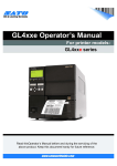
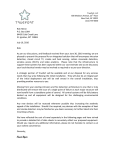
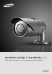
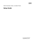
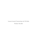
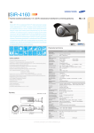
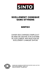
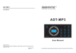
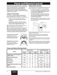
Antenna & Accessory Guide For HotPort Mesh Nodes and HotPoint Access Points Version 4.0 October 2014 The contents of this manual are subject to change without notice. Please refer to the Firetide website, www.firetide.com, for current information. © 2014 Firetide, Inc. - A Divion of UNICOM Global HotPort, HotPoint, HotClient, HotView, HotView Pro, MeshBridge, and AutoMesh are registered trademarks of Firetide, Inc. - A Divion of UNICOM Global. All rights reserved. Antenna Selection Guide Firetide offers the following tested and approved antennas. It is the user’s responsibility to insure compliance with all applicable laws in the country of operation. Note that some high gain antennas may exceed EIRP limits in some countries. Indoor antennas have RP-SMA connectors, compatible with Firetide HotPort indoor mesh nodes and HotPoint indoor access points. The outdoor antennas have N connectors. Band Staging 2.4 GHz Omni Model Gain Page ships w product 3 dBi 6 AO-024-MIMO-8 9 dBi 8 AOI 245-MIMO-25 2.5 dBi 10 4000-1111 AOI 245-MIMO-25 AO-050-MIMO-9 5 GHz Panel AO-050-N Sector Model Gain Page Model Gain Page AP-050-N 23 dBi 16 AS-050-N 16 dBi 23 AS90-050-MIMO-16T 14 dBi 24 7.5 dBi 11 4.5 dBi 10 8 dBi 12 AP20-050-MIMO-19 19 dBi 18 10 dBi 14 AP10-050-MIMO-23 23 dBi 20 AP5-50-MIMO-28 28 dBi 21 Firetide Connector Chart Firetide Model Number Antenna Connector Type Firetide Model Number Antenna Connector Type HotPort 5020-LNK N-female HotPoint 5100 Indoor AP RP-SMA HotPoint 5200 Outdoor AP N-female HotPort 7010 Indoor Mesh Node RP-SMA HotPort 7020 Outdoor Mesh Node N-female Firetide Antenna & Accessories Guide | Version 4.0 | October 2014 Page 2. Accessory Guide Cable Assembly CB-015-N Antenna Cable Assembly, 1.5 meter LMR-400 w/ Integrated lightning suppressor N-type con-nector CB-015-N-MIMO MIMO Antenna Cable Assembly for 5200 & 7020. 3 in 1 bundled 1.5 meter LMR-400 cables w/ Integrated lightning suppressor N-type connector CB-025-N-MIMO MIMO Antenna Cable Assembly for 5200 & 7020. 3 in 1 bundled 2.5 meter LMR-400 cables w/ Integrated lightning suppressor N-type connector CB-050-N Antenna Cable Assembly, 5 meter LMR-400 w/ Integrated lightning suppressor N-type connector CB-C-015-N Antenna Cable Assembly, 1.5 meter LMR-400 CB-C-015-N-MIMO MIMO Antenna Cable Assembly for 5200 & 7020. 3 in 1 bundled 1.5 meter LMR-400 cables CB-C-025-N-MIMO MIMO Antenna Cable Assembly for 5200 & 7020. 3 in 1 bundled 2.5 meter LMR-400 cables CB-C-050-N Antenna Cable Assembly, 5 meter LMR-400 Power Source & Cables PO-010-N 7000 series outdoor rated 10 meter North America AC power cable PO-010-E 7000 series outdoor rated 10 meter EU and Korea AC power cable PO-010-C 7000 series outdoor rated 10 meter China, Australia and New Zealand AC power cable PO-010-U 7000 series outdoor rated 10 meter UK, Singapore AC power cable 7020-1001 6 pin Female DC power connector for HotPort 7000 series 7020-1002 RF Terminator - 50 ohms - N male SP-POE-1 Indoor power injector for powering 5200/ 5020 series products Mounting Solutions MT-7100 HotPort 7000 family indoor mounting kit for wall, upright, ceiling and office panel installation, 10 machine screws SP-MNT-01 Replacement part for new panel antenna mounting bracket Spare Parts (Replacement Parts) SP-7200-03 7020 series Replacement outdoor clawtooth mounting kit SP-7200-04 7020 series outdoor rated replacement 5 meter North America AC Power cable SP-7100-01 7000 series Replacement indoor Power Supply Desktop Brick 12VDC SP-7200-02 7020 series Replacement weatherized field installable ethernet RJ45 connector Firetide Antenna & Accessories Guide | Version 4.0 | October 2014 Page 3. Waterproofing Instructions Most antenna problems are caused by coaxial cable connections that loosen due to vibration, allowing moisture to penetrate the connector interface. Firetide recommends that all outdoor cable connections be weatherproofed using butyl mastic, shown in Figure 1. Butyl mastic is a stretchy, slightly sticky material which bonds to itself and remains flexible. A layer of electrical tape is used underneath to keep the connection clean and make disassembly easier. Fig. 1 Materials Needed: tPliers tUtility knife tVinyl electric tape tRubber splicing/mastic tape (a.k.a. self-amalgamating, selfsealing, self-fusing, non-vulcanized) Waterproofing the Antenna Connection Step 1 Fig. 2 Ensure the connector and cables are free of foreign substances such as oil, water, grease, or dirt. Fasten connectors securely together. Use pliers to tighten. Then verify that Firetide node is working, using HotView™ mesh management software. Step 2 Tightly wrap a layer of electrical tape, STICKY SIDE OUT, over the connector from base of unit to one inch over the cable. When wrap-ping, the tape should overlap about 40% of the previous turn on each turn. This layer of electrical tape will ease removal of the mastic tape from the connector if required. Figure 2 shows the use of a pencil as a wrapping aid if space is tight. Fig. 3 Step 3 Tightly wrap a layer of butyl rubber splicing (mastic) tape over the electrical tape. Overlapping the tape about 40% on each turn, start from base of unit and extend at least one inch on to the cable sheath, as shown in Figure 3. The key to a good watertight connection is to maintain a high level of tension and stretch in the butyl rubber. Fig. 4 Step 4 Tightly wrap a layer of electrical tape over the butyl rubber mastic layer. Then wrap a second layer of electrical tape.The result should look like Figure 4. The outer layers of electrical tape prevent the mastic from melting in very hot weather. Your antenna connector is now weatherized. Next, weatherize the connection from the cable to the Firetide node. Firetide Antenna & Accessories 4 Firetide Accessory Guide Guide | Version 4.0 | October 2014 Page 4. 3.01 19 June 2009 Version Fig. 5a Waterproofing the Cable to Node Connections Waterproofing the connection of the cable to the lighning supressor and the lightning suppressor to the Firetide node is essentially the same process as the antenna connector. Step 5 Wrap a layer of electrical tape, STICKY SIDE OUT, around the supres-sor-to-node connection, as shown in Figure 5b and 5c. Repeat for the cable-to-suppressor connection. Fig. 5b Step 6 Using plenty of tension, tightly wrap a layer of butyl rubber splicing (mastic) tape over the electrical tape. Overlapping the tape about 40% on each turn, start from base of unit and extend at least one (1) inch on to the cable sheath, as shown in Figure 6. The key to a good watertight connection is to maintain a high level of tension and stretch in the butyl rubber. Fig. 5c Step 7 Tightly wrap two layers of electrical tape over the butyl mastic, sticky side in, as shown in Figure 7. Your system is weatherized. Don’t forget to leave a drip loop when installing the Firetide node and antenna. Fig. 6 Fig. 7 Firetide & Accessories VersionAntenna 3.01 19 June 2009 Guide | Version 4.0 | October 2014 Page 5. Reliable Connectivity Anywhere. 5 Firetide. Firetide 2.4 and 5.X GHz Dipole Staging Antenna The Firetide 2.4 and 5.X GHz Dipole staging antenna is shipped with the Firetide HotPort and HotPoint product line. These 3dBi indoor omnidirectional antennas assist in the network staging process and their easy-on-eye appearance blends smoothly with the Firetide hardware. Order Number 2.4 and 5.X GHz Dipole* * staging antenna ships with products NOTE: Staging antenna designed for indoor use only and recommend-ed application is to use in network staging process. continued on next page 2300–2500 MHz: VPol. 2500–2700 MHz: VPol. Electrical Specifications Value Frequency Range 2.4 – 5.X GHz Gain 3 dBi Radiation Pattern Omnidirectional VSWR (Voltage Standing Wave Ratio) ≤ 2.0 Impedance 50 Ω Polarization Vertical Operating Temperature -20°C – 65°C H Plane Mechanical Specifications Connector Type RP-SMA Firetide Antenna & Accessories Guide | Version 4.0 | October 2014 E Plane Page 6. Firetide 2.4 and 5.X GHz Dipole Staging Antenna continued from previous page Firetide Antenna & Accessories Guide | Version 4.0 | October 2014 Page 7. Firetide A0-024 MIMO-8 Omnidirectional Antenna The Firetide A0-024-MIMO-8 8dBi omnidirectional antenna is designed to provide maximum performance and reliability under the toughest weather conditions. The antenna features a UV-stable, vented radome that provides ultimate protection against weather elements. This antenna can be mast or ceiling mounted. Order Number AO-024 MIMO-8 Benefits • Vented system design. Provides reliable performance by protecting the electrical design against extreme moisture and/or temperatures. • Thread relief on connector. Improved accessibility for taping reduces installation time and improves overall effectiveness. • Internal o-ring seal in the base of the antenna with integrated connector at the base. Assures a watertight seal to prevent water from migrating into the antenna connector. Features • • • • • • High gain, low VSWR Small size, light-weight Sealed with fiberglass Suitable for 2.4 GHz WLAN, Wi-Fi system Wireless interface supported: IEEE802.11b,g,n Three 2.4 GHz ports continued on next page Electrical Specifications Value Frequency Range 2400—2500 MHz Bandwidth 100 MHz Gain 9 dBi Beamwidth E-Plane 10° H-Plane 360° Electrical Downtilt 10° Isolation ≤ 25 dB VSWR (Voltage Standing Wave Ratio) ≥ 1.5 Impedance 50 Ω Polarization Vertical Max. Power 20 W E-Plane Mechanical Specifications Connector Type N-Female Dimensions Ø145 mm x 600 mm Weight 2 Kg Pole Diameter Ø40 mm – Ø79 mm Firetide Antenna & Accessories Guide | Version 4.0 | October 2014 H-Plane Page 8. Firetide A0-024 MIMO-8 Omnidirectional Antenna continued from previous page 145 mm 145 mm 600 mm 600 mm Antenna "L" type bracket Mast (supplied by customer) Firetide Antenna & Accessories Guide | Version 4.0 | October 2014 Page 9. Firetide AOI-245 MIMO-25 Antenna Firetide AOI-245-MIMO-25 antenna is a dual-band, MIMO, ceiling mount antenna designed to provide maximum vertical polarization. This high performance antenna reduces overhead clearance requirements and comes in an attractive enclosure. At an affordable price , this antenna is an ideal choice for building public safety, retail establishments, enterprise networks, public “hot spots” and facilities anagement. It comes with a steel mounting kit. Order Number AOI-245 MIMO-25 Applications • • • 2.4G/5G WLAN system Support IEEE802.11a/b/g/n Indoor hotspot coverage Features • Suitable for indoor use • Ceiling mount • Space diversity, MIMO technique continued on next page Electrical Specifications Value Frequency Range 2400–2500/5150–5850 MHz Bandwidth 100/700 MHz Gain 2.5/4.5 dBi 2.4 GHz E Plane 2.4 H Plane 5 GHz E Plane 5 GHz H Plane VSWR (Voltage Standing Wave Ratio) ≤ 1.8/2.0 Impedance 50 Ω Polarization Vertical Max. Power 50 W Mechanical Specifications Connector Type RP-TNC Male/Custom Dimensions 145 mm x 42 mm Weight 300 g Mounting Ceiling Mount Firetide Antenna & Accessories Guide | Version 4.0 | October 2014 Page 10. Firetide AOI-245 MIMO-25 Antenna continued from previous page Firetide Antenna & Accessories Guide | Version 4.0 | October 2014 Page 10b. Firetide 4000-1111 2.4 GHz Omnidirectional Antenna This 7 dBi omnidirectional antenna is designed to provide maximum performance and reliability under the toughest weather conditions. The antenna features a UV-stable radome that provides protection against weather. Order Number 4000-1111 Typical Value Frequency Range 2.4-2.5 GHz Gain 7.4 dBi Nominal Impedance 50 ohms VSWR 1.5 Max Radiation Pattern Omnidirectional Vertical Beam Width 20° Polarization Vertical Connector N, female Operating Temp Range -20°C to 65°C Wind Survival 150 MPH Equivalent Flat Plate Area 7.1 sq. in. Lateral Thrust @ 125 MPH NA Bending Moment @ 125 MPH NA Height 17.5 inches (440 mm) Mounting Base Diameter 1 inch (25 mm) Weight 0.3 lbs (0.12 kg) Side View Beam Pattern Firetide Antenna & Accessories Guide | Version 4.0 | October 2014 Page 11. Firetide A0-050-MIMO-9 Omnidirectional Antenna The Firetide A0-050-MIMO-9 omnidirectional antenna is designed to provide maximum performance and reliability under the toughest weather conditions. The antenna features a UV-stable, vented radome that provides ultimate protection against weather elements. This antenna can be can be mast or ceiling mounted. Order Number AO-050 MIMO-9 Benefits: • Vented system design. Provides reliable performance by protecting the electrical design against extreme moisture and/or temperatures. • Thread relief on connector. Improved accessibility for taping reduces installation time and improves overall effectiveness. • Internal o-ring seal in the base of the antenna with integrated connector at the base. Assures a watertight seal to prevent water from migrating into the antenna connector. Applications: • 5 GHz Wlan, Wi-Fi system • IEEE 802.11a,n • Three 5 GHz ports continued on next page Electrical Specifications Value Frequency range 4900 – 6100 MHz Bandwidth 700 MHz Gain 8 dBi Beamwidth E-Plane 17° H-Plane 360° Electrical Downtilt 10° Isolation ≤ 25 dB VSWR (Voltage Standing Wave Ratio) ≥ 1.8 Impedance 50 Ω Polarization Vertical Max. Power 20 W 5 GHz E-Plane Mechanical Specifications Connector Type N-Female Dimensions Ø145 mm x 200 mm Weight 2 Kg Pole Diameter Ø40 mm – Ø70 mm Firetide Antenna & Accessories Guide | Version 4.0 | October 2014 5 GHz H-Plane Page 12. Firetide A0-050-MIMO-9 Omnidirectional Antenna continued from previous page 145 mm 145 mm 600 mm 600 mm Antenna "L" type bracket Mast (supplied by customer) Firetide Antenna & Accessories Guide | Version 4.0 | October 2014 Page 13. Firetide AO-050-N Antenna The Firetide AO-050-N antenna is a 12 dBi omnidirectional antenna designed to provide maximum performance and reliability under the toughest weather conditions. This antenna features a UV-stable that provides ultimate protection against weather elements. They can be mast or ceiling mounted. Order Number AO-050-N Features and Benefits: • Vented system design. Provides reliable performance by protecting the electrical design against extreme moisture and/or temperatures. • Down-tilt Mast mount kit reduces installation time and improves overall effectiveness. • Internal o-ring seal in the base of the antenna with integrated connector at the base. Assures a watertight seal to prevent water from migrating into the antenna connector. Applications: • 5.1/5.5/5.8 GHz WLAN System • 5.8GHz UNII/ISM System • WiFi Systems • Multipoint Applications Features: • 5.1/5.5/5.8GHz Tri-band • High Gain, Low VSWR • Supplied With a Down-tilt Mast Mount Kit continued on next page Electrical Specifications Value Frequency Range 5150—5850 MHz Bandwidth 700 MHz Gain 12 dBi Beamwidth E-Plane 10° H-Plane 360° VSWR (Voltage Standing Wave Ratio) ≥ 2.0 Impedance 50 Ω Polarization Vertical Max. Power 100 W E-Plane Mechanical Specifications Connector Type N-Female or N-Male Dimensions Ø25 mm x 600 mm Weight 550 g Pole Diameter ≤ Ø60 mm Firetide Antenna & Accessories Guide | Version 4.0 | October 2014 H-Plane Page 14. Firetide AO-050-N Antenna continued from previous page 20 mm Antenna Splint & Hose Clamp Mast ≤60 mm diameter (supplied by customer) 570 mm Connector Firetide Antenna & Accessories Guide | Version 4.0 | October 2014 Page 15. Firetide AP-050-N Antenna The Firetide AP-050-N is a directional panel antenna with wide spectrum coverage that provides a cost effective solution for high volume deployments. With an aluminum frame and ploycarbonate radome, it is rugged and highly sun and weather resistant, with an expected service life in excess of ten years. Order Number AP-050-N It is aesthetic; its small and unobstrusive profile blends easily with any environment. DC grounding for lightning protection helps to meet local building codes. Applications • 5.1/5.5/5.8GHz WLAN • Wireless Access systems • 5.8 GHz ISM applications • IEEE802.11a,g • WiFi • Wireless Bridges • Client Antenna Features • • • • • • • 5.1/5.5/5.8 GHz Tri-band High gain Low profile Light weight All weather operation DC Ground for lightning protection Supplied with a tilt and swivel mast mount kit continued on next page Electrical Specifications Value Frequency Range 4900–5875 MHz Gain ≥ 23 dBi Beamwidth E: 11° V: 11° VSWR (Voltage Standing Wave Ratio) ≤ 1.5 Impedance 50 Ω Polarization Vertical or Horizontal Max. Power 50 W E-Plane Mechanical Specifications Connector Type N-Female Dimensions 306x306x25 mm Weight 1.4 Kg (with brackets) Color White Mounting Pole Firetide Antenna & Accessories Guide | Version 4.0 | October 2014 H-Plane Page 16. Firetide AP-050-N Antenna continued from previous page Firetide Antenna & Accessories Guide | Version 4.0 | October 2014 Page 17. Firetide AP20-050 MIMO-19 Antenna AP20-050-MIMO-19 is a 19 dBi panel antenna that is best suited to 5 GHz deployments making it an ideal candidate for the large city-wide and other video surveillance applications. This low-profile antenna features rugged design with UVcoated Aluminum alloy and withstands the challenging outdoor conditions easily. Order Number AP20-050 MIMO-19 Applications • 5.8 GHz WLAN system • 5.8 GHz UNII/ISM system • Point to point, or point to multipoint Features • • • • • Broad band. 5.1/5.5/5.8/6.1 GHz Triple polarization MIMO application High gain, Low VSWR Strong corrosion resistance ability continued on next page Electrical Specifications Value Frequency Range 4900—6100 MHz Bandwidth 975 MHz Gain Vertical 19 dBi Dual Slant 16 dBi Horizontal Beamwidth Vertical 22° Dual Slant 20° Vertical Beamwidth Vertical 14° Dual Slant 19° F/B Ratio ≥ 25 dB Isolation ≥ 25 dB VSWR (Voltage Standing Wave Ratio) ≤ 1.8 Impedance 50 Ω Polarization ±45° and Vertical Max. Power 10 W E-Plane Mechanical Specifications Connector Type 3XN-type Female Dimensions 305x305x12 mm Weight 0.8 Kg (w/o clamps) Mounting Pole Firetide Antenna & Accessories Guide | Version 4.0 | October 2014 H-Plane Page 18. Firetide AP20-050 MIMO-19 Antenna continued from previous page Firetide Antenna & Accessories Guide | Version 4.0 | October 2014 Page 19. Firetide AP10-050-MIMO-23 Antenna AP10-050 MIMO-23 is a dual polarization MIMO antenna that is best suited to 5 GHz deployments making it an ideal candidate for the large city-wide and other video surveillance applications. This low-profile antenna features rugged design with UV-coated Aluminum alloy and withstands the challenging outdoor conditions easily. Order Number AP10-050 MIMO-23 Applications • 5.8 GHz WLAN system • 5 GHz UNII/ISM system • Point to point, or point to multipoint • Broad band. 4.9/ 5.1/ 5.5/ 5.8 GHz • MIMO application • High gain, Low VSWR • Strong corrosion resistance ability Electrical Specifications Frequency Range-MHz Value 4900— 5150 5150— 5500 5500— 5900 1000 MHz Bandwidth 20.5 dBi 22 dBi 23 dBi Horizontal Beamwidth 12 ° 11° 10 ° Vertical Beamwidth 12 ° 11° 10 ° Gain F/B Ratio ≥ 30 dB Isolation ≥ 27 dB VSWR ≤ 2.0 Impedance 50 Ω Polarization Max. Power Horizontal and Vertical 10 W Mechanical Specifications Connector Type 2 X N-type Female Dimensions 305 x 305 x 12 mm Clamp 1 Kg (w/o clamps) JM-RE +/- 30 ° ele. adj. Mounting Up to 12 cm diameter Weight Firetide Antenna & Accessories Guide | Version 4.0 | October 2014 Page 20. Firetide AP5-50 MIMO-28 Antenna The dual polarized AP5-50-MIMO-28 is a high precision parabolic dish antenna. The main advantage of this high gain antenna is the amazing precision for high directivity with narrow bandwidth. This makes it ideal for point-to-point links and for WLAN data communications. The antenna features rugged design with UV-coated aluminum alloy. Order Number AP5-050 MIMO-28 Applications • 4.9GHz Public Safety System • 5.1/5.5/5.8 GHz WLAN • Client Antenna • Wireless Bridge Features • High Precise Parabolic Dish • UV-Coated Aluminum Alloy • V/H Dual Polarization • Standard Mounting Kits continued on next page Electrical Specifications Value Frequency Range 4900—6100 MHz Bandwidth 950 MHz Gain 28 dBi Beamwidth Vertical 5° Horizontal 5° F/B Ratio ≥ 35 dB Isolation ≥ 28 dB VSWR (Voltage Standing Wave Ratio) ≤ 2.0 Impedance 50 Ω Polarization Vertical and Horizontal Max. Power 100 W E-Plane Mechanical Specifications Connector Type N-Female / N-Female Caliber Size Ø0.6 m Weight 5.5 Kg Pole Diameter Ø50–75 mm Firetide Antenna & Accessories Guide | Version 4.0 | October 2014 H-Plane Page 21. Firetide AP5-50 MIMO-28 Antenna continued from previous page 407 252 950 Firetide Antenna & Accessories Guide | Version 4.0 | October 2014 Page 22. Firetide AS-050 AS-050Specifications Specifications Firetide The Firetide AS-050-N is a directional 90-degree sector antenna with wide spectrum coverage that provides a cost effective solution for high volume deployments. To insure good coverage, it offers null fill in the elevations plane. With an aluminum frame and plastic radome, it is rugged and highly sun and weather resistant, with an expected service life in excess of ten years. Order Number AS-050-N It is aesthetic; its small and unobtrusive profile blends easily with any environment. DC grounding for lightning protection helps to meet local electrical building codes. Typical Value Frequency Range 4.9–6.1 GHz Gain 16 dBi Nominal Impedance 50 ohms VSWR 1.8 Max Radiation Pattern Directional Vertical Beamwidth Horizontal Beamwidth Ratio Front-Back 8° 90° Polarization Linear, Vertical Connector N type Operating Temp Range -40°C to 70°C Wind Survival NA Equivalent Flat Plate Area NA Lateral Thrust @ 125 MPH NA Bending Moment @ 125 MPH NA Size 22.6 × 3.7 × 2.1 inches (573 × 95 × 53 mm) Mounting Base MNT-22 (pole) Weight NA E-plane Beam Pattern 25 dB Firetide Antenna & Accessories Guide | Version 4.0 | October 2014 H-plane Beam Pattern Page 23. Firetide AS90-050 MIMO-16T Antenna AS90-050-MIMO-16T is a triple polarized directional 90-degree sector antenna. The triple polarization provides highest level of efficiency with minimum interference for optimum decorrelation. The radome is made of strong corrosion-resistant material to withstand tough outdoor environment. Order Number AS90-050 MIMO-16T Applications • 5.8 GHz WLAN system • 5.8 GHz UNII/ISM system • Point to point or point to multipoint Features • 4.9/5.5/5.8/6.1 GHz • Triple polarization • MIMO application • Medium gain, Low VSWR • Strong corrosion resistance ability continued on next page Electrical Specifications Value Frequency Range 4900–6100 MHz Bandwidth 1200 MHz Gain 14 dBi Beamwidth Vertical 8° Horizontal 90° Isolation ≥ 25 dB VSWR (Voltage Standing Wave Ratio) ≤ 1.8 F/B Ratio ≥ 20 dB Impedance 50 Ω Polarization ±45° and Vertical Max. Power 10 W E-Plane Mechanical Specifications Connector Type 3 × N-Female Dimensions 270 × 270 × 36 mm Weight 1.8 Kg (without clamps) Mounting Pole Firetide Antenna & Accessories Guide | Version 4.0 | October 2014 H-Plane Page 24. Firetide AS90-050 MIMO-16T Antenna continued from previous page Firetide Antenna & Accessories Guide | Version 4.0 | October 2014 Page 25. Firetide MT-7100 Bracket Order Number MT-7100 Firetide Antenna & Accessories Guide | Version 4.0 | October 2014 Page 26. Firetide SP-7200-03 Mounting U-bolt Kit • • • • • • • • M6x1.0, 40mm hex bolts M6x1.0, 20mm hex bolts M6 Nuts, SS M6 Flat Washers M6 Split Lock Washers Mounting U-bolts, 80mm Claw-tooth Pole Gripper Saddles M6 Wrench Order Number SP-7200-03 Mounting U-bolt, 80 mm M6 Wrench Claw-tooth Pole Gripper Saddle Firetide Antenna & Accessories Guide | Version 4.0 | October 2014 Page 27. 7020 Universal Mounting Bracket Install Guide Planning Your Installation Staging Considerations Using the provided temporary staging antennas, set up and test the HotPort nodes indoors, on a bench or table, before mounting them onto an exterior wall or pole. Pre-configure the nodes so that they are all on the same RF channel, etc. Use HotView Pro to configure the HotPort nodes and create a small mesh network. Test the network settings you plan to 1. Check to see that all nodes are visible in HotView Pro. If use. not, troubleshoot per directions in the HotView Reference Guide. 2. Set the Country Code for your country of operation. 3. Re-verify that all nodes are visible, and verify that dualradio nodes have both radios correctly meshed. Important! The staging antennas provided with Firetide outdoor HotPort nodes are for temporary use only. They MUST be replaced with outdoor-rated antennas as soon as the mesh is staged and operational. The staging antennas are NOT waterproof and NOT moisture resistant. If used outdoors, the antennas may fail. Contact your Firetide Reseller for assistance in selecting and ordering outdoor antennas suitable for your applications. For reference, your Firetide CD has a copy of Firetide’s Antenna & Accessory Guide. Other Important Considerations • It is often easier to install all devices onto a pole, and then attach the pole to the roof. In many cases, connecting the devices to a pole already attached to the roof top can be difficult and dangerous. • A lightning surge suppressor MUST be used. Some antennas include one, otherwise contact your Firetide Reseller to order a suitable suppressor. • Locate the HotPort close to the antenna; a short antenna cable gives better performance than a longer one. Firetide recommends antenna cables less than 3 meters. • The HotPort node and its antenna must both be grounded. • Use non-vulcanized rubber weatherproofing kits to weatherproof connectors and antennas. Preparing Earth Ground The HotPort node must be properly connected to earth ground. Failure to do so may result in equipment damage, injury, or death. The product warranty does not cover damages resulting in part or in whole from improper grounding. Consult your location’s building and electrical codes regarding antennas and follow them, or consult the National Electric Code (NEC). • If connecting HotPort to a tower or pole, connect the base of the tower pole directly to the building’s ground or to one or more approved grounding rods using 10 AWG ground wire and corrosion-resistant connectors. • Connect the grounding cable to rain gutters only if the rain gutter is properly connected to earth ground. Firetide Antenna & Accessories Guide | Version 4.0 | October 2014 • • • Ground rods should be copper, 1.8–2.4 m (6–8 ft) long. Install all grounding components in straight lines. If bends are unavoidable, do not make sharp turns. Earth-to-ground should not be more than 10 ohms. Antenna Placement Firetide recommends the use of antennas specifically designed for MIMO applications. While it is possible to select and mount six individual antennas, determining correct placement and spacing is difficult. Use an antenna engineered for best results with MIMO. Mounting Bracket HotPort node ships with a two-piece mounting bracket. This bracket is of the same design as the HotPort 6202 outdoor bracket, so you can install a 7020 in place of a 6201 or 6202. The assembly is shown below. The outer piece (the unversal mounting bracket) is secured by tabs and four thumb screws to the inner bracket, as shown below. Bottom view of a Firetide HotPort Thumb screw Universal mounting bracket Thumb screw (attached by thumb screws to the inner bracket) The universal mounting bracket is the outer of the two-piece mounting bracket attached to the back of the HotPort unit. The universal mounting bracket is secured by tabs and thumb screws to the above shown inner bracket. continued on next page Page 28. continued from previous page Mounting the HotPort Using the Universal Mounting Bracket Firetide’s HotPort can be mounted to a wall or onto a vertical or horizontal pole. The HotPort’s universal mounting bracket provides holes and slots for use with the provided mounting kit or for straps (not included) or other mounting methods. Before mounting, keep in mind that adequate space is needed around the mounting bracket to allow the HotPort unit to slide onto it and to enable cable connections. Remove the Universal Mounting Bracket from the HotPort The universal mounting bracket is shipped attached to the HotPort node. To remove the universal bracket, first loosen the four thumb screws, two on each side, then slide the universal bracket toward the connector side of the HotPort node and lift off. Wall Mounting Mount the universal mounting bracket to a wall using two holes near the top and two holes near the bottom of the universal bracket. Use appropriate screws (not provided) and anchors as required by wall construction and materials to safely and securely support the HotPort. Once the universal bracket has been mounted, attach the HotPort by reversing the bracket removal procedure. Pole Mounting POLE 37–50 MM DIAMETER Use Firetide’s SP-7200-03 u-bolt mounting kit, provided with each HotPort, to mount the universal mounting bracket onto a 37–50 mm diameter pole. 1. Using claw-tooth gripper saddles, washers, split washers then nuts, install the two u-bolts onto the mounting pole. Temporarily allow enough play to snuggly slide or spin the u-bolts on the pole. 2. Use the position of screw slots in the universal mounting bracket as a guide to correctly position the two u-bolts on the pole. For mounting stability, target screw slots that will allow the u-bolts to be positioned far from each other. 3. Once properly positioned, securely tighten the two u-bolts to the pole. 4. There should be about 12–15 mm (1/2–5/8”) of u-bolt threaded end sticking out beyond each nut. This is the bolt length needed to mount the universal bracket. If the lengths are longer, then on each u-bolt end, install a second nut until there is 12-15 mm of thread between the second nut and u-bolt end (see photos at right). 5. Slip a flat washer onto each of four u-bolt ends. 6. Attach the universal bracket by positioning the u-bolt ends into the bracket’s screw slots. Use washers, then lock washers and nuts to secure the universal bracket to the ubolts. 7. Recheck all nuts for adequate tightness. Confirm that the universal bracket does not slip or turn on the pole. 8. Attach the HotPort to the universal mounting bracket by reversing the bracket removal procedure. Firetide Antenna & Accessories Guide | Version 4.0 | October 2014 Universal mounting bracket attached to pole using u-bolts 12–15 mm U-bolt* mounted on pole—note addition of secondary nuts (circled) to meet 12–15 mm bolt length required by the universal mounting bracket. The HotPort universal mounting bracket can be mounted on vertical and horizontal poles using u-bolts* or other proper fastening hardware. Universal mounting bracket mounted onto a pole using two u-bolts* with additional secondary nuts. * —all u-bolts should be secured using proper washers & lock washers in addition to nuts. POLE GREATER THAN 50 MM DIAMETER Use appropriate mounting straps (not included) or other secure means to mount a HotPort universal mounting bracket onto a 50 mm (2.0”) or larger diameter pole, irregularly shaped pole, or light pole. 1. Position the universal mounting bracket against the pole. 2. Wrap a mounting strap around the pole and through the vertical slots located near the top of the universal mounting bracket. 3. Do the same with a second strap but this time use the vertical slots near the bottom of the universal bracket. 4. Secure the mounting straps so that the bracket will not slip or turn on the pole. 5. Attach the HotPort to the universal mounting bracket by reversing the bracket removal procedure. Page 29. Firetide Multiple Mount • • • • Mount Mounting Clamp Saddle M8x140 Bolts, with Flat and Lock Washers Does not include wall mounting expansion bolts or pole straps/worm gear clamps Multiple Mount Unit Order Number SP-MNT-01 WALL MOUNTING (expansion screws not included) Mounting Clamp Saddle with M8x140 bolts, flat and lock washers POLE MOUNTING pole 50–120 mm diameter MAST MOUNTING pole or mast greater than 120 mm diameter (straps/worm gear clamps not included) Firetide Antenna & Accessories Guide | Version 4.0 | October 2014 Page 30. Installation Tips An antenna is one of the most critical components in any RF communications system. Its performance determines the quality and the continuity of data flow in both directions. Antenna Basics The ideal antenna radiates the signal in all directions equally, like a sphere. Most real-world antennas are designed to concentrate or focus the radio signal in the preferred direction(s). The areas of focus are called beams or lobes. A common analogy is to compare an antenna to a sprinkler at the end of a hose. There is only so much water coming out of the hose but we can spread the water out or focus it to throw the water farther in a specific direction. The total is the same. The spray pattern can vary. Selecting Antennas In general, use the lowest-gain antenna adequate for the application. Do not go for gain indiscriminately. Choose an antenna that has an elevation beamwidth sufficient to cover all nodes, both near and far away. For long distances - 1/2 mile or more - directional high gain antennas must be used. These antennas must be as high as possible, and above obstructions such as trees and buildings. They must be aligned so their main lobes are directed at each other. High gain directionals have to be carefully aimed both in direction and elevation. Regulations regarding maximum antenna gains vary from country to country. It is the responsibility of the end user to operate within the limits of these regulations. The gain of an antenna is the degree of concentration it has. This is usually expressed as a ratio, comparing the antenna to the ideal spherical one. This ratio is called ‘dBi’. Real-world measurements of gain takes into consideration the losses in the antenna as well as its directional capabilities. A High Gain Antenna has greater directivity, i.e. it propagates RF energy more in one direction than others. This increases range and reduces the possibility of RF interference with other systems. Antenna Characteristics t 3BEJBUJPO1BUUFSO'BS'JFME 5IFåFMEQBUUFSOBUMBSHF distances. The far-field is also called the radiation field and is most important. t .BJO-PCF#FBN5IFEJSFDUJPOPGNBYJNVNJOUFOTJUZ t 4JEF-PCFT#FBN5IFSBEJBUJPOMPCFTJOBOZEJSFDUJPOPUIFS than that of the main lobe. t #FBNXJEUI5IFBOHMFXIFSFUIFNBKPSJUZPGUIFQPXFSJT radiated, usually defined as the angle between two half-power (-3 dB) points on either side of the main lobe of radiation. t 'SFRVFODZ#BOEXJEUI5IFSBOHFPGGSFRVFODJFTXJUIJO which the performance of the antenna, with respect to some characteristics, conforms to a specified standard. i.e. 802.11a,b&g Physical Obstacles Any physical object in the path between two antennas can cause signal attenuation. Common obstructions for outdoor installations include buildings and trees. Walls, whiteboards, metal objects and reflective glass between the two antennas are physical obstructions. Firetide Antenna & Accessories 24 Firetide Accessory Guide Guide | Version 4.0 | October 2014 Page2009 31. Version 3.01 19 June Caution! Risk of electric shock! POWER LINES CAN BE LETHAL Every year, people are killed by touching overhead power lines with metal poles or objects. Don’t be one of them. Do not install any HotPort product where contact with power lines can be made. People may be injured or killed if they are touching or holding any part of equipment when it contacts electric lines. Make sure there is NO possibility that equipment or personnel can come in contact directly or indirectly with power lines. ASSUME ALL OVERHEAD LINES ARE POWER LINES t Use approved non-conducting ladders, shoes, and other safety equipment. Make sure all equipment is in good repair. t If a tower or pole begins falling, don't attempt to catch it. Stand back and let it fall. t If antything such as a wire or pole does come in contact with a power line, DON’T TOUCH IT OR ATTEMPT TO MOVE IT. Instead, save your life by calling the power company. t MAKE SURE ALL TOWERS AND POLES ARE SECURELY GROUNDED AND ELECTRICAL CABLES CONNECTED TO ANTENNAS HAVE LIGHTNING ARRESTORS. The distance from a pole or antenna to the nearest power line should be at least twice the total length of the pole/antenna combination. This will ensure that the pole will not contact power if it falls either during or after installation. t The base of the antenna pole or tower must be connected directly to the building protective ground or to one or more approved grounding rods, using 10 AWG ground wire and corrosion-resistant connectors. TO AVOID FALLING, USE SAFE PROCEDURES WHEN WORKING AT HEIGHTS ABOVE GROUND IF AN ACCIDENT SHOULD OCCUR WITH THE POWER LINES t Select locations that will allow a safe and simple installation. t Assemble and test the antenna, HotPort unit, and all clamps and cables on the ground, before putting the mast or tower up. t %POUXPSLBMPOF t Refer to the National Electrical Code for grounding details. t DON'T TOUCH THAT PERSON, OR YOU MAY BE ELECTROCUTED Have someone call for medical help immediately! t Use a non-conductive dry board, stick, or rope to push or drag them so they no longer are in contact with electrical power. Firetide Limited End User Product Warranty Pursuant to all provisions described herein, Firetide antennas are warranted for one (1) year from the date of purchase against defects in the build materials and workmanship. Firetide does not warrant that the Products will meet any requirements or specifications of any End User Customer. This warranty applies to Firetide antennas. The above warranties are void if the alleged defect cannot be verified by Firetide or if, as determined by Firetide, the product failure was due to tampering, abuse, misuse, accident, shipping, handling, or storage; or if the product has been installed, used, or maintained in a manner not described in the product user manual; or if the product has been altered in any way; or if product serialization has been altered. Any attempt to disassemble or repair the product by anyone other than Firetide immediately voids this warranty. This warranty applies only to the original End User purchaser of the product and may not be transferred to any other individual or entity. (including, without limitation, damages for loss of profits, business interruption, loss of information, or other pecuniary loss) arising out of the use or inability to use the product or the performance, interruption or failure of the product, irrespective of the cause of action, even if Firetide has been advised of the possibility of such damages. Firetide’s cumulative liability for all claims arising out of or in connection with this warranty will not exceed the amount paid by the original End User purchaser to purchase the product. The amounts payable for the product are based in part on these limitations and these limitations shall apply notwithstanding the failure of essential purpose of any remedy. Some jurisdictions do not allow the exclusion or limitation of incidental or consequential damages, so to that extent the above limitations or exclusions may not apply to you. By using the product the original End User purchaser agrees to and is bound by these terms and conditions. In the event that a product fails to meet this warranty and Firetide’s authorized reseller is notified in writing of such failure within the warranty period, Firetide shall, at its own discretion, either repair the product or replace it with the same or a functionally-equivalent product free of charge. Replacement products may contain refurbished materials in whole or in part. Firetide will honor this warranty provided the product is returned through an authorized Firetide reseller or dealer with shipping charges prepaid, along with a proof of purchase describing the original purchase date and product serial numbers if applicable. The authorized reseller must acquire a Return Materials Authorization (RMA) number from Firetide prior to returning any product. Firetide In no event will Firetide be liable for any special, incidental, consequen-tial, does not accept shipments of defective products without shipping charges prepaid. punitive or indirect damages whatsoever THE FOREGOING ARE THE EXCLUSIVE WARRANTIES APPLICABLE TO THE PRODUCT INCLUDING THE SOFTWARE, AND THE EXCLUSIVE REMEDY FOR DEFECTS IN THE PRODUCT. FIRETIDE DISCLAIMS ALL OTHER WARRANTIES, WHETHER EXPRESS, IMPLIED, STATUTORY OR OTHERWISE, INCLUDING BUT NOT LIMITED TO IMPLIED WARRANTIES OF MERCHANTABILITY, NON-INFRINGEMENT OR FITNESS FOR A PARTICULAR PURPOSE. SOME LAWS DO NOT ALLOW THE EXCLUSION OF IMPLIED WARRANTIES SO TO THAT EXTENT THIS LIMITATION MAY NOT APPLY TO YOU. Firetide Antenna & Accessories Guide | Version 4.0 | October 2014 Page 32.