1
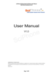
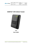
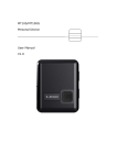
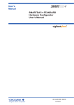
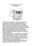
Version Number
Modified by
Change Content Type
Date
V1.0
Amy
create
2014.06.23
GPS Multi-function Tracker User Manual
GPS
Multi-function Vehicle Positioning Tracker
_______________________________________
___
User manual
1
CONTENTS
1. PRODUCTS OVERVIEW················································································ 2
2. SAFETY INSTRUCTION················································································ 3
3. SPECIFICATION AND PARAMETER ······························································ 3
4. GETTING STARTED ····················································································· 4
4.1. HARDWARE AND ACCESSORIES ······································································· 4
4.2. VIEW AND PORT ························································································· 5
4.3. FIRST USE ································································································ 5
5.
PARAMETER SETTING BY SMS ································································· 7
5.1
CHANGE THE PASSWORD ··············································································· 7
5.2
AUTHORIZED NUMBER ·················································································· 8
5.3
DEFINITE TIME TRACK ·················································································· 8
5.4
SOS EMERGENCY CALLING ············································································ 9
5.5
TRACKING BY GPRS···················································································· 9
5.6
GEO-FENCE ······························································································ 9
5.7
SET THE TIME ZONE ·················································································· 10
5.8
TRACKING BY SET THE DISTANCE OR ANGLE······················································· 10
5.9
INPUT APPLICATION/IGNITION DETECTOR ························································· 10
5.10 FUEL DETECTOR ······················································································· 11
5.11 OUTPUT CONTROL COMMAND ········································································ 11
5.12 OUTPUT APPLICATION ················································································ 12
6. SET THE SOFTWARE·················································································· 12
7. INSTALL THE DEVICE················································································ 13
7.1. INSTALL I/O WIRE ···················································································· 13
7.2. INSTALL LCD ·························································································· 14
7.3. INSTALL TEMPERATURE SENSOR ····································································· 14
7.4. INSTALL CAMERA ······················································································ 15
7.5. INSTALL RFID CARD READER ········································································ 15
7.6. TWO-WAY COMMUNICATION ········································································· 16
7.7. VOICE BROADCAST ···················································································· 16
8. PROBLEMS AND SOLUTIONS····································································· 17
2
1. Products overview
Thanks for purchasing our products!
Tracker is a GPS/ GPRS based tracking device designed for heavy motorbike, intercity bus,
school bus and fleet management.
It has built-in terminals of GPS module and GSM communication module, which are used for
getting the location data and send it to authorized phone number via SMS, and tracking
through free maps Google Earth or Google Map; at the same time, the GPRS data can be sent
to the internet server, which can realize the checking, monitoring and managing of the device
on computer.
Tracker has the following features and functions:
◆Collision alarm
◆3G accelerometer
◆Tracking regularly
◆Geo-fence alarm
◆Over speed alarm
◆Low battery alarm
◆SOS emergency calling
◆Low battery alarm
◆No GPS signal alarm
◆Build in 1GB memory IC
◆Internal battery 750mAh
◆Tracking by distance
◆Build in 8MB flash memory
◆GPS antenna cut off alarm
◆External power cut off alarm
◆Fuel/engine cut off remotely
◆Camera for taking photograph (optional)
◆Navigation LCD panel (optional)
◆RFID card reader (optional)
◆Tracking by SMS/GPRS (TCP/UDP)
◆Remotely monitoring or two-way communication
◆Two ways(DS18B20)temperature measurement (optional)
◆Three digital outputs, three digital inputs and two analog inputs, four RS232 ports, one RS485 port
3
2. Safety instruction
Read these simple guidelines. Not following them may damage the tracker or not perform
proper function of application.
Correct Connection
When connect to
Chosen Accessories
Power off in Blasting Site
Use our accessories, battery and external module to avoid damage to
our device
In order to avoid damage by external force
intentionally, please install our device in a hidden place
Follow related restrictions. Do not use our device in blasting site
Repair and Service
Only qualified engineer with technical support can repair our device
Not Fully Water Resistance
The device is not fully water resistant. Keep it dry
Installation in a Hidden Place
other devices, please read its manual carefully
3. Specification and parameter
Items
Power supply
Backup battery
Normal Power Consumption
Size
Weight
Operating Temperature
Humidity
Specification
DC 9-33V/1.5A
Rechargeable battery 750mAh (3.7V)
70mA
84 mm*66 mm*30 mm
135g
-20 ~ +55 °C
5% ~ 95% (Non-condensing )
GSM Module
GPS IC
GPS sensitivity
GPS frequency
C/A code
Channel
Positional accuracy
Quad band GSM 850/900/1800/1900 MHz
UBLOX GPS IC
-161dB
L1, 1575.42 MHz
1.023 MHz
50 channels
<10 M, 2D RMS
Speed accuracy
Time accuracy
Turnover time
Hot start
Warm start
Cold start
Maximum altitude
0.1 M/S
Satellite Time: 1 microsecond time synchronization
Average 0.1s
Average 1s
Average 3s
Average 37s
18,000M (maximum 60,000 feet).
Maximum speed
Maximum acceleration
500 m/s (maximum 1000 knots).
Less than 4g
Working time
LED
Button
About 7 hours
3 LED lights to show Power, GPS and GSM status
SOS button for making phone calls, sending position
and giving a warning SMS
3 digital outputs
3 digital inputs
2 analog inputs
4 RS232 ports
1 RS485 port
Port
4
4. Getting Started
This section will describe how to set the tracker.
4.1. Hardware and accessories
Standard accessories:
Terminal
(Battery included)
I/O connecting wires
GSM antenna
GPS antenna
CD
USB cable
Optional accessories:
Navigation
LCD panel
Navigation LCD
panel (PND)
RFID card reader
Two-ways temperature sensor
Camera
(At most support three-ways)
Headset with microphone
5
4.2. View and port
GPS antenna port
GSM antenna port
Power switch
Camera 1
I/O port
SIM card slot
Camera 2
LCD
Camera 3
Micro USB port
RS485(RFID) Speaker port
Temperate sensor
Two-way communication port
4.3. First use
Please read this manual before using tracker and check if all parts are included in the
packaging box.
4.3.1 Ensure that your tracker has a working SIM card installed and turn the power switch on.
√
6
- Our device only supports micro SIM card,if it is large,please go to the local operator and
cut it become the micro SIM card(do not cut to the nano SIM card)
- Check the SIM card has not run out of credit money (please test the SIM card in a phone to
make sure it can send and receive SMS)
- Make sure that lock code of the SIM card is turned off
- If you need the function of sending an SMS location report to the authorized phone number
when it makes a call to the tracker, please make sure the SIM card installed supports
displaying caller ID
Insert the SIM card:
--Unscrew the front cover of the tracker, as follow:
Attention: The device must be turned off when you insert the SIM card
Please make sure the bevel edge of the SIM card is outward and its metal surface facing down
when you find the SIM card slot and insert it, then slide the power switch to left and turn it on.
As follow:
OFF
micro SIM
ON
4.3.2 Connect the antenna
- connect the GSM antenna to the golden port
Attention: the GSM antenna is omni-directional antenna so that it can be installed far away
from the power source and anywhere hidden in the car.
-connect the GPS antenna to the white gold port
Attention: GPS antenna is directional antenna. It is better to fix it to face the sky directly and
flat side down, black side up, and use double-side tape keep it fixed, otherwise the
GPS signal will be affected.
7
4.4 LED indication
Red – Power indication
Always On
Power charging
Always OFF
Power charging completed or no power
Blue – GSM indication
0.3S On and 0.3S Off
GSM module is initializing or calling in
Always On
GSM network is not registered
1S On and 3S Off
GSM network is registered
0.1S On and 3 S Off
GSM network is registered network and GPRS
function works well
Yellow – GPS indication
0.3S On and 0.3S Off
GPS module is initializing
1S On and 3S Off
GPS module is working normally but hasn't fixed
position
0.1S On and 3S Off
GPS module is working normally and has fixed
position
5. Parameter setting by SMS
5.1 Change the password
SMS Command: $SMS,000000;W001,123456;!
Describe: change user password
Explain:
All the SMS commands must be capitalized and please switch to English input method when
you edit.
1. ‘000000’ is user’s password, the default password is ‘000000’. Device will only accept
commands from a user with the correct password. Otherwise command will be ignored
2.
‘123456’ is the new password, password must be 6 digits
For example:
$SMS,000000;W001,123456;!
8
5.2
Authorized number
SMS Command: $SMS,000000;W010,NO., Phone Number,ABCDEFGHIJKLMNOP;!
Describe: set the authorized phone numbers to receive SMS alarms
Explain:
NO.: serial number, must be 1 or 2 or 3
Phone Number: authorized phone numbers, Max. 16 digits
A SOS
B IN1
C IN2
D IN3(ACC)
E Cut external power off alarm
F Low battery alarm
G Car battery is low alarm
H Geo-fence alarm
I Receive GPS signal alarm
J Lost GPS signal alarm
K Cut GPS antenna off alarm
L Over speed alarm
M Hitting alarm
N Tracking by calling
O Answer the phone automatically
P Fatigue driving warning;(1: enable; 0: disable)
For example:
Set the first authorized phone number is 13800000000,and just enable SOS alarm function.
$SMS,000000;W010,1, 13800000000,1000000000000000;!
5.3 Tracking by preset time interval
SMS command: $SMS,000000;W013, Phone Number,X,Y;!
Describe: set the time interval and the number of times of sending SMS
Explain:
1. X: stand for time interval(Max. is 65535), unit is minute
2. X=0 means disable this function
3. Y means the number of times of sending SMS
4. Y=0 means device will send unlimited SMS
For example:
$SMS,000000;W013,13800000000,30,0;!
When enable it, tracker will send location SMS to every authorized phone number.
9
5.4
SOS emergency calling
SMS command: $SMS,000000;W011, Num;!
Describe: if press SOS button for 3 seconds,the tracker will call the SOS phone number
Explain:
Num: phone number(Max. 16 digitals )
For example:
$SMS,000000;W011, 13500000000;!
Set the SOS number is 13500000000
5.5
Tracking by GPRS
SMS Command:
$SMS,000000;W002,APN,Username,Password;W003,IP,Port;W004,ID;W005,X;W009,Y;!
Description: enable GPRS tracking function.
Explain:
1.
APN: access point name of network
2.
Username and Password are optional. If you don’t know what they are, please just input
APN only
3.
APN + Username + Password should not be over 64 characters
4.
IP: server’ IP address or domain name
5.
Port: Max. 65535
6.
ID: device ID
7.
X: GPRS upload interval, unit is seconds
8.
Y: GPRS upload mode, range of: 0~2
0 means disable GPRS function, 1 means upload by TCP, 2 means upload by UDP
Example:
$SMS,000000;W002, cmnet,,;W003,192.168.1.1,8088;W005,60;W009,1;!
5.6
Geo-fence
SMS command: $SMS,000000;W018, NO.,name,lat,lng,radius;!
Describe: enable Geo-fence alarm. When the tracker moves in/out the preset geo-fence,
tracker will send an alarm by SMS to the authorized number and send this data to
server if GPRS is connected.
Explain:
NO.: serial number for geo-fence must be 1 to 5
name: max. 10 characters
lat: Latitude, format is dd.dddddd, the unit is degree, if it is northern latitude, minus is needed.
Otherwise, omit it
10
lng: Longitude, formats is ddd.dddddd, the unit is degree, if it is east longitude, minus is
needed. Otherwise, omit it
radius: Max. 99999.00, the unit is Km
Based on preset longitude and latitude as the center of the circle, and the preset radius, a
circle is defined.
For example:
$SMS,000000;W018,1,school,22.12345,114.12345,10.50;!
$SMS,000000;W018,2,office,12.12345,-45.12354,10.75;!
5.7
Set the time zone
Set the time zone of SMS
SMS command: $SMS,000000;W020,X;!
Describe: Choose time zone of SMS, time zone default is GMT 0.
Explain:
X=time zone value, please plus"-"in front if it is a negative, otherwise, ignore it. Unit is
minutes (New York’s time zone is -300minutes)
For example:
$SMS,00000;W020,480;!
5.8 Tracking by distance or angle
SMS Command: $SMS,000000;W006,X;W007,Y;!
Describe: this command used for enable this function.
X is distance value, unit is meter; Y is angle value, unit is degree (Suggest X=100 Y=15)
For example:
$SMS,000000;W006,100;W007,15;!
5.9
Input application/Ignition detector
Power for ignition
ACC
Ignition switch
Battery
Digital input 3 (ACC) used for ignition detection. The detection flag and alarm will be sent
to the server through GPRS when flag changes. Please refer to <GPRS Communication
Protocol> for more information.
11
5.10 Fuel detector
VCC
AIN1/AIN2
GND
Analog input(AIN1)used for oil detection, range 0-3V. If there is other sensor you want to use,
please make sure its voltage is suitable. Oil value is the one with highest precision, Max.
212 .The remaining-oil-percent will be sent to the server via GPRS.
The remaining-oil-percent = (AIN1/4096)*100%
AIN1 value is the data to be uploaded to server by GPRS.
Please refer to <GPRS Communication Protocol> for more information.
5.11 Output control command
SMS command: $SMS,000000;W022,NO.,X;!
Describe: enable/disable this output
Explain:
NO.: 0~4 (1 refer to digital output 1, 2 refer to digital output 2, 3 refer to digital output 3,
4 refer to digital output 4)
X=1: open the output so that it can drive the relay.
X=0: close the output.
For example:
$SMS,000000;W022,1,0;!
12
5.12 Output application
+12V DC
White
Relay
85
IN4007
Relay
30
87
86
OUT1/OUT3
P1
Battery
P2
P1
Green
P2
Yellow
Power for ignition
Engine ignition loop
Trackers default output OUT1/OUT3 are closed, in this case P1 and p2 are connected inside
the relay: when the output is open, relay is disconnected, so we can control engine’s ignition
loop.
For example:
$SMS,000000;W022,1,1;! (Engine ignition loop disconnected)
$SMS,000000;W022,1,0;! (Engine ignition loop connected)
Please refer to <A command list> for more information.
6. Setup software
In addition to set the tracker parameter with SMS, we can set it on the PC computer with
<Setup software>.
13
7. Install the device
7.1. Install I/O wire
I/O port
Identifying
Function
1 VCC
red
2
3
4
5
DC IN
Input voltage: 9 ~ 33V/1.5A
Ground
SOS emergency button
Ground
black
orange
black
brown Digital input 1(positive triggered)
GND
SOS
GND
IN1
6 IN2
7 ACC
8 OUT1
white
purple
green
9 OUT2
yellow
10 OUT3
pink
11 AIN2
grey
12 AIN1
blue
Digital input 2(positive triggered)
Digital input ACC(positive triggered)
Digital output 1, used for control relay or other
(drivable electricity: 500 mA, withstanding voltage 50V)
Digital output 2, used for control relay or other
(drivable electricity: 500 MA, withstanding voltage 50V)
Digital output 3, used for control relay or other
(drivable electricity: 500 MA, withstanding voltage 50V)
Analog input 2, general connect engine temperature sensor,
input voltage: 0 ~ 3V (can customize other electric
voltages)
Analog input 1, general connect fuel sensor
input voltage: 0 ~ 3V (can customize other electric
voltages)
14
7.2. Install Navigation LCD Panel (PND)
LCD uses resistive screen, it supports road navigation, making a phone call, send and receive
SMS, and send target location remotely, etc. (Please connected the external power when you
use it).
1
2
3
4
5
6
Red
Dangling
Green
Dangling
Yellow
7
8
Blue
White
+5V
DC IN is 5V when tracker connect to the external power source
RS232 RX
Port of LCD receiving data
RS232 TX
Port of LCD sending data
GPS RX
GND
Port of receiving GPS data
Ground
Dangling
7.3. Install temperature sensor
It uses DS18B20, the measuring range of temperature is +125℃ ~ -55℃; up to support two
ways temperature sensor. Waterproof and the longest wire length can be customized to 5m.
1
Black
GND
Ground
2
Yellow
T2
Temperature detection has two ways output, this is second way
3
Red
VCC
Power output’s port (also can work normally without external power source)
4
Yellow
T1
Temperature detection has two ways output, this is first way
15
7.4. Install camera
Tracker supports three ways photographing and auto-light compensation at night. Its working
voltage is 5V.
Attention: if you want to take a photograph, please make sure the tracker connected the
external power.
Standard configuration is three ways RS232 connected camera, RS232’s port also can be
customized to connect other equipments.
1
Black
GND
2
Greed
3
Red
+5V
The power output port (only when connected the external power source, the power
output voltage is 5V)
4
Yellow
RS232 RX
RS232 receive port
RS232 TX
Ground
RS232 send port
7.5. Install RFID card reader
It uses RS485 bus communication, convenient to add other RS485 equipments, working
voltage is 5V. It can be enabled only when engaged with an external power source.
1
2
3
Black
Greed
Red
GND
RS485 A
+5V
4
Yellow
RS485 B
Ground
RS485 A V+
The power output port (only when connected the external power source, the power
output port is 5V)
RS485 B V-
16
7.6. Two-way communication
The two-way communication function can only be enabled when use the headset with
microphone for Apple, Samsung, MINU, Huawei etc.
7.7. Voice broadcast
Tracker supports TTL voice broadcast, but this function must be customized, our standard
configuration is not including this.
17
8. Problems and solutions
Problem:Tracker can not turn power switch on
Possible cause
resolution
Low battery
Please connect external power
Problem: The tracker do not reply the SMS
Possible cause
resolution
The GSM antenna conjunction
isn't connected firmly
The GSM antenna conjunction is
incorrect
Please reconnect the GSM antenna
The GSM network is busy
Wait for a message. The GSM network may reply slowly when busy time
or equipments breakdown
Password or command is wrong
Please use correct password and command format
Not enough SIM balance
Please change or recharge the SIM card
The SIM damaged or warped
Please check the SIM card, sweep metal of card to get in touch with a
point, If still invalid then replace SIM card
Make sure the GSM antenna and the GSM connecting base are connected
Problem: SMS received with latitude and longitude for zero
Possible cause
resolution
The GPS antenna conjunction isn’t
connected firmly
The GPS antenna conjunction is
incorrect
The tracker has already blocked
the GPS signal
Please reconnect the GPS antenna
The GPS signal is weak
Place the GPS antenna face to the sky
Make sure the GPS antenna links the GPS conjunction
Move the tracker to open area w/o any tall building, tree and heavy
raining. Those can shield GPS signal
problem:Can not connect the server by GPRS
Possible cause
resolution
The SIM card can not support the
GPRS function
Enable the SIM card’s GPRS function
The GPRS function has been
disable
Incorrect IP address or PORT
Enable the GPRS function
The GSM signal is weak
Move the tracker to a place with strong GSM signal
Get the right IP address and port, then reset the device