1
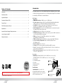
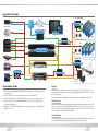
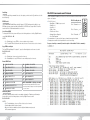
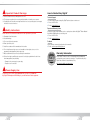
Rev 0 – Feb 2015
KD-4x4CSK / KD-8x8CSK
Key Digital®, led by digital video pioneer Mike Tsinberg,
develops and manufactures high quality, cutting-edge
technology solutions for virtually all applications where
high quality video imaging is important. Key Digital®
4/8 Inputs to 4/8 Outputs HDMI Matrix Switchers,
Audio De-embedders of Coaxial Digital & Analog L/R,
support Ultra HD/4K
is at the forefront of the video industry for Home Theater
Retailers, Custom Installers, System Integrators,
Broadcasters, Manufacturers, and Consumers.
Operating Instructions
KD-4x4CSK
KD-8x8CSK
The Experts in Digital Video Technology and Solutions™
Key Digital® Systems :: 521 East 3rd Street :: Mount Vernon, NY 10553
Phone : 914.667.9700
Fax : 914.668.8666
Web : www.keydigital.com
4
1
Table of Contents
Introduction
Introduction . . . . . . . . . . . . . . . . . . . . . . . . . . . . . . . . . . . . . . . . . . . . . . . . . . . . . . . . . . . . . . . . 1
Key Digital® Champion Series™ KD-4x4CSK/KD-8x8CSK are HDMI Matrix switchers capable
Quick Setup Guide . . . . . . . . . . . . . . . . . . . . . . . . . . . . . . . . . . . . . . . . . . . . . . . . . . . . . . . . . . 2
Application Example . . . . . . . . . . . . . . . . . . . . . . . . . . . . . . . . . . . . . . . . . . . . . . . . . . . . . . . . . 3
Connections, Buttons & LEDs . . . . . . . . . . . . . . . . . . . . . . . . . . . . . . . . . . . . . . . . . . . . . . . . . . 4
Remote Control . . . . . . . . . . . . . . . . . . . . . . . . . . . . . . . . . . . . . . . . . . . . . . . . . . . . . . . . . . . . . 5
RS-232 Commands and Protocol . . . . . . . . . . . . . . . . . . . . . . . . . . . . . . . . . . . . . . . . . . . . . . . 7
of switching 4/8 independent Inputs/Sources to 4/8 independent Outputs/Zones and feature
de-embedding of HDMI audio for external distribution.
Key Features
›› HDMI Matrix Switching: 4/8 HDMI sources to 4/8 HDMI outputs
›› Resolution Support: Supports all SD, HD, and VESA (VGA, SVGA, XGA, WXGA, SXGA,
UXGA) resolutions up to UHD/4K (4Kx2K/60[4:2:0], 4Kx2K/30/25/24[4:4:4])
›› Ultra HD/4K: 4K/2K video resolution support for 4K-capable televisions and commercial
applications such as Digital Movie Theaters, CAD, Post Production
Specifications . . . . . . . . . . . . . . . . . . . . . . . . . . . . . . . . . . . . . . . . . . . . . . . . . . . . . . . . . . . . . . 9
›› Audio De-Embedder: Audio from the selected HDMI input may be de-embedded through the
Important Product Warnings & Safety Instructions: . . . . . . . . . . . . . . . . . . . . . . . . . . . . . . . . 10
›› 3D Ready: Capability to pass 3D stereoscopic signal formats
›› Full Buffer System™: Manages TMDS re-clocking / signal re-generation, HDCP authentication to
How to Contact Key Digital® . . . . . . . . . . . . . . . . . . . . . . . . . . . . . . . . . . . . . . . . . . . . . . . . . . 11
Warranty Information . . . . . . . . . . . . . . . . . . . . . . . . . . . . . . . . . . . . . . . . . . . . . . . . . . . . . . . . 11
Coax digital (PCM) or Analog L/R audio output
source & display, and EDID Control handshake
›› EDID: Internal library with 15 default EDID configurations for input, in addition to
native EDID data for any Output/Display
›› TMDS re-clocking: Support for long HDMI connectivity using Key Digital® HDMI cables
›› Lossless Compressed Digital Audio: Dolby® TrueHD, Dolby® Digital Plus and
››
››
››
››
DTS-HD Master Audio™
Deep Color Support: Up to 12 bits/color
Licensing: Fully licensed and compatible with all HDMI and HDCP technologies
Control: Front panel buttons/LEDs, Serial IR, Optical IR, and RS-232 Control, including discrete
power on and off via IR and RS-232
Major Control System Support: Compass Control®, AMX®, Control4®, Crestron®, Extron,
Leviton®, RTI®, Savant, URC®, etc.
Accessories
›› Power Supply: (KD-4x4CSK) KD-PS12V2A 12V/2A DC Power Jack, Srew In Type,
››
››
››
››
››
(KD-8x8CSK) KD-PS12V5A 12V/5A DC Power Jack ( 2.1mm ), Screw In Type
Remote Control
(8/16) HDMI Lacing Clips
1 Loosen
Screw
Rack Ears
Operating Instructions
2 Slide Clip
on to Screw
Warranty Card
Rack Mounting
Always follow the instructions provided in this Operating Manual.
© 2015 Key Digital, Inc. All rights reserved.
Secure the rack ears to each side of the
KD-4x4CSK/KD-8x8CSK with the supplied
hardware then fasten the unit to the rack rails
with the included machine screws.
4
Insert Key Digital®
HDMI® Cable
5
Fasten HDMI Cable to Clip
with Cable Tie
3
Secure
Screw
2
3
Application Example
Reception Area
iPad
HDMI
RJ45
WiFi
RJ45
Ultra HD/4K
Digital Signage
KD-X400Prok
Router
x4
Ethernet
KD-MC1000 x2
HDMI
KD-CSLX1
RJ45
Visualizer
x4
IR
Master Controller
IR
Displays
Conference Room
KD-X400Prok
HDMI
HDMI
IR
HDMI
IR
HDMI
x3
CAT5e/6
HDMI
RS-232
IR
KD-8x8CSK
HDMI
Satellite x3
HDMI
Speakers
HDMI
Displays
Boardroom
IR
Red-Ray
L/R
KD-X600Prok
RS-232
HDMI
IR
Multi-Zone Amp
HDMI
HDMI Laptop
KD-VCS500
VGA
L/R
HDMI
KD-X600Prok
PCM
HDMI
HDMI
RS-232
PCM
Projector
CAT5e/6
Surround
Sound
AVR
VGA Laptop
Quick Setup Guide
Operation
1. Begin with the KD-4x4CSK/KD-8x8CSK and all input/output devices turned off with power
cables removed.
After performing the setup above, the unit is ready for operation. There are several options for
controlling the unit. Commands can be issued via Serial IR, Optical IR, and RS-232, or by using
the front panel buttons.
›› Note: Many advanced commands for setup and/or operation are available only via RS-232.
2. Connect HDMI sources to the appropriate input ports on the KD-8x8CSK.
3. Connect display devices to the HDMI output ports and audio devices to audio output ports.
4. Connect power to the KD-4x4CSK/KD-8x8CSK as well as to all other input and output
devices and turn them on.
5. Operate the KD-4x4CSK/KD-8x8CSK switcher via front panel buttons, Serial IR, Optical IR,
and RS-232 control.
IR Emitter Control
When using an IR Emitter / IR Extender (sold separately), the IR Emitter must be mounted over the
IR Sensor on the front of the KD-4x4CSK/KD-8x8CSK. One end of the cable is connected to the
IR Receiver / Master Controller / IR Extender / IR Connecting Block, while the other end is mounted
over the IR Sensor of the KD-4x4CSK/KD-8x8CSK.
Serial IR Operation
The unit may also be controlled via the Serial IR interface, providing a hard-wired IR connectivity.
Use a 3.5mm Male Mono plug with the IR signal carried on the tip of the connector.
4
5
Connections, Buttons & LEDs
Front Panel Operation
Output Select Buttons
Rear Panel Connections
All connections to the KD-4x4CSK/KD-8x8CSK are found on the rear panel of the units. Refer to
the illustrations below for port assignments while making connections.
Serial IR
RS-232
Input LEDs
HDMI Inputs & LEDs
HDMI & Audio Outputs & LEDs
Power
›› HDMI Inputs: The HDMI Inputs are located on the left side of the back panel. The Inputs have a
blue LED that will illuminate solid during active link (voltage + data link)
›› HDMI Outputs: The HDMI Outputs are located on the right side of the back panel. The Outputs
have a blue LED that will illuminate solid during active link (voltage + data link)
›› The RS-232, Serial IR, and Power connections are located on the right side of the back panel.
Audio Outputs
There are 4/8 Output buttons along the front panel.
Pressing an output button will select the next HDMI input.
A blue LED will indicate which Input has been selected for each Output.
Front button control can be disabled/enabled via RS232 if desired.
The Optical IR window is located on the right side of the front panel receives
IR remote control signals.
›› Notes:
»» Front LEDs will scroll during boot up
››
››
››
››
››
»» Video OFF setting for an output is represented by a steady blinking of the selected
input indicator LED for the respective output
Factory Default Reset via the Front Panel
»» Each Output Channel has 1 Analog L/R Audio Output:
To reset the unit to factory default settings, simultaneously press and hold
the Output 1 and Output 4 (KD-4x4CSK) / Output 1 and Output 8 (KD-8x8CSK) buttons
for approximately 10 seconds.
3.5mm Stereo Phone Jack which provides de-embedded 2ch
Analog Audio Output from selected HDMI input source
»» Each Output Channel has 1 Digital Audio Output:
RCA Jack which provides de-embedded Digital Audio Output
from selected HDMI input
»» There are no volume or tone control features, only muting
control of the external audio outputs via RS232.
»» There are no DSP features. Ie, in order to achieve 2ch analog
audio output, the selected HDMI input source audio format
must be 2ch.
Default settings:
›› All output to input selections are in bypass
››
››
››
››
Audio Input
Signal Format
Analog L/R
Output
Digital Audio Output
(Coax & Optical)
2CH PCM
Pass-through
Pass-through
Multi-Channel PCM
MUTE
MUTE
DOLBY/DTS
MUTE
Pass-through
HD Audio
MUTE
MUTE
(Output 1 > Input 1, … Output 4 > Input 4, … Output 8 > Input 8)
EDID to all inputs is Default EDID 4 (1080p with 2ch audio).
All HDMI outputs are ON
All external analog and digital audio outputs are enabled
Unit address is 00
Remote Control
The KD-4x4CSK/KD-8x8CSK can be operated using the IR
remote control provided with your unit. There are 3 main groups
of controls, one group for output select buttons, one group for
input select buttons, and one group for device select buttons.
Additionally, there are discrete power on and off buttons and
function buttons “R1”, “R2, and “R3”.
»» The remote is powered by a CR2025 type battery
»» The circular IR sensor accepts control signals from the
remote control. The sensor is located to the right of
the front panel.
IR Eye
6
7
Switching
RS-232 Commands and Protocol
To execute a switching command, first select the output you wish to switch (1), and then select the
desired input (2).
The KD-4x4CSK/KD-8x8CSK provide access to all functions when used with an RS-232 control
system or Computer.
RS-232 cable pin out
›› RS-232 Protocol:
»» Baud Rate = 57600 bits per second
Pin 5 – Ground
»» Data Bits = 8
»» Stop Bits = 1
»» Parity = None
Pin 3 – Receive
»» Flow Control = None
»» Carriage Return: Required
Pin 2 – Transmit
»» Line Feed: Required
›› Commands are not case-sensitive. Spaces shown below may be excluded.
›› Carriage return and line feed is required at the end of each string.
EDID Control
The KD-4x4CSK/KD-8x8CSK have a built-in library of 15 EDID settings and the ability to copy
EDID data from any output specified via IR and RS-232. EDID Control setup via RS-232 can be
found in the RS-232 Commands and Protocol section.
Set to Default EDID
To change the EDID of the system via IR, press the following buttons on the Key Digital IR remote
control: R2 › R1 › R3 › A › XX.
NOTES:
»» A = Desired Input to copy EDID to, chosen on Input section of remote
»» XX = Desired EDID selected from below chart, chosen on Device Select section of remote.
Copy EDID from Output
To Copy EDID from Output ‘B’ to Input ‘A’, press the following buttons on the remote control:
R2 › R1 › R3 › A › B
NOTES:
»» A = Desired Input, chosen on Input section of remote
»» B = Desired Output to copy EDID from, chosen on Output section of remote.
Default EDID Table:
01
1080i, 2CH AUDIO
10
4Kx2K@60, 2CH AUDIO
02
1080i, DOLBY/DTS 5.1
11
4Kx2K@60, DOLBY/DTS 5.1
03
1080i, HD AUDIO
12
4Kx2K@60, HD AUDIO
04
1080p, 2CH AUDIO
13
1280x720p@60 DVI
05
1080p, DOLBY/DTS 5.1
14
1920x1080p@60 DVI
06
1080p, HD AUDIO
15
3840x2160p@30 DVI
NOTE: Default EDID is 04 (1080p, 2ch audio)
07
4Kx2K@30, 2CH AUDIO
08
4Kx2K@30, DOLBY/DTS 5.1
09
4Kx2K@30, HD AUDIO
*EDID (Extended display identification data) is a data
structure provided by a display to describe its capabilities
to a source device
Addressing Mode
Units may be addressed when used in a cascaded configuration. To address your Champion
Series switch, press the following buttons on the Key Digital IR remote control:
R3 › R1 › R2 › XX
NOTES:
»» XX = Desired address, chosen on Device Select section of remote.
»» Default address is 00 – Single unit mode.
»» Once a unit has been addressed, the two-digit unit address must precede
all IR command sequences
Response from Help command (list and description of all available RS-232 commands):
8
9
Specifications
Technical:
»» Input (Each): 1 HDMI Connector, Type A, 19 Pin Female
»» Output (Each): 1 HDMI Connector, Type A, 19 Pin Female;
»»
Response from Status command (current settings and/or status of unit):
»»
»»
»»
»»
»»
»»
»»
3.5 mm stereo jack connector for Analog L/R Output;
RCA Jack for Digital Audio Output [ follows SPDIF format (IEC 60958 )]
Bandwidth: TMDS bandwidth 10.2 Gb/s
Deep Color Support: Supports digital video formats in Deep Color Mode up to 12 bits/color
with all HDMI and HDCP technologies
Link: Single Link
DDC Signal (Data): Input DDC Signal - 5 Volts p-p (TTL)
HDMI Video/Audio Signal: Input Video Signal - 1.2 Volts p-p
DDC Communication: EDID and HDCP buffering between source and display
Wired IR: modulated IR signal input, 0-5V TTL or -10to +10V, 3.5mm mono female
connector with signal on tip
Power: External Power Supply – (KD-4x4CSK) 12V/2A, (KD-8x8CSK) 12V/5A
General:
»» Regulation: CE, RoHS, WEEE
»» Enclosure: Black Metal
»» Rack Mount: 1U, Full Rack Width (rack ears included)
»» Product: 17.25” x 7.5” x 1.75” , Weight: 5.2 lbs
»» Packaging: 21.25” x 13” x 3.5”, Weight: 7.9 lbs
10
11
Important Product Warnings:
1. Connect all cables before providing power to the unit.
2. Test for proper operation before securing unit behind walls or in hard to access spaces.
3. If installing the unit into wall or mounting bracket into sheet-rock, provide proper screw support
with bolts or sheet-rock anchors.
Safety Instructions:
How to Contact Key Digital®
Technical Support
For technical questions about using Key Digital® products, please contact us at:
›› Phone:914-667-9700
›› E-mail: [email protected]
Repairs and Warranty Service
2. Heed all warnings.
Should your product require warranty service or repair, please obtain a Key Digital® Return Material
Authorization (RMA) number by contacting us at:
›› Phone:914-667-9700
›› E-mail:[email protected]
3. Do not use this device near water.
Feedback
4. Clean only with dry cloth.
Please email any comments/questions about the manual to:
›› E-mail:[email protected]
Please be sure to follow these instructions for safe operation of your unit.
1. Read and follow all instructions.
5. Install in accordance with the manufacturer’s instructions.
6. Do not install near any heat sources such as radiators, heat registers, stoves, or other
apparatus (including amplifiers) that produce heat.
7. Only use attachments/accessories specified by the manufacturer.
Warranty Information
8. Refer all servicing to qualified service personnel. Servicing is required when the device has
been damaged in any way including:
»» Damage to the power supply or power plug
»» Exposure to rain or moisture
All Key Digital® products are built to high manufacturing standards and
should provide years of trouble-free operation. They are backed by a Key
Digital Limited Lifetime Product Warranty Policy.
http://www.keydigital.com/warranty.htm
Power Supply Use:
You MUST use the Power Supply provided with your unit or you VOID the
Key Digital® Warranty and risk damage to your unit and associated equipment.
12
13