1
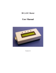
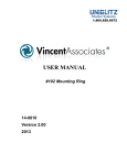
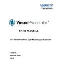
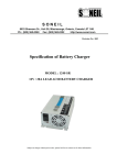
Sony Single/Dual Camera LANC Controller Board User’s Guide Thank you for purchasing our controller product. The following information will help you successfully connect this controller board to your camera(s) and get it running in your application. Overview This user’s manual covers two controller models – the ALE710 Single Camera Controller and the ALE711 Dual Camera Controller. Operation is identical except as noted. The controller board operates in two different modes – embedded mode and PC mode. In the embedded mode, the user can simply press the on-board buttons to control the camera(s) connected to the board. In the PC mode, the controller is connected to a personal computer that is used to issue the commands to control the camera(s) connected. (9) Function Buttons Pin header for External Buttons LEDs for Left Camera LEDs for Right Camera LANC Connector for Right Camera LANC Connector for Left Camera USB Type ‘B’ Connector Power Connector (5.5mm/2.5mm) Using the Controller in Embedded Applications Setting Up Using the supplied LANC cables, connect the controller board to the camera(s) that are to be controlled. Our standard cable terminates in the 2.5mm plug that is standard for LANC. If your camera uses the 10pin A/V-style connector, you will need to use an adapter to convert the 2.5mm plug to the 10-pin D connector. Check http://www.appliedlogiceng.com/index_files/Page567.htm for details. 2.5mm connector 10-pin D connector Connecting to Power The controller board comes with a standard 5.5mm outer diameter/2.5mm inner diameter barrel connector (center conductor is positive). To get you running quickly, we supply an adapter cable to allow for a 9VDC battery to be used to power the board initially. This power source runs all circuitry on the board. If desired, this battery adapter can be replaced with any DC power source between 7VDC and 15VDC. Please make sure you connect the power correctly to the board as incorrect connection may damage the board. Power On and LANC Synchronization Process* Before powering the controller board on, make sure that the cameras being controlled are connected via the supplied LANC cables. When power is applied to the controller board, the board immediately issues LANC POWER ON commands to any cameras connected to the board which will cause the cameras to power on. The controller then executes the LANC synchronization process (only with two cameras connected)*. The LANC Sync process determines how close the LANC packets are synchronized between the cameras. The controller board measures the amount of time between the start bit of Camera 1 and the start bit of Camera 2*. NOTE: You may press Switch 5 at any time to cancel the synchronization process. This is mandatory if you’re using the ALE711 with only one camera, as the board will not find the start bit of the open LANC port*. *Only applies to the ALE711 Dual Camera Controller Page 2 The sync process displays the result of the sync measurement on the controller board’s red LEDS: If both red LEDs are steady on, the cameras are synced to less than a 5 millisecond timing difference If one red LED is steady on and the other is flashing slowly (.33 sec duty cycle), the cameras are between 6-10 millisecond timing difference If one red LED is steady on and the other is flashing quickly (.10 sec duty cycle), the cameras are more than 10 millisecond timing difference. If both red LEDs are flashing quickly (.10 sec duty cycle), the synchronization routine was cancelled and the cameras are in an unknown synchronization state. The red LED that flashes represents the lagging camera, while the leading camera’s red LED is always steady on*. This information may be important for your operation, especially if you are doing 3D recording. We recommend less than 5ms synchronization for this application. If the sync measurement is unacceptable for your application, the cameras should be powered off using the POWER OFF button, and then powered back on using the POWER ON button. The sync process will then be repeated with the new results displayed on the LEDs*. *Only applies to the ALE711 Dual Camera Controller Page 3 Operating the Function Buttons Once the sync process is complete, you can then use the controller to operate the camera(s) connected to the board. Pressing any button on the controller board will simultaneously send the designated LANC command to the camera(s) connected to the controller. The buttons on the board are defined as follows: Switch 1 – Zoom In Switch 2 – Zoom Out Switch 3 – Focus Auto/Manual toggle Switch 4 – Focus Far Switch 5 – Focus Near Switch 6 – Record Start/Stop Switch 7 –Photo Capture to Memory Switch 8 -- Power Off Switch 9 – Power On The Zoom In, Zoom Out, Focus Far, and Focus Near buttons can be held down to supply continuous commands to the camera(s) for these functions. The green LEDs show an acknowledgement of a button press for the respective camera(s). *Only applies to the ALE711 Dual Camera Controller Page 4 Using the Controller Connected to a PC Installing the Software Driver You will need to download the appropriate driver from our website before you can connect your PC to the controller board. The driver can be downloaded from http://www.appliedlogiceng.com/index_files/Page1431.htm. After downloading, decompress the ZIP file and follow the instructions in the README.TXT file Once properly installed, Windows assigns a virtual COM port to this USB connection. This virtual COM port is used by the software on the PC as the communication medium. The driver supports Windows 2000, Windows XP, Windows Vista and Windows 7 (both 32 and 64 bit versions). Connecting the Controller Board to a PC The controller board has a USB connector for connection to a Personal Computer’s USB port. When using the USB port, you do not need any external power as the controller board draws its power from the USB port itself. The controller board utilizes a USB Type “B” connector. When plugged in, the board powers up and immediately sends POWER ON commands to the camera(s) attached. The controller then begins running the sync process (see above on page 3)*. When the sync process is complete, the USB port then instantiates on the PC and the virtual COM port is established on the PC. NOTE: You may press Switch 5 at any time to cancel the synchronization process. This is mandatory if you’re using the ALE711 with only one camera, as the board will not find the start bit of the open LANC port*. Sending Commands from the PC In order to send LANC commands from your PC to the camera, you must have the ALE LANC Controller software (version 2.2 and above) running on your PC. Please see the User’s Guide for our ALE704 LANC Controller Software. *Only applies to the ALE711 Dual Camera Controller Page 5 Troubleshooting After powering on, both red LEDs are off* The sync process did not complete correctly. This is usually caused by one or both cameras not connected to the LANC port, or one or both cameras did not power on when power was applied to the controller board Pressing Switch 5 or rebooting the controller board will clear the problem While power is applied to the controller board, one or both green LEDs are solid on and the board is unresponsive to button presses or commands from the PC This is usually caused by one or both of the cameras not connected to the LANC port, or one or both of the cameras are not currently power on. This issue is because the controller board is listening for the start bit of the LANC packet and the camera(s) are not actively driving the LANC bus while disconnected or powered off The controller board must be rebooted to clear this problem *Only applies to the ALE711 Dual Camera Controller Page 6